EP0967580A2 - Arbitrage centralisé de transpondeurs - Google Patents
Arbitrage centralisé de transpondeurs Download PDFInfo
- Publication number
- EP0967580A2 EP0967580A2 EP99304901A EP99304901A EP0967580A2 EP 0967580 A2 EP0967580 A2 EP 0967580A2 EP 99304901 A EP99304901 A EP 99304901A EP 99304901 A EP99304901 A EP 99304901A EP 0967580 A2 EP0967580 A2 EP 0967580A2
- Authority
- EP
- European Patent Office
- Prior art keywords
- transponder
- dispenser
- control system
- electronics
- tag
- Prior art date
- Legal status (The legal status is an assumption and is not a legal conclusion. Google has not performed a legal analysis and makes no representation as to the accuracy of the status listed.)
- Withdrawn
Links
Images


Classifications
-
- B—PERFORMING OPERATIONS; TRANSPORTING
- B67—OPENING, CLOSING OR CLEANING BOTTLES, JARS OR SIMILAR CONTAINERS; LIQUID HANDLING
- B67D—DISPENSING, DELIVERING OR TRANSFERRING LIQUIDS, NOT OTHERWISE PROVIDED FOR
- B67D7/00—Apparatus or devices for transferring liquids from bulk storage containers or reservoirs into vehicles or into portable containers, e.g. for retail sale purposes
- B67D7/06—Details or accessories
- B67D7/08—Arrangements of devices for controlling, indicating, metering or registering quantity or price of liquid transferred
- B67D7/14—Arrangements of devices for controlling, indicating, metering or registering quantity or price of liquid transferred responsive to input of recorded programmed information, e.g. on punched cards
- B67D7/145—Arrangements of devices for controlling, indicating, metering or registering quantity or price of liquid transferred responsive to input of recorded programmed information, e.g. on punched cards by wireless communication means, e.g. RF, transponders or the like
-
- B—PERFORMING OPERATIONS; TRANSPORTING
- B67—OPENING, CLOSING OR CLEANING BOTTLES, JARS OR SIMILAR CONTAINERS; LIQUID HANDLING
- B67D—DISPENSING, DELIVERING OR TRANSFERRING LIQUIDS, NOT OTHERWISE PROVIDED FOR
- B67D7/00—Apparatus or devices for transferring liquids from bulk storage containers or reservoirs into vehicles or into portable containers, e.g. for retail sale purposes
- B67D7/06—Details or accessories
- B67D7/32—Arrangements of safety or warning devices; Means for preventing unauthorised delivery of liquid
- B67D7/34—Means for preventing unauthorised delivery of liquid
- B67D7/344—Means for preventing unauthorised delivery of liquid by checking a correct coupling or coded information
- B67D7/348—Means for preventing unauthorised delivery of liquid by checking a correct coupling or coded information by interrogating an information transmitter, e.g. a transponder
-
- G—PHYSICS
- G07—CHECKING-DEVICES
- G07C—TIME OR ATTENDANCE REGISTERS; REGISTERING OR INDICATING THE WORKING OF MACHINES; GENERATING RANDOM NUMBERS; VOTING OR LOTTERY APPARATUS; ARRANGEMENTS, SYSTEMS OR APPARATUS FOR CHECKING NOT PROVIDED FOR ELSEWHERE
- G07C5/00—Registering or indicating the working of vehicles
- G07C5/008—Registering or indicating the working of vehicles communicating information to a remotely located station
-
- G—PHYSICS
- G07—CHECKING-DEVICES
- G07F—COIN-FREED OR LIKE APPARATUS
- G07F13/00—Coin-freed apparatus for controlling dispensing or fluids, semiliquids or granular material from reservoirs
- G07F13/02—Coin-freed apparatus for controlling dispensing or fluids, semiliquids or granular material from reservoirs by volume
- G07F13/025—Coin-freed apparatus for controlling dispensing or fluids, semiliquids or granular material from reservoirs by volume wherein the volume is determined during delivery
Definitions
- the present invention relates generally to communicating with transponders in a fuelling environment and, more particularly, to a dispensing system capable of arbitrating between competing tags and dispensers to ensure a dispenser communicates with the tag most proximate to that dispenser.
- POS point-of-sale
- These dispensers include various types of payment means, such as card readers, to expedite and further enhance fuelling transactions.
- a customer is not limited to the purchase of fuel at the dispenser. More recent dispensers permit the customer to purchase services, such as car washes, and goods such as fast food or convenience store products at the dispenser. Once purchased, the customer need only pick up the goods and services at the station store.
- a tag is a remote communication device capable of uni-directional or bidirectional communications to and/or from a fuel dispenser's remote communications system.
- Location arbitration is defined as the process of determining the physical closest proximity of a tag to a dispenser in applications where the proximity of the tag to the dispenser determines which dispenser and dispenser side should interact with the tag.
- tags may be within a single dispenser's communication field to provide a situation where multiple dispensers are talking with multiple tags.
- a transponder arbitration system for a dispensing environment, the system comprising; communication electronics comprising; a transmitter to transmit a polling signal; a receiver to receive response signals from responding transducers; means for generating a proximity value for the transponder based on a characteristic of the response signal; a transponder arranged to receive the polling signal and transmit a response signal including transponder identifying indicia; a control system communicatively associated with said interrogator and adapted to compare a plurality of proximity values to determine either a dispensing position most proximate to a transponder, or transponder most proximate to a dispensing position.
- a transponder arbitration method for a dispensing environment comprising: providing communication electronics associated with respective, opposing sides of a plurality of fuel dispensers, and a control system with an associated database maintained by the control system and configured to store proximity values associated with corresponding transponder identity indicia; generating the proximity values at said communication electronics based on a response signal received from transponders polled by interrogators; and comparing the proximity values associated with a certain transponder for a given response signal to determine which dispenser side is most proximate to the certain transponder.
- a retail transaction system generally designated 10, is shown and includes three subsystems: a remote communication unit 100 (hereinafter a tag); a fuel dispenser 200 and a host network 300.
- Remote communication units 100 are adapted to communicate with and through the fuel dispenser 200 in order to obtain authorisation and communicate information to and from the various susbsystems.
- the tag 100 may also communicate with other local sources 32 directly.
- the tag 100, POS device 200 and host network 300 may be adapted to encrypt and decrypt certain communications there-between.
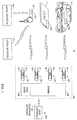
- the tag 100 is preferably integrated into a small carrying medium, such as a module mounted in or on a vehicle 12, a transaction card 14 or a key fob 16. Regardless of the medium carrying the tag 100, the tag is preferably designed to provide remote bidirectional communications with the fuel dispenser 200.
- a small carrying medium such as a module mounted in or on a vehicle 12, a transaction card 14 or a key fob 16.
- the tag is preferably designed to provide remote bidirectional communications with the fuel dispenser 200.
- Each fuel dispenser 200 in a fuel dispenser environment 20, has two fuelling positions 24.
- the dispensers are operatively associated with a central station store 26 by a conventional wire system.
- the store 26 will include a central site controller 28 to provide central control functions for the entire site including each dispenser 22.
- Each dispenser, and its respective POS (point-of-sale) electronics generally communicates either directly, or indirectly with the central site controller 28, which in turn may communicate with the host network 300 via a telephone network 30.
- the host network 300 generally provides authorisations and other data for the various transactions attempted at each fuel dispenser 200.
- the transponders 100 are also adapted to communicate with various other local sources 32 for the various informational and transaction-type functions.
- These local sources 32 may include any number of goods or service providers, such a local quick-serve restaurants.
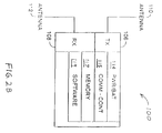
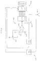
- Communications electronics 102 adapted to provide remote communications with various remote sources, includes a transmitter 106 and receiver 108 having associated antennas 110, 112. The transmitter 106 and receiver 108 operate to transmit data from and receive data into the remote communications unit 100.
- the communications electronics 102 may also include a battery power supply 114, a communication controller 116 associated with a memory 120 having the software 122 necessary to operate the communications electronics 102 and communicate with the control electronics 104.
- Serial communications between the communications electronics 102 and the control electronics 104 is provided via the input/output (I/O) ports 124, 138 associated with the respective electronics.
- the communication electronics 102 provide a clock 128 signal to the VO port 138 of the control electronics 104.
- the control electronics 104 may include a controller 130, memory 132 and software 134 to provide remote processing.
- the memory 120, 132 may include random access memory (RAM), read only memory (ROM), or a combination of both.
- the communication controller 116 and the general controller 130 may be integrated into one controller.
- the software and memory of the communication and general control modules may be merged.
- the communication electronics 104 and communications electronics 102 may be combined, and may also include encryption hardware or software.
- the communication and general control electronics, as well as any associated controllers may be integrated into a single controller system and/or integrated circuit.
- a single controller 115 is associated with memory 117 having any software 119 necessary for operation.
- the controller 115 will carry out any control functions.
- the communications electronics 102 may be the Micron MicroStampTM produced by Micron Communications.
- the communications controller 116 preferably provides a spread spectrum processor associated with an eight-bit microcontroller.
- the memory 120 includes 256 bytes of RAM.
- the receiver 108 operates in conjunction with the spread spectrum processor and is capable of receiving direct sequence spread spectrum signals having a centre frequency of 2.44175 GHZ.
- the transmitter 106 is preferably a differential phase shift key (DPSK) modulated back-scatter transmitter transmitting DPSK modulated back-scatter at 2.44175 GHZ with a 596 KHZ sub-carrier.
- DPSK differential phase shift key
- the communication electronics 102 may operate at a low-current sleep mode until an internal programmable timer causes it to wake up.
- the communication electronics 102 determines whether there is a properly modulated signal present and, if not, immediately returns to the sleep mode.
- the modulated signal which the communications electronics 102 monitors once it awakens, is provided by the fuel dispenser 200 or one of the local sources 32. If a properly modulated signal is present, the communication electronics 102 processes the received command and sends an appropriate reply. The communication electronics 102 then returns to the sleep mode.
- the communications electronics 102 causes the control electronics 104 to awaken as necessary to process data, receive information or transmit information.
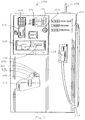
- a fuel dispenser 200 includes a control system 202 having communications electronics or interrogator 204 associated with an automatic gain control electronics 206 and one or more antennas 208.
- the control system 202 is associated with various displays 212 and input devices 214, such as keypads or touch screens.
- An audio system 215 may also be provided.
- the dispenser 200 may also be equipped with a card reader 216, cash acceptor 218 and receipt printer 220 for recording transactions.
- Each dispenser 200 is typically equipped with a fuel supply line 222, metering device 224, delivery hose 226 and a nozzle 228.
- the metering device 220 communicates data relating to the volume of fuel dispensed along line 229 to the control system 202.
- the dispenser 200 is adapted to communicate with a tag (not shown) and the central control system 28, which also communicates with the host network 300 through a standard telephone interface 30.
- the central control system 28 includes communications electronics 34 and a memory 36.
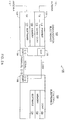
- the dispenser control system 202 and communications electronics 204 will preferably operate in association with the automatic gain control electronics 206. These systems will operate together to amplify a signal received from a tag to a normalised level to ensure proper reception and demodulation at receiver 240, which provides a demodulated output to a microcontroller 230 of the control system 202.
- the demodulated output represented information transmitted from the transponder to the dispenser.
- the microcontroller 230 will receive the demodulated information and process the information accordingly.
- the signal received at antenna 208 is initially sent to a low-noise amplifier (LNA) 241 having feedback resulting in the normalised output, which is sent to receiver 240.
- LNA low-noise amplifier
- the normalised output is also sent to the feedback circuitry in the automatic gain control electronics 206.
- These feedback components include a diode 242, capacitor 244, amplifier 248, and a potentiometer 246.
- the potentiometer 246 is connected between power (vcc) and ground and is used to provide a reference voltage at the inverting input of the amplifier 248.
- the normalised signal from the low noise amplifier 241 is rectified through the diode 242 and charges capacitor 244 to a DC level indicative of the normalised output level of the low noise amplifier 241.
- the amplifier 248 provides an output indicative of the voltage differences received at the inverting and non-inverting inputs. This difference is indicative of the difference between the normalised output of the low noise amplifier 220 and the voltage reference set by the potentiometer 246.
- the output amplifier 248 is proportional to the difference between the reference and the normalised output of the low noise amplifier 241 and is used to control the gain of the low noise amplifier 241.
- amplifier 248 will adjust the gain of the low noise amplifier 241 so that normalised output of the low noise amplifier 240 results in a DC value at the non-inverting input equal to the reference value appearing at the inverting input of the amplifier 248.
- the output of amplifier 248 is also sent to the analog to digital converter 234, which provides a digital string indicative of the amount of gain necessary to bring the signal originally received at antenna 208 up to a normalised level at the output of the low noise amplifier 241 and received by the receiver 240.
- the microcontroller will receive the digital string and associate the string with a tag identification number (ID) in memory 210.
- ID tag identification number
- the communication electronics 204 and automatic gain control electronics 206 operate to normalise the signal for reception at the receiver 240, provide a value indicative of the amount of gain necessary to provide the normalised signal for reception and demodulate information on the received signal for the microcontrol system 202.
- the communications electronics takes the form of an interrogator having the automatic gain control electronics integrated therein. The interrogator provides an indicator of signal strength as well as the receive signal itself of the control system 202.
- tag arbitration may operate according to one of two basic processes.
- the first process creates a memory stack inside the intrinsic memory of the applicable tag.
- the tag records the short term history of any attempts by dispensers to access the tag along with the attributes that indicate the quality of the interaction. Examples of these attributes include signal strength (i.e. the inverse of the gain signal determined above), number of errors recorded per transmission, and number of attempts at communication without completion.
- the dispensers place their interaction data and attributes into any tag they read and other dispensers do the same, while preserving the data from past interactions.
- the dispensers retrieve the information stored in the tags.
- the multiple dispenser review the memory records within the tag and can determine that other dispensers have recently been writing to the tag.
- Each dispenser independently makes a determination based on the interaction attribute history as to which of the dispenser was closest to the tag and, thus, should be allowed to communicate solely with the tag in question.
- the second, and preferred, process provides similar arbitration, with the exception that arbitration data is not stored in the tag, but is stored at the central site control system memory 36 (or alternatively in the dispensers or other associated system).
- the tag ID is stored in association with the dispenser communicating with the tag and the attribute indicative of proximity.
- the central control system 28 polls the various dispensers, updates the attribute records, and determines the dispensers closest to the respective tags.
- the respective control systems may monitor movement, location and continued presence of any tag with respect to any of the dispensers communicating with the tag.
- interaction histories between the various dispensers and the given tag are stored in the tag's memory 132.
- the dispenser communicating with the tag will examine the accumulated data stored on the tag and update the data as necessary for each interaction.
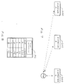
- dispensers A, B and C are either communicating or have recently communicated, with the tag shown.
- the most recently updated history of interactions are shown in Figure 8, which depicts the tag memory 132 and the history stored therein.
- the tag memory includes a series of interaction fields linking a dispenser with the relative strength of the communication associated therewith. For example, the tag memory indicates the most recent communication was made with dispenser A and the strength field has a value 200 stored in association with the communication with dispenser A.
- the strength field value i.e. the gain required to normalise the reception
- the data string from the automatic gain control electronics 206 will be lower for strong signals because the amount of gain necessary to amplify the signal received at the antenna 208 to a normalised level is low.
- the most recent communications with dispensers A, B and C i.e. the top three records
- dispenser C is the closest to the tag
- dispenser A is the furthest from the tag
- dispenser B is between A and C.
- the last three fields indicate communications with dispensers A, C and B, in that order, with resulting strength values of 175, 15 and 55, respectively.
- the values indicate that during the earlier sequence of communications with the three dispensers, dispenser C remained the closest and dispenser A was the furthest away from the tag.
- the strength values also indicate the tag was further away from dispenser C and closer to dispensers B and A than at the times of the more recent series of communications. From these values, the control system can determine that the tag is moving left to right, across drawing Figure 7 (i.e. towards dispenser C from a direction closer to dispenser A).
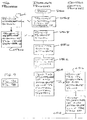
- FIGS 6A and 6B illustrate the flow of the process that begins in block D400.
- the dispenser transmits an interrogation signal (block D402), which may include a dispenser and/or position identification number, to any of the tags within communication range.
- a tag receives the interrogation signal (block T404), determines the dispenser ID (block T406) and transmits a response signal including the transponder ID and dispenser ID (block T408).
- the dispenser receives the response signal block (D410) and monitors an attribute of the signal block (D412) to determine the relative signal strength and/or proximity of the responding tag to the transponder.
- the response signal transmitted from the tag may be received at various dispensers simultaneously and each dispenser will receive the signal, monitor for signal attributes and otherwise function concurrently as discussed herein.
- the dispenser may determine the transponder ID and the dispenser ID from the received response signal (block D414) and transmit the attribute values, the associated transponder ID and the dispenser ID (block D416).
- the various tags in the communication field receive the transmission and determine whether to accept or ignore the transmission based on the transponder ID. In other words, the tags likely receive signals intended for other tags in the communication field.
- the transponder ID of the intended tag or other indicia allow the receiving tag to recognise communications intended for that particular tag and ignore communications directed to another tag.
- the receiving tag receives the transmitted attribute values and the transponder and dispenser ID's (block T418) and determines if communications were directed at the particular tag (block T420). If the communications were not meant for the tag, the transmission is ignored (block T422) and the tag waits to receive a communication directed to the tag (block T418).
- the tag stores the attribute values in association with the dispenser ID (block T421) and transmits historical information relating to the historical interaction information, including attribute values and associated dispenser ID's (block T426).
- the dispenser receives the historical information (block D428) and analyses the attribute value therein associated with each dispenser for the various communication entries (block D430).
- the dispenser determines the most proximate dispenser based on the current and historical information (block D432).
- the dispenser next determines if it is the most proximate dispenser to the tag (block D434). If it is not the most proximate dispenser, communications with that particular tag are discontinued (block D436) and the process returns to the beginning (block 438).
- the dispenser continues with communications and possibly the fuelling operation (block D440). During this period, the dispenser may continue to monitor communication attributes to derive the tag's location, determine if the tag is moving, and/or check for the continued presence of the tag.
- the dispenser updates the tags and transmits new attributes with each series of communications to the tag throughout the communication process (block D442) and, at the end of fuelling, the process will return to the beginning (block D444).
- each dispenser in the fuelling environment may be operating in the same manner. That is, various dispensers may be communicating with various tags to independently determine the dispenser closest to the tag, and each tag may communicate with various dispensers in a complimentary fashion. Thus, each dispenser independently and concurrently arbitrates among the various tags to select the tag most likely to be associated with a fuelling operation.
- a dispenser may simply overwrite the last entry. If the dispenser sees its identity in the record along with the identities of other dispensers that have entered attribute records subsequent to the dispenser's last communication, then the currently communicating dispenser may add additional records and preserve all past records, including those of other dispensers. Given that the number of records are of the finite number, it is preferred that new entries will destroy old entries in a first in first out record structure.
- the memory record 132 may be configured so that two or more competing dispensers are allowed to record a number of record attributes into the attribute history. The memory record would recycle and overwrite its oldest entries after a maximum number of entries for a particular dispenser is reached. In this way, a number of entries can be supported from each of the competing dispensers in order for each dispenser to independently calculate any average or normalised results so that a location decision can be made.
- the attribute and communication history is not stored in the tag's memory.
- the historical information is stored in a database apart from the tag and, preferably, at the central site control system 28.
- This process is shown in the flow chart of Figure 9A and 9B in association with Figures 10 and 11, which depict the dispenser and central control system communicating with a transponder ( Figure 10) and the central control system's memory record associated with the transponder ID, communicating dispenser, and the corresponding attribute value ( Figure 11).
- the attribute record shown in Figure 11 represents historical communication attributes recorded during prior communications. These records are associated with a particular transponder since they are not stored on the transponder. In other words, the historical data is simply stored in a different location than the first embodiment and associated with the transponder to which the communication relates.
- the process begins (block D500) where an interrogation signal is transmitted with a dispenser ID to the various tags in the communication field (block D502).
- the tag receives the interrogation signal block (T504) and transmits a response with the tag ID and dispenser ID (block T506).
- the dispenser receives the response signal having the tag ID and dispenser ID (block D508) and monitors attributes of the received signal (block D510).
- the dispenser determines the transponder ID and dispenser ID from the received signal (block D512) and sends these ID's along with the associated attribute values to the central control system (block D514).
- the central control system receives the transponder ID, dispenser ID and associated attribute value (block C516) and stores this information in the central control system's memory 36 (block C518).
- the central control system then analyses the attribute values of the various transponders with respect to the various dispensers (block C520).
- the central control system determines the transponder most proximate to the dispenser based on this information (block C522) and operates to have the dispensers communicate with the transponders most proximate thereto in a fashion similar to that shown in blocks C502 to C520 (block C524).
- the control system continues to monitor the location of the transponder, the movement of the transponders with respect of the dispensers and/or the presence or absence of the transponders in the various communication fields (block C526). Throughout the communication iterations, the various attribute values and historical records for each of the communications between the dispensers and transponders will be updated (block C528) until the fuelling operation is ended, wherein the process will return to the beginning (block C530). As can be appreciated, if during fuelling this continued monitoring indicates movement of the vehicle equipped with the tag in question, fuelling can be terminated to avoid fuel spillage, and alarms can sound to remind the driver that the nozzle is still in his filler pipe.
- each dispenser will have communication electronics associated with each fuelling position.
- one interrogator may be controlled in cooperation with antennas for two fuelling positions.
- the interrogator may have automatic gain control electronics 206 and be configured to transmit proximity values and transponder ID's to the central control system 28 for arbitration.
- the central control system 28 will know from which dispenser and fuelling position the information is to be received or each dispenser will transmit the information along with the transponder's ID and proximity values.
- Arbitrating at the cental control system allows overall transponder monitoring throughout the fuelling environment.
- the database kept at the central control system 28 will preferably include transponder ID's associated with fuelling positions or interrogator and proximity values received therefrom.
- the central control system will be able to effect polling at any interrogator at each dispenser by causing the interrogator's transmitter to transmit a polling signal causing the transponders receiving the polling signal to transmit a response signal including the transponder ID. Any of the interrogators receiving the response signal will generate a proximity value, preferably using the automatic gain control electronics. The proximity values and transponder ID's will be sent to the central control system for arbitration to determine the interrogator most proximate to the transponder.
- the process begins at block 600 where the central control system effects polling (block 602) of the interrogators throughout the dispenser forecourt.
- the dispenser interrogators are caused to transmit the polling signal independently of other interrogators to reduce the possibility of confusing response signals from the various transponders present in the forecourt.
- each interrogator is sequentially activated to transmit the polling signal and receive response signals. Although each of the interrogators may be activated to transmit polling signal simultaneously, activating individual interrogators or certain groups of interrogators is preferred.
- the control system will receive proximity values (block 604) and transponder ID's (block 606) from the dispensers.
- the control system will check to see if any new tags responded in the most recent polling (block 6080 by comparing the receiving transponder ID's with the ID's already stored in the database. If a new transponder s present, a timer is set (block 610) and the new transponder is assigned to the first dispenser recognising its presence. This is referred to as assigning a control token for the transponder to the corresponding dispenser fuelling position or interrogator (block 612).
- the control system may effect another polling (block 614), receive proximity values and transponder ID's (block 616), and wait for the timer to time out (block 618).
- the timer is set for a predetermined time likely to give the new transponder time to settle or stop at a particular fuelling position associated with an interrogator.
- the control system effects polling (block 602), receives proximity values (block 604) and associated ID's (block 606), and checks for the presence of any new tags (block 608).
- the control system updates the database with the new proximity values for each dispensing position or interrogator and arbitrates tag location (block 620).
- Arbitration preferably includes a comparison of proximity values for any given transponder associated with any interrogator receiving response signals from that transponder.
- the control system will determine which interrogator is most proximate to the responding transponders (block 622) and determine if any transponder assignments need to be changed. In other words, the arbitration process determines if the assignment of one transponder to a certain interrogator needs to be changed because that transponder is closer to a different interrogator than it was during a previous polling.
- control token associated with the transponder will be associated with the interrogator most proximate to the transponder during the most recent polling. If a change is necessary, the control system will assign the control token to the interrogator most proximate to the transponder (block 624). If no change is necessary, the control token assignment remains the same for the particular transponder.
- the process will next determine if the tag is at a standstill (block 626). This is accomplished by comparing proximity values for a certain transponder at an assigned interrogator over consecutive pollings. If the tag is not at a standstill, the process will again effect polling (block 602) and continue the process as described above.
- the control system will start a tag session (block 628) and begin to authorise the tag (block 630). During authorisation, the control systems will send the transponder ID along with any suitable account information to the host (block 632). The control system will request authorisation (block 634) and receive an answer accepting or declining authorisation for the given transponder (block 636). If authorisation is declined (block 638), the process ends for that particular transponder (block 640). If the transponder is authorised, the control system will preferably effect polling (block 642) and receive proximity values and transponder ID's from the various interrogators.
- the control system will determine if the transponder has been moved or removed (block 646). If the transponder is moved, the control system will effect additional polling (block 648) and check earlier arbitration results to see if the tag has moved or if communications have been re-established. Next, the control system will determine whether to pass control of the transponder or token to another interrogator (block 652).
- the control system initiates the start of a fuelling operation (block 654) and continues with the operation until fuelling has ended (block 656) wherein the process ends (block 658). If communications are not re-established or it is determined that the transponder has moved during the authorisation process, the central control system will revert back to block 602 to effect polling and rearbitrate to determine to which interrogator the transponder is most proximate and if the transponder needs to be reassigned to a new interrogator or fuelling position.
- Determining whether to keep historical data in the tags of at the central control system will depend upon the requirements of the application. Keeping the information in the respective tags allows each dispenser to independently arbitrate which tag is most proximate. These decisions are going on in parallel and do not require communications between the dispensers to facilitate arbitration. Since each dispenser is provided with identical historical data and operates on that data with identical decision processes, each dispenser will arrive at the same decision. However, certain applications may find benefit in allowing communications between the dispensers through the central control system for arbitration.
- the second embodiment may reduce communication rates, but will provide more centralised control and location monitoring throughout the fuelling environment.
- each side may have dedicated communication electronics and/or interrogators. In either situation, arbitration will typically determine not only the dispenser, but also the position a transponder is most proximate. It should be understood that all such modifications and improvements have been omitted for the sake of conciseness and readability but are properly within the scope of the following claims.
Landscapes
- Engineering & Computer Science (AREA)
- Physics & Mathematics (AREA)
- General Physics & Mathematics (AREA)
- Mechanical Engineering (AREA)
- Computer Networks & Wireless Communication (AREA)
- Mathematical Physics (AREA)
- Theoretical Computer Science (AREA)
- Loading And Unloading Of Fuel Tanks Or Ships (AREA)
- Combined Controls Of Internal Combustion Engines (AREA)
Applications Claiming Priority (2)
| Application Number | Priority Date | Filing Date | Title |
|---|---|---|---|
| US09/102,805 US6313737B1 (en) | 1998-06-23 | 1998-06-23 | Centralized transponder arbitration |
| US102805 | 1998-06-23 |
Publications (2)
| Publication Number | Publication Date |
|---|---|
| EP0967580A2 true EP0967580A2 (fr) | 1999-12-29 |
| EP0967580A3 EP0967580A3 (fr) | 2000-11-15 |
Family
ID=22291760
Family Applications (1)
| Application Number | Title | Priority Date | Filing Date |
|---|---|---|---|
| EP99304901A Withdrawn EP0967580A3 (fr) | 1998-06-23 | 1999-06-22 | Arbitrage centralisé de transpondeurs |
Country Status (4)
| Country | Link |
|---|---|
| US (1) | US6313737B1 (fr) |
| EP (1) | EP0967580A3 (fr) |
| AU (1) | AU3584799A (fr) |
| NZ (1) | NZ336422A (fr) |
Cited By (1)
| Publication number | Priority date | Publication date | Assignee | Title |
|---|---|---|---|---|
| NL1015476C2 (nl) * | 2000-06-20 | 2001-12-28 | Nedap Nv | Pompvrijgave- en betaalsysteem via mobiele telefoon. |
Families Citing this family (31)
| Publication number | Priority date | Publication date | Assignee | Title |
|---|---|---|---|---|
| US6192222B1 (en) | 1998-09-03 | 2001-02-20 | Micron Technology, Inc. | Backscatter communication systems, interrogators, methods of communicating in a backscatter system, and backscatter communication methods |
| US8538801B2 (en) * | 1999-02-19 | 2013-09-17 | Exxonmobile Research & Engineering Company | System and method for processing financial transactions |
| US7571139B1 (en) | 1999-02-19 | 2009-08-04 | Giordano Joseph A | System and method for processing financial transactions |
| US6356764B1 (en) * | 1999-03-09 | 2002-03-12 | Micron Technology, Inc. | Wireless communication systems, interrogators and methods of communicating within a wireless communication system |
| US6603391B1 (en) * | 1999-03-09 | 2003-08-05 | Micron Technology, Inc. | Phase shifters, interrogators, methods of shifting a phase angle of a signal, and methods of operating an interrogator |
| US7592898B1 (en) * | 1999-03-09 | 2009-09-22 | Keystone Technology Solutions, Llc | Wireless communication systems, interrogators and methods of communicating within a wireless communication system |
| US7076330B1 (en) | 2000-01-31 | 2006-07-11 | Gilbarco Inc. | Fraud detection through flow rate analysis |
| US6745104B1 (en) | 2000-01-31 | 2004-06-01 | Gilbarco Inc. | Fraud detection through general inference |
| US6681109B1 (en) * | 2000-05-08 | 2004-01-20 | Richard Leifer | Server call system |
| US7253717B2 (en) * | 2000-11-29 | 2007-08-07 | Mobile Technics Llc | Method and system for communicating with and tracking RFID transponders |
| US7565307B1 (en) | 2000-12-21 | 2009-07-21 | Tc License Ltd. | Automatic payment method using RF ID tags |
| US6822551B2 (en) * | 2002-11-14 | 2004-11-23 | General Hydrogen Corporation | System for communication with a vehicle in close proximity to a fixed service port |
| US7345576B2 (en) * | 2003-12-10 | 2008-03-18 | Identec Solutions Inc. | Method and apparatus for resolving RFID-based object traffic transactions to a single container in the presence of a plurality of containers |
| US8049594B1 (en) | 2004-11-30 | 2011-11-01 | Xatra Fund Mx, Llc | Enhanced RFID instrument security |
| US20060206384A1 (en) * | 2005-02-28 | 2006-09-14 | Aruze Corp. | Game medium renting machine management server and game medium renting machine management system |
| WO2007049274A2 (fr) * | 2005-10-24 | 2007-05-03 | Petratec International Ltd. | Dispositifs et procedes permettant d'autoriser des achats associes a un vehicule |
| WO2007049273A2 (fr) * | 2005-10-24 | 2007-05-03 | Petratec International Ltd. | Systeme et methode pour autoriser des achats associes a un vehicule |
| US8010067B2 (en) * | 2006-10-16 | 2011-08-30 | Goliath Solutions, Llc | Long range RFID transmitter power tracking loop |
| EP2114817B1 (fr) * | 2007-01-25 | 2013-05-01 | Petratec International Ltd. | Lecteur d'étiquettes d'identification de véhicules |
| WO2008111075A2 (fr) * | 2007-03-13 | 2008-09-18 | Petratec International Ltd. | Ensemble antenne pour station de service |
| WO2009050662A1 (fr) | 2007-10-19 | 2009-04-23 | Petratec International Ltd. | Etiquette rfid destinée à être utilisée spécialement près d'objets conducteurs |
| US20110018713A1 (en) * | 2008-02-21 | 2011-01-27 | Roseman Engineering Ltd. | Wireless Identification Device With Tamper Protection And Method Of Operating Thereof |
| US8384522B2 (en) * | 2008-09-03 | 2013-02-26 | Commscope, Inc. Of North Carolina | Radio frequency identification triangulation systems for communications patching systems and related methods of determining patch cord connectivity information |
| CA2737935C (fr) | 2009-02-11 | 2017-10-24 | William W. Segiet | Robinet distributeur de boissons controle par une technologie sans fil |
| US20100274570A1 (en) * | 2009-04-24 | 2010-10-28 | Gm Global Technology Operations, Inc. | Vehicle charging authorization |
| US20110295415A1 (en) * | 2010-06-01 | 2011-12-01 | Jack Francis Bartlett | Remote transaction system utilizing compact antenna assembly |
| EP2700057A4 (fr) | 2011-04-20 | 2014-12-31 | Gilbarco Inc | Prévention et détection de fraude pour débitmètre de distribution de carburant |
| US8433441B2 (en) | 2011-07-12 | 2013-04-30 | Gilbarco Inc. | Fuel dispenser having FM transmission capability for fueling information |
| EP2969906A4 (fr) | 2013-03-15 | 2016-11-30 | Gilbarco Inc | Détection et prévention de fraude de dispositif de mesure d'écoulement de distributeur de carburant |
| US9805538B2 (en) * | 2013-03-15 | 2017-10-31 | Zonar Systems, Inc. | Method and apparatus for fuel island authorization for trucking industry using proximity sensors |
| US10580001B2 (en) * | 2014-01-13 | 2020-03-03 | Epona Llc | Vehicle transaction data communication using communication device |
Family Cites Families (80)
| Publication number | Priority date | Publication date | Assignee | Title |
|---|---|---|---|---|
| US3536109A (en) | 1967-12-18 | 1970-10-27 | Standard Oil Co | Control mechanism for automatic dispensing of motor fuel |
| US3650303A (en) | 1970-01-02 | 1972-03-21 | Atlantic Richfield Co | Method and apparatus |
| US3642036A (en) | 1970-04-30 | 1972-02-15 | Irwin Ginsburgh | Automatic fueling system for automobiles |
| US3662924A (en) | 1971-02-26 | 1972-05-16 | Gilbert & Barker Mfg Co | Light-controlled fluid dispenser |
| US3786421A (en) | 1972-05-25 | 1974-01-15 | Atlantic Richfield Co | Automated dispensing system |
| US3814148A (en) | 1972-07-19 | 1974-06-04 | Atlantic Richfield Co | Vehicle fueling apparatus |
| US4263945A (en) | 1979-06-20 | 1981-04-28 | Ness Bradford O Van | Automatic fuel dispensing control system |
| US4532511A (en) | 1979-10-12 | 1985-07-30 | Lemelson Jerome H | Automatic vehicle identification system and method |
| US4313168A (en) | 1980-03-10 | 1982-01-26 | Exxon Research & Engineering Co. | Fluid register system |
| US4345146A (en) | 1980-03-25 | 1982-08-17 | Story James R | Apparatus and method for an electronic identification, actuation and recording system |
| GB2100705B (en) | 1981-06-23 | 1985-01-30 | Monitronix Syst | Monitored delivery systems |
| US4490798A (en) | 1981-12-16 | 1984-12-25 | Art Systems, Inc. | Fuel dispensing and vehicle maintenance system |
| FR2551741B1 (fr) | 1983-09-13 | 1986-04-11 | Aster Boutillon Volucompteurs | Dispositif de commande du mode de fonctionnement d'un distributeur d'hydrocarbure a calculateur electronique |
| US4600829A (en) | 1984-04-02 | 1986-07-15 | Walton Charles A | Electronic proximity identification and recognition system with isolated two-way coupling |
| SE442348B (sv) | 1984-07-04 | 1985-12-16 | Stiftelsen Inst Mikrovags | Forfarande och anordning for bestemning av inbordes lege mellan tva objekt |
| GB8432807D0 (en) | 1984-12-31 | 1985-02-06 | Emx International Ltd | Loop data link |
| NL8501581A (nl) | 1985-06-03 | 1987-01-02 | Nedap Nv | Werkwijze voor het selectief vullen of ledigen van opslag- of voorraadtanks. |
| US4711994A (en) | 1986-01-17 | 1987-12-08 | Princeton Synergetics, Inc. | Security system for correlating passengers and their baggage |
| NL8602148A (nl) | 1986-08-25 | 1988-03-16 | Nedap Nv | Identificatie ten behoeve van het laden en lossen van tankwagens. |
| US4804937A (en) | 1987-05-26 | 1989-02-14 | Motorola, Inc. | Vehicle monitoring arrangement and system |
| US4887578A (en) | 1987-09-25 | 1989-12-19 | Colt Industries, Inc. | On board refueling vapor recovery system |
| GB8815584D0 (en) | 1988-06-30 | 1988-08-03 | Analytical Instr Ltd | Fleet data monitoring system |
| GB2222714A (en) | 1988-09-09 | 1990-03-14 | Avery Ltd W & T | Cashless payment system |
| US4881581A (en) | 1988-09-23 | 1989-11-21 | Hollerback James A | Vehicle automatic fueling assembly |
| US4897642A (en) | 1988-10-14 | 1990-01-30 | Secura Corporation | Vehicle status monitor and management system employing satellite communication |
| US5025253A (en) | 1988-10-14 | 1991-06-18 | Secura Corporation | System and method for remotely monitoring the connect/disconnect status of a multiple part vehicle |
| US5003472A (en) | 1988-12-05 | 1991-03-26 | Wand Corporation | Apparatus for order entry in a restaurant |
| US4967366A (en) | 1989-03-06 | 1990-10-30 | Gilbarco Inc. | Integrated gasoline dispenser and POS authorization system with unattached pin pad |
| US5058044A (en) | 1989-03-30 | 1991-10-15 | Auto I.D. Inc. | Automated maintenance checking system |
| SE467972B (sv) | 1989-05-10 | 1992-10-12 | Sten Corfitsen | Anordning vid automatisk tankning av fordon |
| US5128862A (en) | 1989-06-28 | 1992-07-07 | Management Information Support, Inc. | Customer operable system for a retail store or fast-food restaurant having plural ordering stations |
| JPH03144823A (ja) | 1989-10-31 | 1991-06-20 | N T T Data Tsushin Kk | Icカードとホスト装置間の通信制御装置 |
| JP2685324B2 (ja) | 1990-02-20 | 1997-12-03 | 松下電器産業株式会社 | 電子式キャッシュレジスタ |
| US5184309A (en) | 1990-03-20 | 1993-02-02 | Saber Equipment Corp. | Fluid dispensing nozzle including in line flow meter and data processing unit |
| US5131441A (en) | 1990-03-20 | 1992-07-21 | Saber Equipment Corporation | Fluid dispensing system |
| US5363889A (en) | 1990-03-20 | 1994-11-15 | Saber Equipment Corporation | Fuel dispensing nozzle assembly |
| SE500564C2 (sv) | 1990-05-02 | 1994-07-18 | Sten Corfitsen | Förfarande och anordning vid automattankning av fordon |
| US5359522A (en) | 1990-05-09 | 1994-10-25 | Ryan Michael C | Fluid delivery control apparatus |
| US5086389A (en) | 1990-05-17 | 1992-02-04 | Hassett John J | Automatic toll processing apparatus |
| US5253162A (en) | 1990-05-17 | 1993-10-12 | At/Comm, Incorporated | Shielding field method and apparatus |
| US5072380A (en) | 1990-06-12 | 1991-12-10 | Exxon Research And Engineering Company | Automatic vehicle recognition and customer billing system |
| SE9002493L (sv) | 1990-07-24 | 1991-09-02 | Staffan Gunnarsson | Anordning vid fordon foer positionsangivning vid automatisk tankning |
| US5392049A (en) | 1990-07-24 | 1995-02-21 | Gunnarsson; Staffan | Device for positioning a first object relative to a second object |
| US5204819A (en) | 1990-08-27 | 1993-04-20 | Ryan Michael C | Fluid delivery control apparatus |
| JP2914735B2 (ja) | 1990-09-18 | 1999-07-05 | トキコ株式会社 | ロボット給油装置 |
| US5156198A (en) | 1991-02-20 | 1992-10-20 | Hall Gerald L | Pump lock fuel system |
| US5217051A (en) | 1991-11-12 | 1993-06-08 | Saber Equipment Corporation | Fuel vapor recovery system |
| US5383500A (en) | 1992-03-19 | 1995-01-24 | Shell Oil Company | Automatic refuelling system |
| DE4213880A1 (de) | 1992-04-28 | 1993-11-04 | Bosch Gmbh Robert | System zur bidirektionalen datenuebertragung zwischen mehreren feststehenden einrichtungen und einem fahrzeug |
| US5343906A (en) | 1992-05-15 | 1994-09-06 | Biodigital Technologies, Inc. | Emisson validation system |
| US5249707A (en) | 1992-06-09 | 1993-10-05 | Saber Equipment Corp. | Dispensing nozzle having a fuel flow indicator |
| US5249612A (en) | 1992-07-24 | 1993-10-05 | Bti, Inc. | Apparatus and methods for controlling fluid dispensing |
| SE501587C2 (sv) | 1992-09-04 | 1995-03-20 | Sten Corfitsen | Anordning vid automatisk tankning av fordon |
| SE500091C2 (sv) | 1992-09-04 | 1994-04-11 | Sten Corfitsen | Anordning vid automattankning av fordon |
| US5267592A (en) | 1992-12-04 | 1993-12-07 | Saber Equipment Corporation | Electrical connector for nozzle |
| CA2110025A1 (fr) | 1992-12-16 | 1994-06-17 | Gerard Joseph Hughes | Systeme automatique de reconnaissance de vehicules et de diagnostic |
| US5541835A (en) | 1992-12-29 | 1996-07-30 | Jean-Guy Bessette | Monitoring and forecasting customer traffic |
| US5351187A (en) | 1992-12-30 | 1994-09-27 | At/Comm Incorporated | Automatic debiting parking meter system |
| JPH06227597A (ja) | 1993-01-28 | 1994-08-16 | Tatsuno Co Ltd | 給油装置 |
| NL9300290A (nl) | 1993-02-16 | 1994-09-16 | Nedap Nv | Het tegelijkertijd uitlezen van meerdere detectielabels in een ondervraagveld, en het bepalen van de positie van deze labels. |
| US5499181A (en) | 1993-05-25 | 1996-03-12 | Intellectual Property Development Associates Of Connecticut, Inc. | Methods and apparatus for inputting information to a vehicle |
| US5327066A (en) | 1993-05-25 | 1994-07-05 | Intellectual Property Development Associates Of Connecticut, Inc. | Methods and apparatus for dispensing a consumable energy source to a vehicle |
| US5422624A (en) | 1993-05-25 | 1995-06-06 | Intellectual Property Development Associates Of Connecticut, Inc. | Methods and apparatus for inputting messages, including advertisements, to a vehicle |
| US5327945A (en) | 1993-08-11 | 1994-07-12 | Saber Equipment Corporation | Fuel dispensing spout |
| JPH085731A (ja) | 1993-10-04 | 1996-01-12 | Texas Instr Deutschland Gmbh | Rf−idトランスポンダの位置の決定 |
| US5485520A (en) | 1993-10-07 | 1996-01-16 | Amtech Corporation | Automatic real-time highway toll collection from moving vehicles |
| US5495250A (en) | 1993-11-01 | 1996-02-27 | Motorola, Inc. | Battery-powered RF tags and apparatus for manufacturing the same |
| IL107784A (en) | 1993-11-28 | 1998-03-10 | Orpak Ind 1983 Ltd | Fueling system |
| US5552789A (en) | 1994-02-14 | 1996-09-03 | Texas Instruments Deutschland Gmbh | Integrated vehicle communications system |
| US5471212A (en) | 1994-04-26 | 1995-11-28 | Texas Instruments Incorporated | Multi-stage transponder wake-up, method and structure |
| US5862222A (en) | 1994-05-27 | 1999-01-19 | Gunnarsson; Staffan | System at a vehicle for debiting at automatic fuelling |
| US5562133A (en) | 1994-06-24 | 1996-10-08 | Hiesky Corporation | Fuel dispensing nozzle |
| US5505234A (en) | 1994-07-15 | 1996-04-09 | Saber Equipment Corporation | Electronic trigger assembly for a fuel dispensing nozzle |
| US5602538A (en) * | 1994-07-27 | 1997-02-11 | Texas Instruments Incorporated | Apparatus and method for identifying multiple transponders |
| AU720829B2 (en) | 1995-03-13 | 2000-06-15 | Gary-Williams Retail Solutions, Inc. | Unattended automated system for selling and dispensing |
| US5605182A (en) | 1995-04-20 | 1997-02-25 | Dover Corporation | Vehicle identification system for a fuel dispenser |
| US5609190A (en) | 1995-06-05 | 1997-03-11 | Shell Oil Company | Automated refueling system |
| US5628351A (en) | 1995-06-05 | 1997-05-13 | Shell Oil Company | Method for automated refuelling |
| WO1997021626A1 (fr) | 1995-12-08 | 1997-06-19 | Gilbarco Inc. | Ravitaillement intelligent |
| SI9620132B (sl) | 1995-12-29 | 2006-04-30 | Dresser Ind | Sistem tocenja goriva in metoda identifikacije kupca z radijsko frekvenco |
-
1998
- 1998-06-23 US US09/102,805 patent/US6313737B1/en not_active Expired - Fee Related
-
1999
- 1999-06-22 EP EP99304901A patent/EP0967580A3/fr not_active Withdrawn
- 1999-06-23 NZ NZ336422A patent/NZ336422A/xx unknown
- 1999-06-23 AU AU35847/99A patent/AU3584799A/en not_active Abandoned
Cited By (2)
| Publication number | Priority date | Publication date | Assignee | Title |
|---|---|---|---|---|
| NL1015476C2 (nl) * | 2000-06-20 | 2001-12-28 | Nedap Nv | Pompvrijgave- en betaalsysteem via mobiele telefoon. |
| EP1168257A1 (fr) * | 2000-06-20 | 2002-01-02 | N.V. Nederlandsche Apparatenfabriek NEDAP | Méthode et système pour exécuter à distance une transaction entre un fournisseur de services ou de marchandises et un client |
Also Published As
| Publication number | Publication date |
|---|---|
| EP0967580A3 (fr) | 2000-11-15 |
| AU3584799A (en) | 2000-01-06 |
| US6313737B1 (en) | 2001-11-06 |
| NZ336422A (en) | 2000-12-22 |
Similar Documents
| Publication | Publication Date | Title |
|---|---|---|
| EP0967580A2 (fr) | Arbitrage centralisé de transpondeurs | |
| US6710701B2 (en) | Rfid tag location using tag or host interaction record | |
| US8924267B1 (en) | Remote payment account relational system and method for retail devices | |
| US6397126B1 (en) | Interfaced dispensing machines and remote automated payment and inventory management system | |
| AU735470B2 (en) | A forecourt ordering system for fuel and services at a filling station | |
| US20020107608A1 (en) | Fuel dispensing system for cash customers | |
| US7110954B2 (en) | Wireless purchase and on-line inventory apparatus and method for vending machines | |
| US8292168B2 (en) | System and method for authorizing purchases associated with a vehicle | |
| US6363299B1 (en) | Dispenser system for preventing unauthorized fueling | |
| US20020126632A1 (en) | Apparatus and method for using a transponder as an information buffer | |
| US5890520A (en) | Transponder distinction in a fueling environment | |
| US6089284A (en) | Preconditioning a fuel dispensing system using a transponder | |
| US6470233B1 (en) | Fuel dispensing and retail system for preventing use of stolen transponders | |
| US8113438B1 (en) | Governor arrangement for contactless point of sale terminal gateway | |
| EP0977159B1 (fr) | Terminal électronique | |
| US20030030539A1 (en) | Vending audit system | |
| US20020128957A1 (en) | Dispenser inventory monitoring system and method | |
| US20230103400A1 (en) | Intelligent electronic fueling station component provisioning | |
| US20050184155A1 (en) | Automatic payment system using RF ID tags | |
| EP1236186A2 (fr) | Systeme de paiement automatique destine a une pluralite de commercants distants | |
| US6502012B1 (en) | Newspaper rack automated inventory monitoring request apparatus and method | |
| US6735498B2 (en) | Automated newspaper rack inventory and alert management system | |
| WO1997021199A1 (fr) | Systeme de transaction pour les achats de carburant utilisant un terminal de transaction en ilot | |
| WO2011153249A1 (fr) | Système de transaction à distance utilisant un ensemble antenne compact | |
| WO1996041296A1 (fr) | Identification automatique d'objets deposes au fond d'un conteneur |
Legal Events
| Date | Code | Title | Description |
|---|---|---|---|
| PUAI | Public reference made under article 153(3) epc to a published international application that has entered the european phase |
Free format text: ORIGINAL CODE: 0009012 |
|
| AK | Designated contracting states |
Kind code of ref document: A2 Designated state(s): AT BE CH CY DE DK ES FI FR GB GR IE IT LI LU MC NL PT SE |
|
| AX | Request for extension of the european patent |
Free format text: AL;LT;LV;MK;RO;SI |
|
| RAP1 | Party data changed (applicant data changed or rights of an application transferred) |
Owner name: MARCONI COMMERCE SYSTEMS INC. |
|
| PUAL | Search report despatched |
Free format text: ORIGINAL CODE: 0009013 |
|
| AK | Designated contracting states |
Kind code of ref document: A3 Designated state(s): AT BE CH CY DE DK ES FI FR GB GR IE IT LI LU MC NL PT SE |
|
| AX | Request for extension of the european patent |
Free format text: AL;LT;LV;MK;RO;SI |
|
| RIC1 | Information provided on ipc code assigned before grant |
Free format text: 7G 07C 5/00 A, 7B 67D 5/14 B, 7B 67D 5/33 B, 7G 07F 13/02 B |
|
| AKX | Designation fees paid | ||
| REG | Reference to a national code |
Ref country code: DE Ref legal event code: 8566 |
|
| STAA | Information on the status of an ep patent application or granted ep patent |
Free format text: STATUS: THE APPLICATION IS DEEMED TO BE WITHDRAWN |
|
| 18D | Application deemed to be withdrawn |
Effective date: 20010516 |