EP0967698B1 - Wellenlängenstabilisierte Laseranordnung - Google Patents
Wellenlängenstabilisierte Laseranordnung Download PDFInfo
- Publication number
- EP0967698B1 EP0967698B1 EP99111319A EP99111319A EP0967698B1 EP 0967698 B1 EP0967698 B1 EP 0967698B1 EP 99111319 A EP99111319 A EP 99111319A EP 99111319 A EP99111319 A EP 99111319A EP 0967698 B1 EP0967698 B1 EP 0967698B1
- Authority
- EP
- European Patent Office
- Prior art keywords
- wavelength
- filter
- arrangement according
- polarizer
- optical
- Prior art date
- Legal status (The legal status is an assumption and is not a legal conclusion. Google has not performed a legal analysis and makes no representation as to the accuracy of the status listed.)
- Expired - Lifetime
Links
Images



Classifications
-
- H—ELECTRICITY
- H04—ELECTRIC COMMUNICATION TECHNIQUE
- H04B—TRANSMISSION
- H04B10/00—Transmission systems employing electromagnetic waves other than radio-waves, e.g. infrared, visible or ultraviolet light, or employing corpuscular radiation, e.g. quantum communication
- H04B10/50—Transmitters
- H04B10/501—Structural aspects
- H04B10/503—Laser transmitters
-
- H—ELECTRICITY
- H01—ELECTRIC ELEMENTS
- H01S—DEVICES USING THE PROCESS OF LIGHT AMPLIFICATION BY STIMULATED EMISSION OF RADIATION [LASER] TO AMPLIFY OR GENERATE LIGHT; DEVICES USING STIMULATED EMISSION OF ELECTROMAGNETIC RADIATION IN WAVE RANGES OTHER THAN OPTICAL
- H01S5/00—Semiconductor lasers
- H01S5/06—Arrangements for controlling the laser output parameters, e.g. by operating on the active medium
- H01S5/068—Stabilisation of laser output parameters
- H01S5/0683—Stabilisation of laser output parameters by monitoring the optical output parameters
- H01S5/0687—Stabilising the frequency of the laser
-
- H—ELECTRICITY
- H04—ELECTRIC COMMUNICATION TECHNIQUE
- H04B—TRANSMISSION
- H04B10/00—Transmission systems employing electromagnetic waves other than radio-waves, e.g. infrared, visible or ultraviolet light, or employing corpuscular radiation, e.g. quantum communication
- H04B10/50—Transmitters
- H04B10/572—Wavelength control
-
- H—ELECTRICITY
- H01—ELECTRIC ELEMENTS
- H01S—DEVICES USING THE PROCESS OF LIGHT AMPLIFICATION BY STIMULATED EMISSION OF RADIATION [LASER] TO AMPLIFY OR GENERATE LIGHT; DEVICES USING STIMULATED EMISSION OF ELECTROMAGNETIC RADIATION IN WAVE RANGES OTHER THAN OPTICAL
- H01S5/00—Semiconductor lasers
- H01S5/005—Optical components external to the laser cavity, specially adapted therefor, e.g. for homogenisation or merging of the beams or for manipulating laser pulses, e.g. pulse shaping
- H01S5/0064—Anti-reflection components, e.g. optical isolators
-
- H—ELECTRICITY
- H01—ELECTRIC ELEMENTS
- H01S—DEVICES USING THE PROCESS OF LIGHT AMPLIFICATION BY STIMULATED EMISSION OF RADIATION [LASER] TO AMPLIFY OR GENERATE LIGHT; DEVICES USING STIMULATED EMISSION OF ELECTROMAGNETIC RADIATION IN WAVE RANGES OTHER THAN OPTICAL
- H01S5/00—Semiconductor lasers
- H01S5/02—Structural details or components not essential to laser action
- H01S5/022—Mountings; Housings
- H01S5/023—Mount members, e.g. sub-mount members
- H01S5/02325—Mechanically integrated components on mount members or optical micro-benches
Definitions
- the invention relates to a wavelength-stabilized laser arrangement according to claim 1.
- optical one Isolator has the function of causing undesirable effects to suppress reflected laser light on the semiconductor laser.
- a wavelength-stabilized laser arrangement is in the unpublished German patent application DE 197 12 845.9.
- the laser beam is used to stabilize the wavelength two partial beams decoupled and from each Detectors detected.
- Beam splitter or mirror used to decouple the partial beams Beam splitter or mirror used.
- At least one the partial beams pass through an optical filter with a wavelength-dependent transmission, so that the corresponding detected signal is wavelength-dependent.
- the signal from the other detector becomes the current one Wavelength of the semiconductor laser determined and a Deviation from a predetermined setpoint is determined.
- the setting the laser wavelength to the target wavelength then via a temperature control of the semiconductor laser.
- the invention has for its object a simple and inexpensive construction of one for high transmission capacities and in particular a laser arrangement suitable for wavelength division multiplexing to create with a semiconductor laser.
- the laser arrangement according to the invention has both wavelength stabilization as well as an optical isolator and is therefore particularly high for transmission Data rates suitable for WDM operation.
- at least one of those for wavelength stabilization required partial beams via a polarizer of the optical Isolators decoupled.
- the polarizer thus fulfills two functions simultaneously, namely that of a polarizer in the optical isolator and that of a beam splitter in the wavelength stabilization circuit. This will make it a beam splitter saved as an additional component and it becomes a simple and compact overall structure achieved.
- the second polarizer is preferably (at least) as Beam splitter used and for coupling out the second partial beam used.
- the optical isolator has reflections from the filter and from the suppresses the second detector and thus prevents this affect the semiconductor laser.
- the first polarizer is expediently (also) used used as a beam splitter for coupling out the first partial beam. In this way the degree of integration and the Compactness of the arrangement according to the invention by saving another beam splitter.
- a preferred embodiment of the invention is characterized in that the filter is an edge filter or a bandpass filter is. If a bandpass filter is used, this will turn on operated one of the bandpass filter edges.
- Another preferred embodiment of the invention features differs in that another filter for filtering of the first partial beam led to the first detector becomes. It is advantageous that both filters are linear polarized light can be operated. This reduces the requirements to be placed on the filters and enables the use of inexpensive filters.
- Beam path of the first partial beam between the first polarizer and the further filter a ⁇ / 2 plate with a arrange appropriate orientation of its optical axis.
- the ⁇ / 2 plate serves to suppress the other Reflections appearing in the filter (so-called "quasi-isolator").
- the further filter preferably has a filter curve which is shifted with respect to the filter curve of the filter and runs counter to the target Wel target wavelength ⁇ 0 .
- a suitable evaluation of the detector signals can achieve a wavelength sensitivity that is twice as high with the same filter steepness as when using only one filter.
- the filter curve of the filter and the filter curve of the further filter have an intersection point at the desired wavelength ⁇ 0 .
- the wavelength of the semiconductor laser can be adjusted to the target wavelength ⁇ 0 by means of a zero point control.
- Another preferred embodiment of the invention is characterized in that the filter and / or the further filter are arranged pivotably.
- the pivotable arrangement of a filter makes it possible to adjust and adjust the center wavelength ⁇ M of the filter by tilting the filter relative to the axis of the incident partial beam. This means that the same filter can cover a whole range of different target wavelengths, which means that changing operating conditions can be mastered without the need to replace the filter.
- there is a simple adjustment possibility which makes it possible to reduce the tolerance requirements to be placed on the filter with regard to compliance with the center wavelength ⁇ M.
- the second polarizer can also be used instead of the filter and / or the first polarizer can be arranged pivotably, which gives the same effect.
- a particularly compact arrangement is achieved if the second polarizer and the filter in a more stable position to each other Relationship arranged in a common, pivotable unit are.
- the device for rotating the plane of polarization is preferred trained as a Faraday turner.
- a Faraday turner features a preferred embodiment of the invention in that the Faraday rotator itself is permanently magnetized is.
- Such Faraday rotators do not need an external one Premanentmagnete be equipped, which the lateral Decoupling of the partial beam or beams to be coupled out obstruct or complicate about the polarizer (s) can.
- the invention is Wavelength-stabilized laser arrangement in particular for the construction of high-rate laser modules of small sizes suitable.
- a laser module includes in addition to the wavelength-stabilized laser arrangement a hermetic dense module housing that the semiconductor laser, the optical Isolator and at least the optical detectors and the optical Filters the control device.
- Such one Laser module has a compact and inexpensive construction the advantage of an internal wavelength reference. It is also advantageous that the requirements of such a module to the filter are further reduced because the filter is not exposed to any moisture and also a constant Operating temperature of the filter by coupling to a the cooling device cooling the semiconductor laser in simple Way can be brought about.
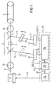
- the laser light beam 2 is made up of an optic that consists of a or can consist of several lenses, collimated or on one Entry surface of a glass fiber 4 focused.
- the optics as shown here for example consist of two lenses (or lens groups) 3a, 3b, wherein the first lens 3a is an approximately collimated laser light beam generated, which is focused by the second lens 3b becomes.
- Isolator 5 which consists of a first polarizer 6, a Faraday rotator 7 and a second polarizer 8 built is.
- an optical isolator is known in the art and serves to avoid unwanted repercussions from reflected Suppress laser light on the semiconductor laser 1.
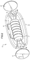
- the basic structure and the mode of operation of an optical Isolators 5 ' are shown in more detail in Fig. 2.
- the optical one Insulator 5 ' has a first polarizer 6', a Faraday rotator 7 'and a second polarizer 8'.
- the first Polarizer 6 ' generates a linearly polarized laser light beam 2 ', whose direction of polarization through the plane of polarization of the first polarizer 6 'and determined by the Vector 6a 'of the electric field strength E shown in FIG. 2 is specified.
- ⁇ 45 °
- the second polarizer 8 ' is set so that its The plane of polarization coincides with the vector 6b '. The laser light beam 2 'can thus unhindered the second polarizer 8' happen.
- the normals of the polarizers 6, 8 tilted relative to the beam axis of the laser light beam 2.
- the polarizers 6, 8 are thus used as beam splitters.
- a suitable decoupling ratio for the intensities of the first and second partial beams 10, 11, can by a corresponding Coating or anti-reflective coating of the polarizers 6, 8 can be set.
- the first partial beam 10 falls directly on a first detector 12 and is converted by the latter into a first electrical detector signal I 1 .
- the first detector signal I 1 corresponds to the intensity of the first partial beam 10 and is therefore proportional to the intensity of the laser light bundle 2.
- the second partial beam 11 runs through an optical filter 14.
- the optical filter 14 can be an edge filter (High-pass or low-pass filter) or by one on one of its Act band-pass filter operated filter edges.
- constructive can filter 14, for example, as a dielectric filter or be designed as an etalon.
- the filtered second partial beam 11 ′ that has passed through the filter 14 strikes a second detector 13.
- the second detector 13 generates a second electrical detector signal I 2 ( ⁇ ).
- the second electrical detector signal I 2 ( ⁇ ) is on the one hand proportional to the intensity of the laser light bundle 2 and on the other hand it is dependent on the laser light wavelength ⁇ due to the filter characteristic of the filter 14.
- the first and second partial beams 10, 11 'each with respect to the detector normal tilted are the first and second partial beams 10, 11 'each with respect to the detector normal tilted.
- the first detector 12 a tilt useful because its reflex is not due to the optical isolator 5 is eliminated.
- control electronics 15 which comprise a signal processing device 15a, a comparison device 15b and a control device 15c.
- the signal processing device 15a determines from the two detector signals I 1 and I 2 ( ⁇ ) an actual value signal IST ( ⁇ ) which is representative of the current laser light wavelength ⁇ and is independent of the intensity of the laser light beam 2, ie of the power of the semiconductor laser 1 ,
- a comparison device 15b connected downstream of the signal processing device 15a compares ACTUAL ( ⁇ ) with a desired value signal TARGET which specifies a desired desired wavelength ⁇ 0 .
- the comparison device 15b provides a signal ⁇ which is representative of the deviation between ACTUAL ( ⁇ ) and TARGET.
- the target wavelength ⁇ 0 can be predefined from outside.
- the deviation signal ⁇ is supplied to the control device 15c.
- the control device 15c then generates a Control signal C, the cooling element 16, for example a Peltier element that is fed.
- the cooling element 16 is in good thermal contact with the semiconductor laser 1.
- the regulation of the laser light wavelength ⁇ takes place via the Temperature dependence of the laser light emission in relation to ⁇ .
- the comparison device 15b and the control device 15c can for example in the form of a PI or a PID controller or can also be implemented as a digital controller.
- the wavelength-dependent transmission is one optical high-pass (filter curve 20) and an optical low-pass filter (Filter curve 21) shown, for example can be used as a filter 14.
- filter curve 20 an optical high-pass filter
- Finter curve 21 an optical low-pass filter
- the filter edges should be possible be steep. However, it should be borne in mind that a high Edge steepness reduced the capture area 22 of the scheme.
- the center wavelengths of the filters shown in Fig. 3a are identical.
- a filter is preferably used which can be operated in the vicinity of its center wavelength ⁇ M with respect to the desired wavelength ⁇ 0 (ie ⁇ M ⁇ ⁇ 0 ), since in this way an operating point with maximum steepness of the filter curve 20; 21 and a symmetrical capture area 22 can be obtained.
- the first detector signal I 1 is also wavelength-dependent, ie I 1 ( ⁇ ).
- the two filters 14, 17 preferably have opposite (complementary) filter curves with respect to the target wavelength ⁇ 0 .
- 3b shows suitable filter curves for the filter 14 and the filter 17.
- one of the filters 14; 17 a filter curve 23 and the other filter 17; 14 have a filter curve 24.
- Both bandpass filters are preferably operated in the region of their central wavelengths ⁇ M , which - as shown here - should expediently be identical.
- edge filters filters can be selected according to the filter curves 20 '(high-pass filter) and 21' (low-pass filter) which are shown in dash-dot lines and which correspond to the filter curves 20, 21 shown in FIG. 3a.
- the combination of an edge filter with a bandpass filter is also possible.
- the filter 14 and the optional filter 17 are preferably arranged pivotably. This enables a targeted adjustment of the center wavelength ⁇ M by tilting the respective filter 14, 17 with respect to the beam axis of the first or second partial beam 10, 11.
- the arrangement according to the invention can be used for a wide range of target wavelengths ⁇ 0 without changing the filter
- the tolerance requirements for the filters 14, 17 with regard to compliance with a center wavelength ⁇ M can be kept within a reasonable range, and a comparison of the center wavelength ⁇ M with the target wavelength ⁇ 0 and, if two filters 14, 17 are used, a comparison of the Center wavelengths of the two filters 14, 17 are carried out with each other.
- optical isolator 5 differs from that shown in FIG. 2 optical isolator 5 'in that for the Faraday twister 7 preferably a permanently magnetized material is used , whereby an external magnetic field B generating an outer Magnet (such as the solenoid 9 ') can be omitted.
- an external magnetic field B generating an outer Magnet such as the solenoid 9 '
- the first partial beam 10 is not on the first polarizer 6 from the Laser light bundle 2 can be coupled out, but can alternatively Way out of the second partial beam 11 Passing through the filter 14 or on a reflection layer be coupled out.
- the semiconductor laser 1 around an edge emitter there is also the possibility to use a laser beam as the first partial beam 11, which emits at an edge of the semiconductor laser 1 which is opposite the edge emitting the laser light beam 2.
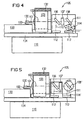
- Fig. 4 shows a first practical embodiment of the in Fig. 1 illustrated embodiment.
- a laser chip 101 is arranged on a silicon carrier 100.
- a deflection prism 130 is also mounted, by means of which a emerging at a rear edge of the laser chip 101 additional laser light bundles can be deflected and coupled out can.
- the laser light bundle 102 emitted by the laser chip 101 passes through an aspherical lens 103, for example, which in a lens mount 132 is adjustably supported, and arrives into an optical isolator 105.
- the optical isolator 105 comprises a first polarizer in the manner already described 106, a Faraday rotator 107 and a second polarizer 108.
- the polarizers 106, 108 are for coupling out of first and second partial beams 110, 111 with respect to the Beam axis of the laser light bundle 102 is arranged inclined.
- the second sub-beam 111 passes through a pivotally arranged one optical filter 114.
- first and second optical detectors are designated, the as in Fig. 1 a first and a filtered second Partial beam 110 or 111 'received.
- the silicon carrier 100 is, for example, on an AlN base plate 133 attached and is in good thermal contact with this.
- the base plate 133, the lens frame 132 and the optical isolator 105 are common on a plate 134 assembled.
- the plate 134 can be made of silicon or AlN and is on a cooling surface of a Peltier element 116 below Training of a good heat transfer is appropriate.
- the temperature of the Peltier element 116 is described in that Regulated to keep the laser wavelength ⁇ constant.
- the structure shown is also a good one Constant temperature at the lens 103, at the optical isolator 105 and achieved on the filter 114.
- the tilt angle of the filter 114 is adjusted by pivoting the filter 114 with respect to the beam axis of the second partial beam 111.
- the filter 114 is then fixed in the adjustment position found by welding, soldering or gluing.
- FIG. 5 shows a second embodiment variant of the invention.
- the same parts as in Fig. 4 are given the same reference numerals characterized.
- the embodiment shown in Fig. 5 differs from that shown in FIG. 4 Variant essentially only in that instead of the adjustment of the tilt angle of the filter 114 here is the tilt angle of the second polarizer 108 'is adjustable for adjustment purposes is.
- the second polarizer 108 ' can be rotated on one mounted, lockable axle attached while the Filter 114 'is stationary. For example, it can be immediate fixed on the entrance window of the second detector 113 his.
- FIG. 6 shows a third embodiment variant of the invention, 4 and 5 with the same parts as in FIGS are identified by the same reference numerals.
- the in Fig. 6 shown embodiment variant differs from that in 4 and 5 variants shown essentially by that here a unit 115 consisting of the second polarizer 108 "and the filter 114" is tilt-adjustable, with a fixed relative position between the second polarizer 108 "and the filter 114" is provided.
- FIG. 7a shows a partial representation of a fourth in plan view Embodiment variant of the embodiment shown in Fig. 1.
- Variants here are the arrangement of the first and second polarizer 206 and 208, Faraday rotator 207, Filters 214 and first and second detectors 212 and 213 by 90 ° tilted.
- the laser light bundle 202 and the outcoupled Partial beams 210, 211, 211 'thus run in one plane parallel to a base plate 234 that the plate 134 in the Fig. 4 to 6 corresponds to and in a manner not shown carries the laser chip.
- the filter 214 is perpendicular about an axis pivotable to the base plate 234 while the second Polarizer 208 is fixed in position.
- the arrangement corresponds to that in Fig. 4 shown first embodiment.
- the adjustment options explained with reference to FIGS. 5 and 6 Swiveling second polarizer 208 or swiveling Unit of second polarizer 208 and filter 214) realized his.
- FIG. 7b shows a side view of the fourth embodiment variant from the direction of arrow X in Fig. 7a.
- the optical isolator 205 and filter 214 are on a common, first Intermediate carrier 231 attached while the detectors 212, 213 on an adjacently arranged detector carrier 232 are upset.
- the Deflection angle expediently deviates somewhat from 90 ° chosen so that that reflected by the detectors 212, 213 Light does not hit the laser chip.
- the fourth embodiment shown in FIGS. 7a, 7b the invention is particularly advantageous when a low Overall height (standing height above the base plate 234) of the laser arrangement is required.
- the signal processing device 15a, the comparison device 15b and the control device 15c outside or inside the module housing be arranged.
Landscapes
- Physics & Mathematics (AREA)
- Electromagnetism (AREA)
- Optics & Photonics (AREA)
- Engineering & Computer Science (AREA)
- Computer Networks & Wireless Communication (AREA)
- Signal Processing (AREA)
- Condensed Matter Physics & Semiconductors (AREA)
- General Physics & Mathematics (AREA)
- Semiconductor Lasers (AREA)
Description
- Fig. 1
- eine schematische Darstellung eines Ausführungsbeispiels der Erfindung;
- Fig. 2
- eine Darstellung zur Erläuterung des Aufbaus und der Wirkungsweise eines optischen Isolators;
- Fig. 3a
- ein Diagramm, das die Wellenlängenabhängigkeit der Transmission eines optischen Hochpaßfilters und eines optischen Tiefpaßfilters zeigt;
- Fig. 3b
- ein Diagramm, das die Wellenlängenabhängigkeit der Transmission zweier optischer Bandpaßfilter zeigt;
- Fig. 3c
- ein Diagramm, das bzgl. der Fig. 3a die funktionale Abhängigkeit des Istwertes (I1-I2)/(I1+I2) von der Wellenlänge für den Fall zeigt, daß die beiden Filter ein Hochpaß- und ein Tiefpaßfilter sind, deren Transmissionskurven sich bei der Mittelwertlänge λM schneiden;
- Fig. 4
- eine schematische Seitenansicht einer ersten Variante des in Fig. 1 dargestellten Ausführungsbeispiels;
- Fig. 5
- eine schematische Seitenansicht einer zweiten Variante des in Fig. 1 dargestellten Ausführungsbeispiels;
- Fig. 6
- eine schematische Seitenansicht einer dritten Variante des in Fig. 1 dargestellten Ausführungsbeispiels;
- Fig. 7a
- eine schematische Darstellung einer vierten Ausführungsvariante des in Fig. 1 dargestellten Ausführungsbeispiels in Draufsicht; und
- Fig. 7b
- eine Seitenansicht der in Fig. 7a dargestellten vierten Ausführungsvariante aus Richtung des Pfeils X in der Fig. 7a.
- 1
- Halbleiterlaser
- 2, 2'
- Laserlichtbündel
- 3a
- erste Linse
- 3b
- zweite Linse
- 4
- Glasfaser
- 5, 5'
- optischer Isolator
- 6, 6'
- erster Polarisator
- 6a'
- Vektor der el. Feldstärke
- 6b'
- Vektor der el. Feldstärke
- 7, 7'
- Faradaydreher
- 8, 8'
- zweiter Polarisator
- 9'
- Magnetspule
- 10
- erster Teilstrahl
- 11
- zweiter Teilstrahl
- 11'
- gefilterter zweiter Teilstrahl
- 12
- erster Detektor
- 13
- zweiter Detektor
- 14
- optisches Filter
- 15
- Regelelektronik
- 15a
- Signalverarbeitungseinrichtung
- 15b
- Vergleichseinrichtung
- 15c
- Ansteuereinrichtung
- 16
- Kühlelement
- 17
- weiteres optisches Filter
- 20, 20'
- Filterkurve (Hochpaßfilter)
- 21, 21'
- Filterkurve (Tiefpaßfilter)
- 22
- Fangbereich
- 23
- Filterkurve (Bandpaßfilter)
- 24
- Filterkurve (Bandpaßfilter)
- 25
- Fangbereich
- 100
- Siliziumträger
- 101
- Laserchip
- 102
- Laserlichtbündel
- 103
- Linse
- 105
- optischer Isolator
- 106
- erster Polarisator
- 107
- Faradaydreher
- 108, 108', 108"
- zweiter Polarisator
- 110
- erster Teilstrahl
- 111
- zweiter Teilstrahl
- 111'
- gefilterter zweiter Teilstrahl
- 112
- erster Detektor
- 113
- zweiter Detektor
- 114, 114', 114"
- optisches Filter
- 115
- Einheit
- 116
- Peltier-Element
- 130
- Umlenkprisma
- 132
- Linsenfassung
- 133
- Grundplatte
- 134
- Platte
- 202
- Laserlichtbündel
- 205
- optischer Isolator
- 206
- erster Polarisator
- 207
- Faradaydreher
- 208
- zweiter Polarisator
- 210
- erster Teilstrahl
- 211
- zweiter Teilstrahl
- 211'
- gefilterter zweiter Teilstrahl
- 212
- erster Detektor
- 213
- zweiter Detektor
- 214
- optisches Filter
- 230
- Umlenkprisma
- 231
- Zwischenträger
- 232
- Detektorträger
- 234
- Basisplatte
- α
- Drehwinkel der Polarisationsebene
- B
- Magnetfeld
- C
- Steuersignal
- Δ
- Signal
- I1
- erstes Detektorsignal
- I2
- zweites Detektorsignal
- X
- Pfeil
Claims (21)
- Wellenlängenstabilisierte Laseranordnung miteinem Halbleiterlaser (1; 101) undeiner Regeleinrichtung, dieeinen ersten optischen Detektor (12; 112; 212), dem ein von dem Halbleiterlaser (1, 101) ausgekoppelter erster Teilstrahl (10) zugeführt wird,ein optisches Filter (14; 114, 114', 114"; 214)einen zweiten optischen Detektor (13; 113; 213), dem ein von dem Halbleiterlaser (1, 101) ausgekoppelter und von dem optischen Filter (14; 114, 114', 114"; 214) gefilterter zweiter Teilstrahl (11'; 111'; 211') zugeführt wird,eine Signalverarbeitungseinrichtung (15a), der ein Ausgangssignal (I1) des ersten optischen Detektors (12, 112; 212) und ein Ausgangssignal (I2) des zweiten optischen Detektors (13; 113; 213) zugeführt werden und die aus den beiden Ausgangssignalen (I1, I2) ein Istwertsignal (IST(λ)) ermittelt, das für die aktuelle Laserwel-Laserwellenlänge λ repräsentativ und unabhängig von der Laserleistung ist,eine Vergleichseinrichtung (15b), die das Istwertsignal (IST(λ)) mit einem vorgegebenen, eine Sollwellenlänge λ0 angebenden Sollwertsignal (SOLL) vergleicht undeine Ansteuereinrichtung (15c), die ein Steuersignal (C) erzeugt, das einen die zu stabilisierende Wellenlänge λ beeinflussenden Betriebsparameter des Halbleiterlasers derart einstellt, daß das Istwertsignal (IST(λ)) im wesentlichen mit dem Sollwertsignal (SOLL) übereinstimmt, umfaßt,einem im Strahlengang (2, 102, 202) des Halbleiterlasers angeordneten optischen Isolator (5; 105; 205) miteinem ersten Polarisator (6; 106; 206),einer dem ersten Polarisator (6; 106; 206) nachgeschalteten Einrichtung (7; 107; 207) zum Drehen der Licht-Polarisationsebene undeinem der Einrichtung (7; 107; 207) zum Drehen der Licht-Polarisationsebene nachgeschalteten zweiten Polarisator (8; 108; 208)wobei zumindest einer der beiden Polarisatoren (6; 106; 206; 8; 108; 208) als Strahlteiler zur Auskopplung des ersten oder zweiten Teilstrahls (10; 110; 210; 11; 111; 211) eingesetzt ist.
- Wellenlängenstabilisierte Laseranordnung nach Anspruch 1, dadurch gekennzeichnet, daß der zweite Polarisator (8; 108; 208) als Strahlteiler zur Auskopplung des zweiten Teilstrahls (11; 111; 211) eingesetzt ist.
- Wellenlängenstabilisierte Laseranordnung nach Anspruch 1 oder 2, dadurch gekennzeichnet, daß der erste Polarisator (6; 106; 206) als Strahlteiler zur Auskopplung des ersten Teilstrahls (10; 110; 210) eingesetzt ist.
- Wellenlängenstabilisierte Laseranordnung nach einem der vorhergehenden Ansprüche, dadurch gekennzeichnet, daß der oder die als Strahlteiler eingesetzten Polarisatoren (6; 106; 206; 8; 108; 208) teilverspiegelte Polarisationsfilter sind, die gegenüber einem einfallenden Laserlichtbündel (2, 102, 202) geneigt angeordnet sind.
- Wellenlängenstabilisierte Laseranordnung nach einem der vorhergehenden Ansprüche, dadurch gekennzeichnet, daß das optische Filter (14; 114, 114', 114''; 214) ein Kantenfilter oder ein Bandpaßfilter ist.
- Wellenlängenstabilisierte Laseranordnung nach einem der Ansprüche 2 bis 5, dadurch gekennzeichnet, daß ein weiteres Filter (17) zur Filterung des zum ersten Detektor (12; 112; 212) geführten ersten Teilstrahls (10; 110; 210) vorhanden ist.
- Wellenlängenstabilisierte Laseranordnung nach Anspruch 6, dadurch gekennzeichnet, daß im Strahlengang des ersten Teilstrahls (10; 110; 210) zwischen dem ersten Polarisator (6; 106; 206) und dem weiteren Filter (17) ein λ/2-Plättchen angeordnet ist.
- Wellenlängenstabilisierte Laseranordnung nach einem der Ansprüche 6 oder 7, dadurch gekennzeichnet, daß das weitere Filter (17) ein Kantenfilter oder ein Bandpaßfilter ist.
- Wellenlängenstabilisierte Laseranordnung nach einem der vorhergehenden Ansprüche, dadurch gekennzeichnet, daß das Filter (14; 114, 114', 114"; 214) und, sofern vorhanden, das weitere Filter (17) ein Interferenzfilter oder ein Etalon sind.
- Wellenlängenstabilisierte Laseranordnung nach einem der Ansprüche 6 bis 9, dadurch gekennzeichnet, daß das weitere Filter (17) eine gegenüber der Filterkurve des Filters (14; 114, 114', 114''; 214) verschobene und bezüglich der Sollwellenlänge λ0 gegenläufige Filterkurve aufweist.
- Wellenlängenstabilisierte Laseranordnung nach Anspruch 10, dadurch gekennzeichnet, daß die Filterkurve des Filters (14; 114, 114', 114"; 214) und die Filterkurve des weiteren Filters (17) bei der Sollwellenlänge λ0 einen Schnittpunkt aufweisen.
- Wellenlängenstabilisierte Laseranordnung nach einem der vorhergehenden Ansprüche, dadurch gekennzeichnet, daß das Filter (14; 114, 114"; 214) und/oder das weitere Filter (17) schwenkbar angeordnet sind.
- Wellenlängenstabilisierte Laseranordnung nach einem der vorhergehenden Ansprüche, dadurch gekennzeichnet, daß der zweite Polarisator (108', 108") und/oder der erste Polarisator (6, 106, 206) schwenkbar angeordnet sind.
- Wellenlängenstabilisierte Laseranordnung nach einem der Ansprüche 2 bis 13, dadurch gekennzeichnet, daß der zweite Polarisator (108") und das Filter (114'') in zueinander lagefester Beziehung in einer gemeinsamen, schwenkbaren Einheit (115) angeordnet sind.
- Wellenlängenstabilisierte Laseranordnung nach einem der vorhergehenden Ansprüche, dadurch gekennzeichnet,daß die Laseranordnung eine Ankoppeloptik mit einem eine Koppellinse tragenden Linsenträger zur Auskopplung eines von dem Halbleiterlaser emittierten Laserlichtbündels umfaßt, unddaß der Linsenträger mittels Beaufschlagung durch einen Laserstrahl eines externen Justagelasers gezielt und dauerhaft verformbar ist.
- Wellenlängenstabilisierte Laseranordnung nach einem der vorhergehenden Ansprüche, dadurch gekennzeichnet, daß die Einrichtung zum Drehen der Polarisationsebene ein Faradaydreher (7; 107; 207) ist.
- Wellenlängenstabilisierte Laseranordnung nach Anspruch 16, dadurch gekennzeichnet, daß der Faradaydreher (7; 107; 207) selbst permanent magnetisiert ist.
- Wellenlängenstabilisierte Laseranordnung nach einem der vorhergehenden Ansprüche, dadurch gekennzeichnet, daß der erste und/oder der zweite Detektor (12, 112, 212; 13, 113, 213) gegenüber dem ersten bzw. dem zweiten gefilterten Teilstrahl (10, 110, 210; 11', 111; 211') verkippt angeordnet sind, derart, daß ein an dem Detektor auftretender Teilstrahlreflex aus dem entsprechenden Teilstrahlengang herausgespiegelt wird.
- Wellenlängenstabilisierte Laseranordnung nach einem der vorhergehenden Ansprüche, dadurch gekennzeichnet,daß der Halbleiterlaser (1; 101) mit einer Kühleinrichtung (16; 116) in thermischen Kontakt steht, unddaß mittels der Kühleinrichtung (16; 116) als wellenlängenselektiver Betriebsparameter die Temperatur des Halbleiterlasers (1; 101) eingestellt wird.
- Wellenlängenstabilisierte Laseranordnung nach Anspruch 19, dadurch gekennzeichnet, daß der optische Isolator (5, 105, 215) und/oder das optische Filter (14; 114, 114', 114''; 214) ebenfalls mit der Kühleinrichtung (16, 116) in thermischen Kontakt steht.
- Lasermodul, dasumfaßt.eine wellenlängenstabilisierte Laseranordnung nach einem der vorhergehenden Ansprüche,ein hermetisch dichtes Modulgehäuse, das den Halbleiterlaser (1, 101), den optischen Isolator (5, 105, 205) und zumindest die optischen Detektoren (12, 112, 212; 13, 113, 213) und das optische Filter (14; 114, 114', 114"; 214) der Regeleinrichtung aufnimmt, undeine am oder außerhalb des Modulgehäuses vorgesehene Einrichtung zur Ankopplung einer optischen Faser (4)
Applications Claiming Priority (2)
| Application Number | Priority Date | Filing Date | Title |
|---|---|---|---|
| DE19827699A DE19827699A1 (de) | 1998-06-22 | 1998-06-22 | Wellenlängenstabilisierte Laseranordnung |
| DE19827699 | 1998-06-22 |
Publications (3)
| Publication Number | Publication Date |
|---|---|
| EP0967698A2 EP0967698A2 (de) | 1999-12-29 |
| EP0967698A3 EP0967698A3 (de) | 2002-07-31 |
| EP0967698B1 true EP0967698B1 (de) | 2004-10-06 |
Family
ID=7871610
Family Applications (1)
| Application Number | Title | Priority Date | Filing Date |
|---|---|---|---|
| EP99111319A Expired - Lifetime EP0967698B1 (de) | 1998-06-22 | 1999-06-08 | Wellenlängenstabilisierte Laseranordnung |
Country Status (4)
| Country | Link |
|---|---|
| US (1) | US6400739B1 (de) |
| EP (1) | EP0967698B1 (de) |
| JP (1) | JP2000031578A (de) |
| DE (2) | DE19827699A1 (de) |
Families Citing this family (30)
| Publication number | Priority date | Publication date | Assignee | Title |
|---|---|---|---|---|
| US6519068B1 (en) * | 1999-10-18 | 2003-02-11 | Agere Systems Inc. | Circuits and methods for achieving high signal-to-noise ratios and obtaining stabilized laser signals in dense wavelength division multiplexing systems |
| GB2360628A (en) * | 2000-03-25 | 2001-09-26 | Marconi Comm Ltd | A stabilised radiation source |
| CA2347551A1 (en) * | 2000-05-16 | 2001-11-16 | Furukawa Electric Co., Ltd. | Semiconductor laser apparatus |
| JP2001358362A (ja) * | 2000-06-16 | 2001-12-26 | Oki Electric Ind Co Ltd | 光モニタ,光フィルタ,および光モジュール |
| US6693928B2 (en) * | 2000-10-10 | 2004-02-17 | Spectrasensors, Inc. | Technique for filtering chirp from optical signals |
| US6671296B2 (en) | 2000-10-10 | 2003-12-30 | Spectrasensors, Inc. | Wavelength locker on optical bench and method of manufacture |
| US6587484B1 (en) * | 2000-10-10 | 2003-07-01 | Spectrasensor, Inc,. | Method and apparatus for determining transmission wavelengths for lasers in a dense wavelength division multiplexer |
| JP2002252413A (ja) * | 2001-02-26 | 2002-09-06 | Hitachi Ltd | 半導体レーザモジュール及びこれを用いた光システム |
| JP3794552B2 (ja) * | 2001-03-09 | 2006-07-05 | 古河電気工業株式会社 | 光モジュール、光送信器及び光モジュールの製造方法 |
| TW552645B (en) * | 2001-08-03 | 2003-09-11 | Semiconductor Energy Lab | Laser irradiating device, laser irradiating method and manufacturing method of semiconductor device |
| JP4087121B2 (ja) * | 2001-08-22 | 2008-05-21 | 古河電気工業株式会社 | 波長モニタおよびそれを内蔵したレーザモジュール |
| JP3993409B2 (ja) * | 2001-10-17 | 2007-10-17 | 日本オプネクスト株式会社 | 光モジュール及びその製造方法 |
| EP1329998A1 (de) | 2002-01-21 | 2003-07-23 | Agilent Technologies, Inc. (a Delaware corporation) | Arrangement für Überwachung der Emissionswellenlänge einer Laserquelle |
| US20030218283A1 (en) * | 2002-02-08 | 2003-11-27 | Yasumura Kevin Y. | Damped micromechanical device |
| EP1345298A1 (de) * | 2002-03-16 | 2003-09-17 | Agilent Technologies, Inc. (a Delaware corporation) | Wellenlängenkontrollgerät und Verfahren dafür |
| US6904067B2 (en) * | 2002-10-03 | 2005-06-07 | Intel Corporation | Back facet wavelength locker tuning and assembly method |
| EP1432088A1 (de) * | 2002-12-19 | 2004-06-23 | Agilent Technologies, Inc. - a Delaware corporation - | Wellenlängenstabilisierung für eine Halbleiterlaserdiode |
| EP1458070A1 (de) * | 2003-03-12 | 2004-09-15 | Agilent Technologies Inc. a Delaware Corporation | Optische Wellenlängen Überprüfungsanlage |
| US7253902B2 (en) * | 2004-03-31 | 2007-08-07 | Mitutoyo Corporation | Wavelength detector |
| JP5031561B2 (ja) * | 2004-06-30 | 2012-09-19 | グーグル・インコーポレーテッド | 熱制御式同調可能な外部キャビティレーザ |
| GB2418292A (en) * | 2004-09-21 | 2006-03-22 | Agilent Technologies Inc | An optical wavelength control system |
| JP2006216695A (ja) * | 2005-02-02 | 2006-08-17 | Furukawa Electric Co Ltd:The | 半導体レーザモジュール |
| JP4615428B2 (ja) * | 2005-12-02 | 2011-01-19 | 古河電気工業株式会社 | 半導体レーザモジュール |
| JP2007157937A (ja) * | 2005-12-02 | 2007-06-21 | Furukawa Electric Co Ltd:The | 半導体レーザモジュール及び半導体レーザモジュールの製造方法 |
| KR100769849B1 (ko) | 2006-11-06 | 2007-10-24 | 코닉시스템 주식회사 | 빔 프로파일 모듈 |
| JP4983312B2 (ja) * | 2007-02-28 | 2012-07-25 | 住友電気工業株式会社 | 光送信モジュール及びその出射光の波長変化又は劣化を検知する方法 |
| JP2008227170A (ja) * | 2007-03-13 | 2008-09-25 | Nec Electronics Corp | 光モジュール |
| JP6173220B2 (ja) * | 2011-02-15 | 2017-08-02 | ケーエルエー−テンカー コーポレイション | 偏光角度が調節可能な複合偏光子 |
| CA2863983C (en) | 2012-02-10 | 2022-05-10 | Nkt Photonics A/S | Laser device with frequency stabilising control module |
| JP2014225583A (ja) * | 2013-05-16 | 2014-12-04 | 富士通オプティカルコンポーネンツ株式会社 | 半導体レーザの温度制御方法、半導体レーザの温度制御装置、および半導体レーザの温度制御プログラム |
Family Cites Families (13)
| Publication number | Priority date | Publication date | Assignee | Title |
|---|---|---|---|---|
| DE2122709A1 (de) * | 1971-05-07 | 1972-11-16 | Agfa-Gevaert Ag, 5090 Leverkusen | Kinematografische oder fotografische Kamera mit Spiegelreflexsucher |
| DE2403501C3 (de) * | 1974-01-25 | 1979-02-22 | Fa. Carl Zeiss, 7920 Heidenheim | Verfahren zur Regelung der Phasenanpassung einer kohärenten Sekundärstrahlung in einem nichtlinearen Kristall |
| NL7701242A (nl) * | 1977-02-07 | 1978-08-09 | Philips Nv | Inrichting voor het verwijderen van vocht uit een ruimte. |
| US4583228A (en) * | 1983-11-21 | 1986-04-15 | At&T Bell Laboratories | Frequency stabilization of lasers |
| JPS6123379A (ja) * | 1984-07-11 | 1986-01-31 | Hitachi Ltd | 光電子装置 |
| JPH01251681A (ja) * | 1988-03-25 | 1989-10-06 | Topcon Corp | 半導体レーザーの発振周波数・発振出力安定化装置 |
| US5007065A (en) * | 1988-08-19 | 1991-04-09 | Hewlett-Packard Company | Bilithic unidirectional ring laser |
| JP2610174B2 (ja) * | 1988-09-29 | 1997-05-14 | 三菱電機株式会社 | 光アイソレータ |
| US4907237A (en) * | 1988-10-18 | 1990-03-06 | The United States Of America As Represented By The Secretary Of Commerce | Optical feedback locking of semiconductor lasers |
| JP3407893B2 (ja) * | 1991-05-27 | 2003-05-19 | パイオニア株式会社 | 半導体レーザ制御装置 |
| US5305334A (en) * | 1992-12-16 | 1994-04-19 | Litton Systems, Inc. | Pulsed solid state ring laser injection locking stabilizer |
| GB9408085D0 (en) * | 1994-04-23 | 1994-06-15 | Renishaw Plc | Frequency stabilisation of a laser diode |
| JP2871623B2 (ja) * | 1996-07-11 | 1999-03-17 | 日本電気株式会社 | 半導体レーザ装置 |
-
1998
- 1998-06-22 DE DE19827699A patent/DE19827699A1/de not_active Withdrawn
-
1999
- 1999-06-08 EP EP99111319A patent/EP0967698B1/de not_active Expired - Lifetime
- 1999-06-08 DE DE59910695T patent/DE59910695D1/de not_active Expired - Fee Related
- 1999-06-22 US US09/338,474 patent/US6400739B1/en not_active Expired - Lifetime
- 1999-06-22 JP JP11175737A patent/JP2000031578A/ja active Pending
Also Published As
| Publication number | Publication date |
|---|---|
| DE59910695D1 (de) | 2004-11-11 |
| EP0967698A2 (de) | 1999-12-29 |
| EP0967698A3 (de) | 2002-07-31 |
| US6400739B1 (en) | 2002-06-04 |
| JP2000031578A (ja) | 2000-01-28 |
| DE19827699A1 (de) | 1999-12-23 |
Similar Documents
| Publication | Publication Date | Title |
|---|---|---|
| EP0967698B1 (de) | Wellenlängenstabilisierte Laseranordnung | |
| DE68920765T2 (de) | Zusammenbau von elektrooptischen Halbleiter-Bauelementen. | |
| DE4039371C2 (de) | Einrichtung zur Stabilisierung der Wellenlänge einer Laserdiode | |
| DE69905342T2 (de) | Verfahren und vorrichtung zum überwachen und steuern der laserwellenlänge | |
| DE69711126T2 (de) | Wellenlängenmonitor und Bedienungsanordnung für WDM optische Übertragungssysteme | |
| DE69430167T2 (de) | Leitungsungebundene optische Kommunikationssysteme | |
| DE69902963T2 (de) | Abstimmbare Laserquelle mit breitbandiger und kontinuierlicher Variation der Oszillationswellenlänge | |
| DE69202993T2 (de) | Elektrisch steuerbares, wellenlängenselektives Filter. | |
| DE19621802B4 (de) | Einrichtung zum Steuern der Strahlungsintensität | |
| DE3704338C2 (de) | Einrichtung zur Erzeugung verschiedener Laserwellenlängen aus demselben Lasermedium | |
| EP3156838B1 (de) | Scannerkopf und vorrichtung mit scannerkopf | |
| DE19942905A1 (de) | Verfahren und Vorrichtung zur Stabilisierung der Winkel- und Raumlage eines Laserstrahls | |
| EP0970550B1 (de) | Lasermodul mit wellenlängenstabilisierung | |
| EP0152916B1 (de) | Laser-Doppler-Anemometer | |
| DE102006058395B4 (de) | Anordnung zur elektrischen Ansteuerung und schnellen Modulation von THz-Sendern und THz-Messsystemen | |
| DE69221457T2 (de) | Einrichtung, in der Frequenzerhöhung von elektromagnetischer Strahlung auftritt, und eine solche Einrichtung enthaltendes Gerät zum optischen Abtasten einer Informationsebene | |
| DE3750483T2 (de) | Optisches System für ein Halbleiterlaserbündel. | |
| DE69530766T2 (de) | Einrichtung zum detektieren des rotationswinkels eines beugungsgitters | |
| DE60202137T2 (de) | Stabilisiertes Fabry-Perot Interferometer und Verfahren zum Stabilisieren eines Fabry-Perot Interferometers | |
| DE10033269B4 (de) | Vorrichtung zum Einkoppeln von Licht mindestens einer Wellenlänge einer Laserlichtquelle in ein konfokales Rastermikroskop | |
| EP0831604B1 (de) | Verfahren und Vorrichtung zur Kontrolle der Ausrichtung zweier Lichtwellen bei kohärentem Überlagerungsempfang | |
| DE3939551A1 (de) | Optisches positionierungssystem fuer mindestens einen bildpunkt | |
| DE112020000803B4 (de) | Verfahren und Vorrichtung zur Charakterisierung von Laserverstärkerchips | |
| DE19633569A1 (de) | Verfahren und Vorrichtung zur Regelung der Wellenlänge monochromatischer Lichtquellen | |
| DE3421851C2 (de) | Verfahren zur Wellenlängen- und Leistungsregelung der Ausgangsstrahlung einer Halbleiterstrahlungsquelle |
Legal Events
| Date | Code | Title | Description |
|---|---|---|---|
| PUAI | Public reference made under article 153(3) epc to a published international application that has entered the european phase |
Free format text: ORIGINAL CODE: 0009012 |
|
| AK | Designated contracting states |
Kind code of ref document: A2 Designated state(s): AT BE CH CY DE DK ES FI FR GB GR IE IT LI LU MC NL PT SE |
|
| AX | Request for extension of the european patent |
Free format text: AL;LT;LV;MK;RO;SI |
|
| RAP1 | Party data changed (applicant data changed or rights of an application transferred) |
Owner name: INFINEON TECHNOLOGIES AG |
|
| PUAL | Search report despatched |
Free format text: ORIGINAL CODE: 0009013 |
|
| AK | Designated contracting states |
Kind code of ref document: A3 Designated state(s): AT BE CH CY DE DK ES FI FR GB GR IE IT LI LU MC NL PT SE |
|
| AX | Request for extension of the european patent |
Free format text: AL;LT;LV;MK;RO;SI |
|
| 17P | Request for examination filed |
Effective date: 20030107 |
|
| AKX | Designation fees paid |
Designated state(s): DE FR GB |
|
| RIC1 | Information provided on ipc code assigned before grant |
Ipc: 7H 01S 5/068 A |
|
| GRAP | Despatch of communication of intention to grant a patent |
Free format text: ORIGINAL CODE: EPIDOSNIGR1 |
|
| RIC1 | Information provided on ipc code assigned before grant |
Ipc: 7H 01S 5/068 A |
|
| RIC1 | Information provided on ipc code assigned before grant |
Ipc: 7H 01S 5/068 A |
|
| GRAS | Grant fee paid |
Free format text: ORIGINAL CODE: EPIDOSNIGR3 |
|
| GRAA | (expected) grant |
Free format text: ORIGINAL CODE: 0009210 |
|
| AK | Designated contracting states |
Kind code of ref document: B1 Designated state(s): DE FR GB |
|
| REG | Reference to a national code |
Ref country code: GB Ref legal event code: FG4D Free format text: NOT ENGLISH |
|
| REG | Reference to a national code |
Ref country code: IE Ref legal event code: FG4D Free format text: GERMAN |
|
| REF | Corresponds to: |
Ref document number: 59910695 Country of ref document: DE Date of ref document: 20041111 Kind code of ref document: P |
|
| GBT | Gb: translation of ep patent filed (gb section 77(6)(a)/1977) |
Effective date: 20050125 |
|
| REG | Reference to a national code |
Ref country code: IE Ref legal event code: FD4D |
|
| PLBE | No opposition filed within time limit |
Free format text: ORIGINAL CODE: 0009261 |
|
| STAA | Information on the status of an ep patent application or granted ep patent |
Free format text: STATUS: NO OPPOSITION FILED WITHIN TIME LIMIT |
|
| ET | Fr: translation filed | ||
| 26N | No opposition filed |
Effective date: 20050707 |
|
| REG | Reference to a national code |
Ref country code: GB Ref legal event code: 732E |
|
| PGFP | Annual fee paid to national office [announced via postgrant information from national office to epo] |
Ref country code: DE Payment date: 20070731 Year of fee payment: 9 |
|
| REG | Reference to a national code |
Ref country code: FR Ref legal event code: TP |
|
| PGFP | Annual fee paid to national office [announced via postgrant information from national office to epo] |
Ref country code: GB Payment date: 20070628 Year of fee payment: 9 |
|
| PGFP | Annual fee paid to national office [announced via postgrant information from national office to epo] |
Ref country code: FR Payment date: 20070618 Year of fee payment: 9 |
|
| GBPC | Gb: european patent ceased through non-payment of renewal fee |
Effective date: 20080608 |
|
| REG | Reference to a national code |
Ref country code: FR Ref legal event code: ST Effective date: 20090228 |
|
| PG25 | Lapsed in a contracting state [announced via postgrant information from national office to epo] |
Ref country code: DE Free format text: LAPSE BECAUSE OF NON-PAYMENT OF DUE FEES Effective date: 20090101 |
|
| PG25 | Lapsed in a contracting state [announced via postgrant information from national office to epo] |
Ref country code: GB Free format text: LAPSE BECAUSE OF NON-PAYMENT OF DUE FEES Effective date: 20080608 |
|
| PG25 | Lapsed in a contracting state [announced via postgrant information from national office to epo] |
Ref country code: FR Free format text: LAPSE BECAUSE OF NON-PAYMENT OF DUE FEES Effective date: 20080630 |