EP0967700B1 - Barre omnibus avec une borne - Google Patents
Barre omnibus avec une borne Download PDFInfo
- Publication number
- EP0967700B1 EP0967700B1 EP19990201906 EP99201906A EP0967700B1 EP 0967700 B1 EP0967700 B1 EP 0967700B1 EP 19990201906 EP19990201906 EP 19990201906 EP 99201906 A EP99201906 A EP 99201906A EP 0967700 B1 EP0967700 B1 EP 0967700B1
- Authority
- EP
- European Patent Office
- Prior art keywords
- electrical
- busbar
- terminal
- electrical busbar
- edge
- Prior art date
- Legal status (The legal status is an assumption and is not a legal conclusion. Google has not performed a legal analysis and makes no representation as to the accuracy of the status listed.)
- Expired - Lifetime
Links
- 239000004020 conductor Substances 0.000 claims description 7
- 239000007769 metal material Substances 0.000 claims description 2
- 229920003023 plastic Polymers 0.000 description 2
- 239000004033 plastic Substances 0.000 description 2
- 238000000034 method Methods 0.000 description 1
- 238000000926 separation method Methods 0.000 description 1
- 238000005476 soldering Methods 0.000 description 1
- 238000003466 welding Methods 0.000 description 1
Images

Classifications
-
- H—ELECTRICITY
- H02—GENERATION; CONVERSION OR DISTRIBUTION OF ELECTRIC POWER
- H02B—BOARDS, SUBSTATIONS OR SWITCHING ARRANGEMENTS FOR THE SUPPLY OR DISTRIBUTION OF ELECTRIC POWER
- H02B1/00—Frameworks, boards, panels, desks, casings; Details of substations or switching arrangements
- H02B1/015—Boards, panels, desks; Parts thereof or accessories therefor
- H02B1/04—Mounting thereon of switches or of other devices in general, the switch or device having, or being without, casing
- H02B1/056—Mounting on plugboards
Definitions
- the present invention relates to an electrical busbar with at least one terminal.
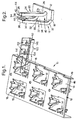
- the electrical busbar 10 in accordance with the present invention is formed by stamping in one piece from a sheet of metallic material and then folding to form the busbar with a substantially planar portion 12 and a number of terminals 14 integrally connected with the planar portion.
- the stamping and folding operations can be any suitable method and will not be described in detail.
- the planar portion 12 has a number of apertures 16.
- Each terminal 14 is formed at one edge 18 of one of the apertures 16.
- Preferably two terminals 14 are formed in each aperture 16 in edges 18 substantially perpendicular to one another.
- Each terminal 14 ( Figure 2 ) comprises a first part 20 and a second part 22.
- the first part 20 of each terminal 14 comprises a single arm 24 which is integrally connected to the respective edge 18 at one end 26 and which is free at the other end 28.
- the second part 22 of each terminal 14 comprises a pair of arms 30, each of which is integrally connected to the same edge 18 as the first part 20 at one end 32, and which are integrally joined at the other end 34 by a base portion 36, such that the second part is preferably substantially U-shaped or V-shaped.
- the ends 32 of the arms 30 of the second part 22 are positioned either side of the end 26 of the arm 24 of the first part 20.
- the arm 24 of the first part 20 lies in a first plane
- the arms 30 of the second part 22 lie in a second plane.
- the first and second planes are substantially parallel to one another, spaced apart, and substantially perpendicular to the planar portion 12.
- the space between the arms 24,30 of the first and second parts 20,22, respectively, defines a slot 38 which is open at both ends, one open end 40 being defined by the gap between the ends 32 of the arms 30 of the second part, and the other open end 42 being defined by the gap between the free end 28 of the first arm and the base portion 36 of the second arm.
- the base portion 36 of the second part 22 is preferably positioned adjacent the free end 28 of the first part 20, and the base portion and the free end preferably have raised bumps 44 which are directed towards one another. Additionally, or alternatively, substantially identical terminals may be formed at an outer edge 46 of the planar portion 12.
- each terminal 14 may receive a male terminal blade or a rigid planar electrical conductor which is inserted either through the open end 40 or through the open end 42 into the slot 38 to be frictionally gripped by, and electrically connect with, the first and second parts 20,22 of the terminal.
- a female terminal may be pushed on to the first part 20 or the second part 22, or both, of the terminal 14 to frictionally grip, and electrically connect with, the respective part.
- the raised bumps 44 on the first and second parts 20,22 assist with the frictional grip.
- the separation of the first and second parts 20,22 that is, the width of the slot 38), and/or the size of the first and second parts is determined to provide the required frictional grip.
- the electrical busbar 10 is used in an electrical centre 50 ( Figure 3 ) of a motor vehicle.
- a connector 52 is secured to the busbar 10, for example by welding or soldering, or the connector may be integrally formed with the busbar.
- the connector 52 is for providing an electrical connection between the busbar 10 and a power supply (not shown) in the motor vehicle.
- the busbar 10 is mounted on a plastics support member 54 having suitable through bores 56 for receiving the terminals 14 of the busbar. The busbar 10 and support member 54 are then slid into place in a channel 58 formed in a plastics housing 60.
- the housing 60 has apertures 62 in one surface 64, some of which align with the terminals 14 of the busbar 10, and apertures 65 in the opposed surface 66 for receiving terminals 68 secured to electrical conductors 70.
- Relays 72 or other switching devices, or electrical fuses
- the terminal blades 74 extend through the apertures 62 to either electrically connect with the terminals 14 of the busbar 10, or to electrically connected with the terminals 68 on the conductors 70, as required.
- one or more of the terminals 68 on the conductors 70 may be electrically connected to one or more of the terminals 14 of the busbar 10.
- the busbar 10 may be positioned on one side of the support member 54, as shown, or may be positioned on the opposite side of the support member.
- FIG. 1 also shows an alternative electrical busbar 100 in accordance with the present invention which can be used in conjunction with the busbar 10, or separately, to provide electrical voltage to one of the male terminal blades of electrical fuses.
- the alternative busbar 100 has a planar portion 112 and a terminal 114, substantially the same as the terminals 14 described above, formed in an outer edge 146 of the planar portion.
- the terminal 114 can mate with one of the terminals 14 of the busbar 10, or can mate with one of the terminal blades 74 of one of the relays 72, or can mate with one of the terminals 68, or can mate with any other suitable flat terminal.
- the busbar 100 also has a number of additional terminals 102 defined by bent resilient pairs of spaced arms 104 which can receive male terminal blades of electrical fuses therebetween.
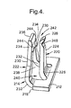
- Figure 4 shows an alternative arrangement for the terminal 214 in which, in comparison to Figure 2 , like parts have the same reference numeral prefixed by 200.
- the terminal 214 has a pair of raised bumps 244 formed on the second part 222. Each bump 244 is positioned at the other end 234 of the arms 230 where the arms join the base portion 236.
- the arm 224 of the first part 220 may have a raised bump as shown in Figure 2 , but preferably has a curved portion 248, adjacent the free end 228, which bends towards and then away from the base portion 236 of the second part 222.
- a pair of busbars in accordance with the present invention may be welded or cinched together.
- the present invention is such that an electrical busbar with integrally formed terminals can be manufactured easily and cheaply.
- the shape of the terminals 14,114,214 allows electrical connection with male blade terminals which are inserted into the terminal from either direction.
- the arrangement of the busbar is such that any changes in options for an electrical centre (within which the busbar is used) can be made without the need to change the design of the busbar.
- the busbar is therefore multi-functional in use.
Landscapes
- Engineering & Computer Science (AREA)
- Power Engineering (AREA)
- Connection Or Junction Boxes (AREA)
- Fuses (AREA)
- Coupling Device And Connection With Printed Circuit (AREA)
Claims (9)
- Barre omnibus électrique (10) formée d'une seule pièce par estampage et pliage d'une tôle de matériau métallique, la barre omnibus comprenant une portion sensiblement plane (12) et au moins une borne (14) formée de manière intégrale dans une bordure (18) de la portion plane, dans laquelle la borne ou chaque borne inclut une première partie (20) ayant un unique bras (24) intégralement connecté à une extrémité (26) à la bordure, et une seconde partie (22) ayant une paire de bras espacés (30) dont chacun est connecté intégralement à une extrémité (32) à la bordure de part et d'autre de ladite extrémité du bras unique de la première partie, les bras espacés de la seconde partie étant joints intégralement à leurs autres extrémités (34) par une portion de base (36), le bras unique de la première partie reposant dans un premier plan, les bras espacés de la seconde partie reposant dans un second plan, caractérisée en ce que le premier et le second plan sont sensiblement parallèles, sensiblement perpendiculaires à la portion plane, et espacés pour définir une fente (38) entre la première et la seconde partie, qui est ouverte aux deux extrémités (40, 42), de sorte qu'une extrémité ouverte (40) est définie par l'intervalle entre les extrémités (32) des bras espacés (30) de la seconde partie (22), et l'autre extrémité ouverte (42) est définie par l'intervalle entre l'extrémité libre (28) du bras unique (24) de la première partie (20) et la portion de base (36) des bras espacés (30) de la seconde partie (22), la fente (38) étant capable de recevoir une borne en forme de lame mâle ou un conducteur électrique plan rigide inséré à travers l'une des extrémités ouvertes (40, 42).
- Barre omnibus électrique selon la revendication 1, dans laquelle la bordure (18) de la portion plane (12) est définie par une ouverture (16) formée dans la portion plane.
- Barre omnibus électrique selon la revendication 2, dans laquelle la portion plane (12) possède un certain nombre d'ouvertures (16), chaque ouverture définissant une bordure (18) à laquelle une borne (14) est intégralement connectée.
- Barre omnibus électrique selon la revendication 3, dans laquelle chaque ouverture (16) possède une paire de bornes (14) intégralement connectées aux bordures (18) de l'ouverture, qui sont sensiblement perpendiculaires l'une à l'autre.
- Barre omnibus électrique selon la revendication 1, dans laquelle chaque bordure est définie par une bordure extérieure (46) de la portion plane (12).
- Barre omnibus électrique selon l'une quelconque des revendications 1 à 5, dans laquelle la seconde partie (22) de la borne ou de chaque borne (14) est sensiblement en forme de U ou sensiblement en forme de V.
- Barre omnibus électrique selon l'une quelconque des revendications 1 à 6, dans laquelle le bras unique (24) de la première partie (20) possède une extrémité libre (28) qui est positionnée sensiblement adjacente à la portion de base (36) de la seconde partie (22).
- Barre omnibus électrique selon la revendication 7, dans laquelle l'extrémité libre (28) du bras unique (24) et la portion de base (36) de la seconde partie (22) comporte des bosses en relief (44) formées dans celles-ci, qui sont dirigés les unes vers les autres.
- Barre omnibus électrique selon la revendication 7, dans laquelle la seconde partie (222) comprend une paire de bosses en relief (244) formées en elle-même au niveau de la jointure entre les autres extrémités (234) des bras espacés (230) et la portion de base (236), et dans laquelle la première partie (220) comprend une portion incurvée (248) adjacente à l'extrémité libre (228) de celle-ci, dirigée vers la portion de base de la seconde partie.
Applications Claiming Priority (2)
| Application Number | Priority Date | Filing Date | Title |
|---|---|---|---|
| DE1998128155 DE19828155A1 (de) | 1998-06-24 | 1998-06-24 | Elektrische Sammelschiene mit einem Anschluß |
| DE19828155 | 1998-06-24 |
Publications (2)
| Publication Number | Publication Date |
|---|---|
| EP0967700A1 EP0967700A1 (fr) | 1999-12-29 |
| EP0967700B1 true EP0967700B1 (fr) | 2009-08-12 |
Family
ID=7871881
Family Applications (1)
| Application Number | Title | Priority Date | Filing Date |
|---|---|---|---|
| EP19990201906 Expired - Lifetime EP0967700B1 (fr) | 1998-06-24 | 1999-06-15 | Barre omnibus avec une borne |
Country Status (2)
| Country | Link |
|---|---|
| EP (1) | EP0967700B1 (fr) |
| DE (2) | DE19828155A1 (fr) |
Families Citing this family (7)
| Publication number | Priority date | Publication date | Assignee | Title |
|---|---|---|---|---|
| DE10017513B4 (de) * | 2000-04-10 | 2006-10-26 | Robert Bosch Gmbh | Elektrisches Steuergerät |
| DE102008033159B3 (de) * | 2008-07-15 | 2010-04-08 | Siemens Aktiengesellschaft | Anordnung mit einer elektrischen Strom- oder Potentialschiene |
| US9028986B2 (en) | 2009-01-07 | 2015-05-12 | A123 Systems Llc | Fuse for battery cells |
| US8815429B2 (en) | 2009-01-12 | 2014-08-26 | A123 Systems Llc | Busbar supports and methods of their use for battery systems |
| WO2011069162A1 (fr) | 2009-12-04 | 2011-06-09 | A123 Systems, Inc. | Batterie comportant un système de gestion de puissance intégré et un composant de coupure de batterie extensible |
| US9478788B2 (en) | 2013-10-22 | 2016-10-25 | Ford Global Technologies, Llc | Bus bar locating feature and method |
| DE102015115464B4 (de) | 2014-09-15 | 2021-10-28 | Kromberg & Schubert Gmbh | Stromverteileranordnung |
Family Cites Families (7)
| Publication number | Priority date | Publication date | Assignee | Title |
|---|---|---|---|---|
| US4089041A (en) * | 1975-08-07 | 1978-05-09 | Amp Incorporated | Circuit programming device |
| DE3608752C1 (en) * | 1986-03-15 | 1987-05-07 | Kostal Leopold Gmbh & Co Kg | Centralised electrical system for motor vehicles |
| US4894018A (en) * | 1988-08-08 | 1990-01-16 | General Motors Corporation | Low profile electrical connector |
| US5023752A (en) * | 1989-10-31 | 1991-06-11 | General Motors Corporation | Electrical power distribution center |
| DE69103028T2 (de) * | 1990-01-16 | 1994-11-17 | Yazaki Corp | Abzweigverbindergehäuse und Sammelschiene für eine Abzweigverbindung. |
| JP2765286B2 (ja) * | 1991-07-31 | 1998-06-11 | 住友電装株式会社 | カード式ジャンクションボックス |
| DE4238867C2 (de) * | 1992-11-18 | 1995-02-02 | Fraunhofer Ges Forschung | Vorrichtung und Verfahren zum Anschließen von mehreren elektrischen Verbrauchern |
-
1998
- 1998-06-24 DE DE1998128155 patent/DE19828155A1/de not_active Withdrawn
-
1999
- 1999-06-15 DE DE69941243T patent/DE69941243D1/de not_active Expired - Lifetime
- 1999-06-15 EP EP19990201906 patent/EP0967700B1/fr not_active Expired - Lifetime
Also Published As
| Publication number | Publication date |
|---|---|
| DE19828155A1 (de) | 1999-12-30 |
| EP0967700A1 (fr) | 1999-12-29 |
| DE69941243D1 (de) | 2009-09-24 |
Similar Documents
| Publication | Publication Date | Title |
|---|---|---|
| EP1313175B1 (fr) | Connection semi-permanente entre une barre omnibus et un contact d'un connecteur électrique | |
| EP0419031B1 (fr) | Connecteur électrique à prises | |
| US5207603A (en) | Dual thickness blade type electrical terminal | |
| US4878862A (en) | Connector for mating two bus bars | |
| US4824380A (en) | Quick disconnect connector and system with integral conductor | |
| US6551129B2 (en) | Ground connector | |
| KR950034349A (ko) | 퓨즈박스 커넥터 어셈블리 | |
| EP0185471A2 (fr) | Pièce d'extrémité à déplacement d'isolant | |
| US5064380A (en) | Electrical tap and splice connector | |
| EP0967700A1 (fr) | Barre omnibus avec une borne | |
| EP0971461B1 (fr) | Barre omnibus avec terminaux femelles | |
| EP1089387A2 (fr) | Borne électrique femelle modulaire | |
| JPH11262142A (ja) | プラグイン接触子 | |
| EP0982809A2 (fr) | Borne de connexion pour conducteur électrique plat et méthode de connexion | |
| EP0128649B1 (fr) | Connecteur électrique avec cisaillement de l'isolant | |
| US5591044A (en) | Press-connecting terminal | |
| US6589084B1 (en) | Device for plug-connecting electric lines | |
| US4948380A (en) | Dual contact electrical terminal | |
| EP0867953A1 (fr) | Connecteur pour borne de batterie | |
| US4983128A (en) | Bus bar for making electrical taps | |
| US8105113B2 (en) | Fuse adapter | |
| JP2004234989A (ja) | プラグイン接触子及びバスダクト分岐構造 | |
| JP2000058176A (ja) | 方向ぎめ手段を備えた2片構成の雄型電気接触子 | |
| JP3540169B2 (ja) | 圧接端子 | |
| JPH0141180Y2 (fr) |
Legal Events
| Date | Code | Title | Description |
|---|---|---|---|
| PUAI | Public reference made under article 153(3) epc to a published international application that has entered the european phase |
Free format text: ORIGINAL CODE: 0009012 |
|
| AK | Designated contracting states |
Kind code of ref document: A1 Designated state(s): DE ES FR GB IT |
|
| AX | Request for extension of the european patent |
Free format text: AL;LT;LV;MK;RO;SI |
|
| 17P | Request for examination filed |
Effective date: 20000629 |
|
| AKX | Designation fees paid |
Free format text: DE ES FR GB IT |
|
| 17Q | First examination report despatched |
Effective date: 20080611 |
|
| GRAP | Despatch of communication of intention to grant a patent |
Free format text: ORIGINAL CODE: EPIDOSNIGR1 |
|
| GRAS | Grant fee paid |
Free format text: ORIGINAL CODE: EPIDOSNIGR3 |
|
| GRAA | (expected) grant |
Free format text: ORIGINAL CODE: 0009210 |
|
| AK | Designated contracting states |
Kind code of ref document: B1 Designated state(s): DE ES FR GB IT |
|
| REG | Reference to a national code |
Ref country code: GB Ref legal event code: FG4D |
|
| REF | Corresponds to: |
Ref document number: 69941243 Country of ref document: DE Date of ref document: 20090924 Kind code of ref document: P |
|
| PG25 | Lapsed in a contracting state [announced via postgrant information from national office to epo] |
Ref country code: ES Free format text: LAPSE BECAUSE OF FAILURE TO SUBMIT A TRANSLATION OF THE DESCRIPTION OR TO PAY THE FEE WITHIN THE PRESCRIBED TIME-LIMIT Effective date: 20091123 |
|
| PLBE | No opposition filed within time limit |
Free format text: ORIGINAL CODE: 0009261 |
|
| STAA | Information on the status of an ep patent application or granted ep patent |
Free format text: STATUS: NO OPPOSITION FILED WITHIN TIME LIMIT |
|
| 26N | No opposition filed |
Effective date: 20100517 |
|
| GBPC | Gb: european patent ceased through non-payment of renewal fee |
Effective date: 20100615 |
|
| PG25 | Lapsed in a contracting state [announced via postgrant information from national office to epo] |
Ref country code: GB Free format text: LAPSE BECAUSE OF NON-PAYMENT OF DUE FEES Effective date: 20100615 |
|
| REG | Reference to a national code |
Ref country code: FR Ref legal event code: PLFP Year of fee payment: 18 |
|
| REG | Reference to a national code |
Ref country code: FR Ref legal event code: PLFP Year of fee payment: 19 |
|
| REG | Reference to a national code |
Ref country code: FR Ref legal event code: PLFP Year of fee payment: 20 |
|
| PGFP | Annual fee paid to national office [announced via postgrant information from national office to epo] |
Ref country code: FR Payment date: 20180626 Year of fee payment: 20 |
|
| PGFP | Annual fee paid to national office [announced via postgrant information from national office to epo] |
Ref country code: IT Payment date: 20180621 Year of fee payment: 20 Ref country code: DE Payment date: 20180627 Year of fee payment: 20 |
|
| REG | Reference to a national code |
Ref country code: DE Ref legal event code: R082 Ref document number: 69941243 Country of ref document: DE Representative=s name: MANITZ FINSTERWALD PATENT- UND RECHTSANWALTSPA, DE Ref country code: DE Ref legal event code: R082 Ref document number: 69941243 Country of ref document: DE Representative=s name: MANITZ FINSTERWALD PATENTANWAELTE PARTMBB, DE Ref country code: DE Ref legal event code: R081 Ref document number: 69941243 Country of ref document: DE Owner name: APTIV TECHNOLOGIES LIMITED, BB Free format text: FORMER OWNER: DELPHI TECHNOLOGIES, INC., TROY, MICH., US |
|
| REG | Reference to a national code |
Ref country code: DE Ref legal event code: R071 Ref document number: 69941243 Country of ref document: DE |