EP0967759A2 - Réduction du traffic de diffusion dans un réseau de communication - Google Patents
Réduction du traffic de diffusion dans un réseau de communication Download PDFInfo
- Publication number
- EP0967759A2 EP0967759A2 EP99201948A EP99201948A EP0967759A2 EP 0967759 A2 EP0967759 A2 EP 0967759A2 EP 99201948 A EP99201948 A EP 99201948A EP 99201948 A EP99201948 A EP 99201948A EP 0967759 A2 EP0967759 A2 EP 0967759A2
- Authority
- EP
- European Patent Office
- Prior art keywords
- broadcast
- switching device
- forwarding
- network
- sub
- Prior art date
- Legal status (The legal status is an assumption and is not a legal conclusion. Google has not performed a legal analysis and makes no representation as to the accuracy of the status listed.)
- Granted
Links
- 230000009467 reduction Effects 0.000 title description 7
- 238000000034 method Methods 0.000 claims abstract description 7
- 238000012545 processing Methods 0.000 claims description 8
- 238000001914 filtration Methods 0.000 description 10
- 238000010586 diagram Methods 0.000 description 4
- 230000006870 function Effects 0.000 description 3
- 230000005540 biological transmission Effects 0.000 description 2
- 230000004075 alteration Effects 0.000 description 1
- 230000002238 attenuated effect Effects 0.000 description 1
- 238000006243 chemical reaction Methods 0.000 description 1
- 238000013461 design Methods 0.000 description 1
- 230000008520 organization Effects 0.000 description 1
- 238000006467 substitution reaction Methods 0.000 description 1
Images

Classifications
-
- H—ELECTRICITY
- H04—ELECTRIC COMMUNICATION TECHNIQUE
- H04L—TRANSMISSION OF DIGITAL INFORMATION, e.g. TELEGRAPHIC COMMUNICATION
- H04L12/00—Data switching networks
- H04L12/28—Data switching networks characterised by path configuration, e.g. LAN [Local Area Networks] or WAN [Wide Area Networks]
- H04L12/46—Interconnection of networks
- H04L12/4604—LAN interconnection over a backbone network, e.g. Internet, Frame Relay
- H04L12/4616—LAN interconnection over a LAN backbone
Definitions
- This invention relates generally to packet switching and in particular to a method and system of reducing broadcast packet traffic through a switching device.
- Internetworking refers to linking individual local area networks (LANs) or LAN segments together to form one integrated, seamless network.
- LANs local area networks
- the simplest internetworking device regenerates signals that have been attenuated and/or distorted, thus permitting the signal to be transmitted greater distances.
- the repeater operates at the physical layer of the Open System Interconnection (OSI) reference model.
- OSI Open System Interconnection
- the OSI reference model is a standard produced by the International Organization for Standardization (ISO) for worldwide communications that defines a framework for implementing communications protocols.
- the framework consists of seven layers.
- the various layers refer to software protocol levels, with each layer performing functions for the layers above it.
- the layers as shown in the OSI Reference Model 100 in Fig. 1 include an application layer 102, a presentation layer 104, a session layer 106, a transport layer 108, a network layer 110, a data link layer 112, and a physical layer 114.
- the application layer 102 defines program-to-program communications.
- the presentation layer 104 manages data representation conversions, i.e., converting from EBCDIC to ASCII.
- the session layer 106 is responsible for establishing and maintaining communications channels.
- the session layer 106 is sometimes combined with the transport layer 108 which is responsible for end-to-end integrity of data transmission.
- the network layer 110 defines the protocol for routing data from one node to another while the data link layer 112 is responsible for physically passing the data from one node to another. Functions such as error control, addressing, and flow control are also performed in the data link layer 112.
- the physical layer 114 manages the placement of data onto and removal of data from the network media.
- a bridging device typically is a two port device which connects two LANs together and forwards (or filters) data packets between the two LANs based on their destination address.
- the bridging device operates at the data link 112 (or media access control (MAC)) layer in the OSI reference model 100.
- MAC media access control
- a routing device is a host that is connected to more than one LAN and routes messages between them based on specific protocol rather than by packet address.
- the routing device is used to link together two or more LANs that operate different protocols.
- the routing device which routes data between two or more LANs using one of many different protocols, operates at the network layer 110.
- the routing device interconnects two or more LANs (or divides one LAN into two or more LAN segments) logically rather than physically.
- the routing device is not transparent to other nodes on the network but is itself a host, i.e., an addressable node.
- a host is generally a node on a network that can be used interactively, i.e., logged into, like a computer.
- Each host, or node has one or more associated addresses, including at least one fixed hardware address assigned by the device manufacturer.
- Most nodes also have a protocol specific address, such as an Internet protocol (IP) address, which is assigned by a network manager.
- IP Internet protocol
- the gateway is the most complex of the internetworking devices. It operates across all seven layers of the OSI reference model 100 and provides a complete hardware and software translation between the networks it connects. The gateway thus functions to connect networks of different architectures and operating under different protocols.
- a switching device is a multiport device designed to increase network performance by allowing only certain traffic on the individual LANs or LAN segments attached to its ports.
- the switching device forwards packets between LANs based upon both their source and destination addresses. Thus, traffic is routed between only those ports that require it.
- Each port on the switching device may be connected to a single computer or to a concentrator, or hub, which allows the bandwidth of the port to be shared among several users.
- VLANs virtual LANs
- the switching device may be a managed switch.
- Switches are commonly managed by simple network management protocol (SNMP) applications. These SNMP applications communicate with the managed devices using a communications protocol, such as internet protocol (IP). All managed devices, including the switch, thus have one or more IP addresses.
- All managed devices, including the switch thus have one or more IP addresses.
- Workgroups which include clients, servers, or clients and servers, appear as one or more IP sub-nets.
- a sub-net is a group of devices whose IP addresses have the same prefix.
- a device which belongs to more than one sub-net will thus have multiple IP addresses, i.e., one for each sub-net.
- An IP address includes a network address component and a host address component.
- the sub-net to which a device belongs is identified using a sub-net mask.
- the sub-net mask is the network address plus the bit or bits reserved for identifying the sub-net.
- the sub-net mask is called a mask in that by performing a bitwise AND operation on the IP address and the sub-net mask, the sub-net to which the IP address belongs is identified.
- router cost per port is significantly greater than switch cost per port.
- routing devices cause increased network latencies (the amount of time required to determine if a packet should be filtered or forwarded).
- the present invention is a method and system for processing broadcast packets in a network using a switching device which interconnects sub-portions of the network. Each network sub-portion is connected to at least one of a plurality of switch ports on the switching device.
- the switching device is operable to forward certain of the broadcast packets between the sub-portions of the network via the switch ports in accordance with a forwarding algorithm. Certain of the switch ports are identified as filtered ports. Packets received through one of the switch ports include a destination port identifier. If the destination port is not a filtered port, the present invention forwards the received packet in accordance with the switch forwarding algorithm. If the destination port is a filtered port, the present invention is operable to forward the received packet to a data processor. The data processor is operable to forward the received packet in accordance with a set of broadcast forwarding heuristics.
- An object of the present invention is to reduce broadcast packet traffic on selected ports on the switching device.
- Another object of the present invention is to implement broadcast packet routing using a set of broadcast forwarding heuristics.
- Fig. 2 illustrates an exemplary network 250 interconnected using a switching device 200 in accordance with the present invention.
- the switching device 200 includes four ports P1 232, P2 236, P3 240, and P4 244 which interconnect devices on two sub-nets, sub-net A 204 and sub-net B 202.
- Sub-net A 204 includes Host A3 222 (which is connected through port P4 244 of the switching device 200), a sub-net 226 (which interconnects two devices, Host A1 228 and Host A2 224, through port P1 232 of the switching device 200), and gateway 220 (which is connected through port P2 236 of the switching device 200).
- Sub-net B 202 includes a sub-net 208 (which interconnects two devices, Host B1 206 and Host B2 210, through port P3 240 of the switching device 200), and the gateway 220.
- the host address portion of each device in the network 250 shown in Fig. 2 is also shown.
- Host B1 206 has a host address of .2.1
- Host B2 210 has a host address of .2.2
- the gateway 220 which is a multi-homed device, has two host addresses, .2.9 and .1.9, one for each of the sub-nets, sub-net A 204 and sub-net B 202, in which it is a member.
- the gateway 220 connects the network 250 to other devices, not shown, through Internet connection 260.
- Fig. 3 depicts the switching device 200 of the present invention in more detail.
- the switching device 200 includes a modified forwarding module 310 which forwards most packets it receives through bus interface 350 from the ports P1 232, P2 236, P3 240, P4 244 in accordance with a standard forwarding algorithm.
- Broadcast packets received by the switching device 200 destined for certain ports P1 232, P2 236, P3 240, P4 244, however, in the preferred embodiment of the present invention, are transferred to data processor 320 which executes apply heuristics module 324 to generate instructions for forwarding the broadcast packets in accordance with broadcast forwarding heuristics stored in memory 330.
- the data processor 320 may be a microprocessor or a programmed digital signal processor.
- the broadcast packets which are determined to require forwarding by the apply heuristics module 324 are then transferred through port interface 350.
- the switching device (S) is connected to two networks (sub-nets A and B), plus a default gateway router (G).
- This is a common topology for a switch (a topology with a central file server, not shown, in place of Host A3 would be similar).
- the gateway router (G) is VLAN aware and multi-homed (i.e., it is part of both sub-net A and sub-net B), and thus can route between sub-nets on individual VLANs.
- the basic VLAN aware switching device (S) that is connected between sub-net A and sub-net B has no routing capabilities.
- the network topology shown in Fig. 3 provides for good traffic reduction between sub-net A and sub-net B, but unfortunately in a typical switch configuration, the gateway (G) on port P2 of the switching device (S) would be forwarded all broadcast traffic for both sub-nets A and B. This is because, although the gateway (G) is a well-known device, the gateway (G) must see a sub-set of all broadcast traffic (e.g., address resolution protocol (ARP) requests for network addresses .1.9 and .2.9, Internet control message protocol (ICMP) router solicitations, routing information protocol (RIP) packets etc.), and the switching device (S) cannot normally distinguish between useful and non-useful broadcast packets.
- ARP address resolution protocol
- ICMP Internet control message protocol
- the present invention addresses the problem by the addition of a rudimentary routing ability to the switching device 200.
- the switching device 200 acts as a "broadcast router" for gateway (G) on both sub-nets A and B. This feature is practically free since the switching device 200 must listen to the all broadcast traffic in order to provide a standard management interface.
- the broadcast router-like features added to the switching device 200 of the present invention includes a modified forwarding module 310 that allows the switching device 200 to filter out all broadcast traffic for specified ports P1 232, P2 236, P3 240, P4 244.
- the data processor 320 executing an algorithm which generates forwarding instructions in accordance with broadcast forwarding heuristics then forwards any broadcast traffic to the specified ports that devices on those ports need to see.
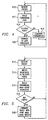
- Fig. 4 shows a flow chart illustrating operation of the modified forwarding module 310 in accordance with the present invention.
- a packet is received by the switching device 200 from one of the ports P1 232, P2 236, P3 240, P4 244. Processing then proceeds to block 412 where a forwarding code is constructed which identifies the destination port.
- a forwarding code is constructed which identifies the destination port.
- decision block 414 if the destination port is not a filtered port, processing continues at block 416 where the switching device 200 executes its standard forwarding algorithm. Whether a port is a filtered port or not is pre-determined and the information stored, for example, in a look-up table or hard-wired into the switching device 200.
- Fig. 5 depicts a flow chart illustrating operation of the apply heuristic module 324 in accordance with the present invention.
- a packet is received from the switching device 200. Operation then continues at block 512 where the broadcast forwarding heuristics from the memory 330 are matched to the filtered ports identified.
- a forwarding mask is constructed using the retrieved broadcast forwarding heuristics. Processing then continues at decision block 516 where, if no ports are specified in the resulting forwarding mask, i.e., the forwarding mask is all zero, processing continues at block 510 to retrieve the next packet. If, at decision block 516, the forwarding mask identifies ports to forward the packet to, then processing continues at block 518 where the broadcast packet, along with the associated port mask is transferred to the switching device 200 for forwarding to the appropriate port or ports.
- broadcast routing is implemented in the present invention using a collection of broadcast forwarding heuristics for each port P1 232, P2 236, P3 240, and P4 244 participating in broadcast traffic reduction.
- the broadcast routing heuristics are stored in the memory 330 which, although shown internal to the switching device 200, may be externally located.
- the broadcast routing heuristics may be either inclusive (defining what packets to forward) or exclusive (defining what packets not to forward), or a combination of both inclusive and exclusive broadcast routing heuristics.
- Inclusive rules allow for greater traffic reduction in that only specifically defined traffic is forwarded.
- exemplary inclusive heuristics for port P2 236 include:
- Exclusive rules allow for less traffic reduction in that they only specify what not to forward. However, exclusive rules allow the network administrator to be more specific in the exact type of packet traffic to filter.
- An exemplary exclusive heuristic includes:
- the type of broadcast forwarding applied depends on the specific network configuration used.
- the following example further illustrates the operation of the present invention.
- the example has been significantly simplified from an actual implementation.
- a broadcast filtering mask is constructed for the above ports where the first least significant bit (bit 0) represents port P1 232, the second bit (bit 1) represents port P2 236, and so on. Assuming the bits in the filtering mask are SET to logical '1' to indicate filtering, the filtering mask for the above switch is [1011], where port P3 240 (bit 2) is the only unfiltered port.
- the switch mechanics generate a forwarding code for each packet received.
- the forwarding code is constructed such that the first least significant bit (bit 0) represents port P1 232, the second bit (bit 1) represents port P2 236, and so on. Assume the bits are SET to logical '1' in the mask if a packet is to be forwarded to the corresponding port.
- the first example is that port P2 236 receives a broadcast packet on VLAN B.
- the packet should be forwarded to all VLAN B members, and thus a forwarding code of [0100] is constructed such that port P3 240 is the destination of the packet.
- the forwarding code is then combined with the filtering mask using a bitwise AND operation to determine if any filtering/forwarding heuristics apply.
- the result of the AND operation is NULL [0000], thus no filtering or broadcast forwarding heuristics apply.
- the packet is thus forwarded as usual.
- port P1 232 receives a broadcast IP packet destined for IP address .1.9 (e.g., an ARP request). Since port P1 232 is on VLAN A, and all VLAN A members are to receive broadcast packets, a forwarding code of [1010] is generated to indicate that ports P2 236 and P4 244 are to receive the packet. As with the previous example, the forwarding code is then combined with the filtering mask using a bitwise AND operation to determine if any filtering/forwarding heuristics apply. In this case, the result of the AND operation is [1010], indicating, that forwarding heuristics do apply.
- the packet is forwarded to the apply heuristics module 324 (which is executed by the data processor 320), which builds a new forwarding mask.
- the apply heuristics module 324 executed by the data processor 320 determines that the packet SHOULD be forwarded to port P2 236, but NOT to port P4 244.
- the apply heuristics module 324 executing on the data processor 320 then constructs a new forwarding code of [0010] to indicate that port P2 236 is the only destination port for this packet.
- the code generated by the apply heuristics module 324 [0010] is combined with the original forwarding code [1010] and the filtering mask [1011] to create the final forwarding code. This allows the inclusion of non-filtered ports. In this case, the original forwarding code [1010] does not include any non-filtered ports and thus the final forwarding code is [0010].
Landscapes
- Engineering & Computer Science (AREA)
- Computer Networks & Wireless Communication (AREA)
- Signal Processing (AREA)
- Data Exchanges In Wide-Area Networks (AREA)
Applications Claiming Priority (2)
| Application Number | Priority Date | Filing Date | Title |
|---|---|---|---|
| US9066598P | 1998-06-25 | 1998-06-25 | |
| US90665P | 1998-06-25 |
Publications (3)
| Publication Number | Publication Date |
|---|---|
| EP0967759A2 true EP0967759A2 (fr) | 1999-12-29 |
| EP0967759A3 EP0967759A3 (fr) | 2000-07-05 |
| EP0967759B1 EP0967759B1 (fr) | 2009-02-25 |
Family
ID=22223754
Family Applications (1)
| Application Number | Title | Priority Date | Filing Date |
|---|---|---|---|
| EP99201948A Expired - Lifetime EP0967759B1 (fr) | 1998-06-25 | 1999-06-17 | Réduction du traffic de diffusion dans un réseau de communication |
Country Status (4)
| Country | Link |
|---|---|
| US (1) | US6556575B1 (fr) |
| EP (1) | EP0967759B1 (fr) |
| DE (1) | DE69940451D1 (fr) |
| TW (1) | TW429712B (fr) |
Cited By (1)
| Publication number | Priority date | Publication date | Assignee | Title |
|---|---|---|---|---|
| EP1615405A2 (fr) | 2004-07-08 | 2006-01-11 | Avaya Communication Israel Ltd. | Économie d'énergie dans réseaux sans fil par filtrage sélectif de paquets de broadcast |
Families Citing this family (15)
| Publication number | Priority date | Publication date | Assignee | Title |
|---|---|---|---|---|
| US6665702B1 (en) | 1998-07-15 | 2003-12-16 | Radware Ltd. | Load balancing |
| US6826621B1 (en) * | 2000-04-24 | 2004-11-30 | International Business Machines Corporation | Method and system for aggregating interface addresses |
| DE60112011T2 (de) * | 2000-08-18 | 2006-04-20 | Broadcom Corp., Irvine | Verfahren und Vorrichtung zum Filtern von Paketen basierend auf Datenströme unter Verwendung von Addressentabellen |
| US20030088620A1 (en) * | 2001-11-05 | 2003-05-08 | Microsoft Corporation | Scaleable message dissemination system and method |
| US7317722B2 (en) * | 2003-08-20 | 2008-01-08 | 3Com Corporation | System and method for distributed multicast routing |
| EP1675536B1 (fr) * | 2003-09-17 | 2016-01-20 | BSN medical GmbH | Pansement et procede de fabrication |
| US7554990B2 (en) * | 2004-05-13 | 2009-06-30 | Micrel, Inc. | Static address reservation protocol in a data network |
| US8009668B2 (en) | 2004-08-17 | 2011-08-30 | Hewlett-Packard Development Company, L.P. | Method and apparatus for router aggregation |
| US8089902B1 (en) | 2005-01-07 | 2012-01-03 | Pmc-Sierra Us, Inc. | Serial attached SCSI broadcast primitive processor filtering for loop architectures |
| US8259593B2 (en) * | 2005-06-29 | 2012-09-04 | Honeywell International Inc. | Apparatus and method for segmenting a communication network |
| US7688818B2 (en) * | 2005-12-20 | 2010-03-30 | Honeywell International Inc. | Apparatus and method for traffic filtering in a communication system |
| US8320374B2 (en) * | 2006-12-28 | 2012-11-27 | Alcatel Lucent | Method and apparatus for improved multicast routing |
| US8249069B2 (en) * | 2010-03-30 | 2012-08-21 | Cisco Technology, Inc. | Forwarding multi-destination packets in a network with virtual port channels |
| US9450916B2 (en) | 2014-08-22 | 2016-09-20 | Honeywell International Inc. | Hardware assist for redundant ethernet network |
| US9973447B2 (en) | 2015-07-23 | 2018-05-15 | Honeywell International Inc. | Built-in ethernet switch design for RTU redundant system |
Citations (1)
| Publication number | Priority date | Publication date | Assignee | Title |
|---|---|---|---|---|
| US5684800A (en) | 1995-11-15 | 1997-11-04 | Cabletron Systems, Inc. | Method for establishing restricted broadcast groups in a switched network |
Family Cites Families (4)
| Publication number | Priority date | Publication date | Assignee | Title |
|---|---|---|---|---|
| US5530703A (en) * | 1994-09-23 | 1996-06-25 | 3Com Corporation | Remote communication server with automatic filtering |
| US5920699A (en) * | 1996-11-07 | 1999-07-06 | Hewlett-Packard Company | Broadcast isolation and level 3 network switch |
| US6157644A (en) * | 1997-10-07 | 2000-12-05 | Northern Telecom Limited | Method and apparatus for accelerating OSI layer 3 routers |
| US6115385A (en) * | 1998-03-11 | 2000-09-05 | Cisco Technology, Inc. | Method and system for subnetting in a switched IP network |
-
1999
- 1999-06-17 DE DE69940451T patent/DE69940451D1/de not_active Expired - Lifetime
- 1999-06-17 EP EP99201948A patent/EP0967759B1/fr not_active Expired - Lifetime
- 1999-06-22 US US09/338,446 patent/US6556575B1/en not_active Expired - Lifetime
- 1999-06-25 TW TW088110758A patent/TW429712B/zh not_active IP Right Cessation
Patent Citations (1)
| Publication number | Priority date | Publication date | Assignee | Title |
|---|---|---|---|---|
| US5684800A (en) | 1995-11-15 | 1997-11-04 | Cabletron Systems, Inc. | Method for establishing restricted broadcast groups in a switched network |
Cited By (3)
| Publication number | Priority date | Publication date | Assignee | Title |
|---|---|---|---|---|
| EP1615405A2 (fr) | 2004-07-08 | 2006-01-11 | Avaya Communication Israel Ltd. | Économie d'énergie dans réseaux sans fil par filtrage sélectif de paquets de broadcast |
| EP1615405A3 (fr) * | 2004-07-08 | 2006-01-25 | Avaya Communication Israel Ltd. | Économie d'énergie dans réseaux sans fil par filtrage sélectif de paquets de broadcast |
| US7920577B2 (en) | 2004-07-08 | 2011-04-05 | Avaya Communication Israel Ltd. | Power saving in wireless packet based networks |
Also Published As
| Publication number | Publication date |
|---|---|
| US6556575B1 (en) | 2003-04-29 |
| EP0967759B1 (fr) | 2009-02-25 |
| TW429712B (en) | 2001-04-11 |
| EP0967759A3 (fr) | 2000-07-05 |
| DE69940451D1 (de) | 2009-04-09 |
Similar Documents
| Publication | Publication Date | Title |
|---|---|---|
| EP0861544B1 (fr) | Procede de mise en place de groupes restreints de diffusion dans un reseau commute | |
| US6603769B1 (en) | Method and system for improving traffic operation in an internet environment | |
| US6914905B1 (en) | Method and system for VLAN aggregation | |
| US6262988B1 (en) | Method and system for subnetting in a switched IP network | |
| US6856621B1 (en) | Method of transmission of data in cluster environment | |
| US7260648B2 (en) | Extension of address resolution protocol (ARP) for internet protocol (IP) virtual networks | |
| US6556575B1 (en) | Broadcast traffic reduction in a communications network | |
| US6950431B1 (en) | Network relay apparatus | |
| JP3771554B2 (ja) | ネットワーク内のレイヤー3転送を実行する方法 | |
| US6804233B1 (en) | Method and system for link level server/switch trunking | |
| EP0841782B1 (fr) | Isolement de diffusion et commutateur de réseau de couche trois | |
| US5600644A (en) | Method and apparatus for interconnecting LANs | |
| US6195356B1 (en) | Switcher for spanning subnetworks | |
| US20040213272A1 (en) | Layer 2 switching device | |
| EP0978977A1 (fr) | Procédé et système pour ameliorer la transmission de données à haute vitesse entre réseaux | |
| AU3572999A (en) | Establishing connectivity in networks | |
| US20030210696A1 (en) | System and method for routing across segments of a network switch | |
| RU2310994C2 (ru) | Фильтр для разделения трафика | |
| CN101127770B (zh) | 在地址解析协议代理上实现备份的方法 | |
| KR100431207B1 (ko) | 엠피엘에스(mpls)기반망에서의 엑스트라넷아이피-브이피엔(ip-vpn)서비스 제공 방법 | |
| US7051103B1 (en) | Method and system for providing SNA access to telnet 3270 and telnet 3270 enhanced services over wide area networks | |
| US7694021B1 (en) | Firewall for gateway network elements between IP based networks | |
| Sidorovs et al. | SmartARP: merging IP and MAC addressing for low-cost gigabit Ethernet networks | |
| EP1750396A1 (fr) | Procedé et dispositif de communication pour la transmission par paquet de l'information |
Legal Events
| Date | Code | Title | Description |
|---|---|---|---|
| PUAI | Public reference made under article 153(3) epc to a published international application that has entered the european phase |
Free format text: ORIGINAL CODE: 0009012 |
|
| AK | Designated contracting states |
Kind code of ref document: A2 Designated state(s): DE FR GB IT NL |
|
| AX | Request for extension of the european patent |
Free format text: AL;LT;LV;MK;RO;SI |
|
| PUAL | Search report despatched |
Free format text: ORIGINAL CODE: 0009013 |
|
| AK | Designated contracting states |
Kind code of ref document: A3 Designated state(s): AT BE CH CY DE DK ES FI FR GB GR IE IT LI LU MC NL PT SE |
|
| AX | Request for extension of the european patent |
Free format text: AL;LT;LV;MK;RO;SI |
|
| AKX | Designation fees paid |
Free format text: DE FR GB IT NL |
|
| 17P | Request for examination filed |
Effective date: 20010312 |
|
| 17Q | First examination report despatched |
Effective date: 20060912 |
|
| GRAP | Despatch of communication of intention to grant a patent |
Free format text: ORIGINAL CODE: EPIDOSNIGR1 |
|
| GRAS | Grant fee paid |
Free format text: ORIGINAL CODE: EPIDOSNIGR3 |
|
| GRAA | (expected) grant |
Free format text: ORIGINAL CODE: 0009210 |
|
| AK | Designated contracting states |
Kind code of ref document: B1 Designated state(s): DE FR GB IT NL |
|
| REG | Reference to a national code |
Ref country code: GB Ref legal event code: FG4D |
|
| REF | Corresponds to: |
Ref document number: 69940451 Country of ref document: DE Date of ref document: 20090409 Kind code of ref document: P |
|
| PLBE | No opposition filed within time limit |
Free format text: ORIGINAL CODE: 0009261 |
|
| STAA | Information on the status of an ep patent application or granted ep patent |
Free format text: STATUS: NO OPPOSITION FILED WITHIN TIME LIMIT |
|
| 26N | No opposition filed |
Effective date: 20091126 |
|
| PG25 | Lapsed in a contracting state [announced via postgrant information from national office to epo] |
Ref country code: IT Free format text: LAPSE BECAUSE OF FAILURE TO SUBMIT A TRANSLATION OF THE DESCRIPTION OR TO PAY THE FEE WITHIN THE PRESCRIBED TIME-LIMIT Effective date: 20090225 |
|
| PGFP | Annual fee paid to national office [announced via postgrant information from national office to epo] |
Ref country code: GB Payment date: 20140527 Year of fee payment: 16 |
|
| PGFP | Annual fee paid to national office [announced via postgrant information from national office to epo] |
Ref country code: FR Payment date: 20140527 Year of fee payment: 16 |
|
| PGFP | Annual fee paid to national office [announced via postgrant information from national office to epo] |
Ref country code: NL Payment date: 20140610 Year of fee payment: 16 Ref country code: DE Payment date: 20140630 Year of fee payment: 16 |
|
| REG | Reference to a national code |
Ref country code: DE Ref legal event code: R119 Ref document number: 69940451 Country of ref document: DE |
|
| GBPC | Gb: european patent ceased through non-payment of renewal fee |
Effective date: 20150617 |
|
| REG | Reference to a national code |
Ref country code: NL Ref legal event code: MM Effective date: 20150701 |
|
| REG | Reference to a national code |
Ref country code: FR Ref legal event code: ST Effective date: 20160229 |
|
| PG25 | Lapsed in a contracting state [announced via postgrant information from national office to epo] |
Ref country code: GB Free format text: LAPSE BECAUSE OF NON-PAYMENT OF DUE FEES Effective date: 20150617 Ref country code: NL Free format text: LAPSE BECAUSE OF NON-PAYMENT OF DUE FEES Effective date: 20150701 Ref country code: DE Free format text: LAPSE BECAUSE OF NON-PAYMENT OF DUE FEES Effective date: 20160101 |
|
| PG25 | Lapsed in a contracting state [announced via postgrant information from national office to epo] |
Ref country code: FR Free format text: LAPSE BECAUSE OF NON-PAYMENT OF DUE FEES Effective date: 20150630 |