EP0967761A1 - Méthode de transmission de données numériques via un canal générant des erreurs par paquets - Google Patents
Méthode de transmission de données numériques via un canal générant des erreurs par paquets Download PDFInfo
- Publication number
- EP0967761A1 EP0967761A1 EP98810582A EP98810582A EP0967761A1 EP 0967761 A1 EP0967761 A1 EP 0967761A1 EP 98810582 A EP98810582 A EP 98810582A EP 98810582 A EP98810582 A EP 98810582A EP 0967761 A1 EP0967761 A1 EP 0967761A1
- Authority
- EP
- European Patent Office
- Prior art keywords
- symbols
- distance
- quality
- window
- characteristic
- Prior art date
- Legal status (The legal status is an assumption and is not a legal conclusion. Google has not performed a legal analysis and makes no representation as to the accuracy of the status listed.)
- Withdrawn
Links
Images


Classifications
-
- H—ELECTRICITY
- H04—ELECTRIC COMMUNICATION TECHNIQUE
- H04B—TRANSMISSION
- H04B3/00—Line transmission systems
- H04B3/02—Details
- H04B3/04—Control of transmission; Equalising
-
- H—ELECTRICITY
- H04—ELECTRIC COMMUNICATION TECHNIQUE
- H04L—TRANSMISSION OF DIGITAL INFORMATION, e.g. TELEGRAPHIC COMMUNICATION
- H04L25/00—Baseband systems
- H04L25/02—Details ; arrangements for supplying electrical power along data transmission lines
- H04L25/06—DC level restoring means; Bias distortion correction ; Decision circuits providing symbol by symbol detection
- H04L25/067—DC level restoring means; Bias distortion correction ; Decision circuits providing symbol by symbol detection providing soft decisions, i.e. decisions together with an estimate of reliability
Definitions
- the invention relates to a method for transmitting digital data via a bundled interference occurring transmission channel, being in a receiver after demodulation, a soft-decision decoding taking into account an estimated signal quality is performed.
- the invention further relates to a receiver circuit for performing the method.
- the object of the invention is to provide a method of the type mentioned, which an improved detection in the presence of pulse-like or bundled bursty) provides interference.
- the reception quality is estimated using a circuit whose Characteristic has a hump (or S-line characteristic), which at one lower signal to noise ratio an overvaluation relative to a linear characteristic and with a higher signal to noise ratio relative undervaluation of the signal quality generated.
- hump or S-line characteristic
- the signal quality or the signal to noise ratio is based on the variance of the fault process is estimated within a given window.
- this window has a length in the range of the shortest to be expected Glitches. This ensures that the estimation of the signal quality is sufficient reacts quickly to occurring interference pulse bundles.
- the signal quality is determined for a predetermined number of receivers (according to the window length) Symbols checked whether they are within a predefined distance from one of the existing ones Constellation points. The number of within the specified distance lying symbols is used as a quality value for the subsequent soft-decision decoding used.
- the distance used as a threshold depends on the modulation method, on the statistics of the interference pulses and in individual cases on further parameters.
- the distance can be chosen so that with a ratio of Signal to noise of at least about 5 dB statistically, the majority of the symbols of the respective window within the specified distance to a constellation point lie.
- the hump of the characteristic below should be around 5 dB.
- BPSK Binary Phase Shift Keying
- D 0.5 particularly advantageous. Overall, this value can be the best Achieve system performance. Of course, other values are not fundamental not suitable.
- the implementation of the method according to the invention only affects the recipient out.
- the transmitter circuits can be implemented in a manner known per se.
- the receiver there is between the demodulation stage and the soft decision decoding inserted a module, which according to the described method the symbol quality estimates.
- the estimated quality value is in together with the symbol estimate the subsequent decoding used to determine the symbol transmitted. If the module according to the invention is implemented in software or hardware, is not essential to the invention.
- FEC Forward Error Correction
- the digital data of a data source 4 are encoded in a coder 5 according to a method known per se to symbols, to enable a correction of transmission errors on the receiver side.
- the Modulator 6 carries out a modulation appropriate for transmission channel 2.
- the transmission channel 2 is e.g. through a radio transmission link or through lines an electrical power distribution network. It is assumed, that it is associated with time-variant interferences (interference impulses, interferences, echoes etc.). For the examples below, it is assumed that the shortest expected Interference pulses have a length in the range of 1 ⁇ s (or a little less). In the absence of interference pulses is of an interference-to-noise ratio of at least about 10 dB assumed.
- the received signal in the demodulator 7 (which is also an equalizer demodulated and in the decoder 9 to determine the data sink 10 decoded data to be delivered.
- the decoder 9 is a known one Principles working soft-decision decoder.
- the signal quality estimator is essential to the invention 8, which determines the reliability of the symbols estimated by the demodulator 7 and a corresponding reliability value for soft-decision decoding provides.
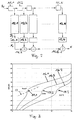
- FIG. 2 shows a block diagram of the signal quality estimator 8. It is assumed that that 1 symbols of a predefined constellation are generated in the transmitter. This Symbols are usually transmitted one after the other, but can also be transmitted simultaneously (e.g. with different frequencies) are transmitted. As part of the following explanations a chronological order is assumed.
- the noise process (which can also be based on interference) can occur in the receiver can be considered as random.
- the disturbances are bundled or impulse-like accepted (English bursty). By that is meant that it is an "ordinary” noise performance (Engl. noise power) there and that this noise power from time to time Time for a short period increases to a very high value, afterwards to the "ordinary” Value falling behind. Both the increase and the duration of the increase the noise performance are random.
- the noise power is determined for each symbol transmitted. Without restricting generality, it can be assumed that the signal power is known (e.g. due to a measurement at the beginning of the reception of a data block). What is wanted, however, is not the current performance of the faults, but the Variance of the noise process at a given time.
- the noise power estimate is based on a block or window of N successive symbols.
- the length N of the window becomes the expected one Noise process selected. Larger window lengths result in constant signal quality for greater accuracy, but for a slower response to changes in the signal quality.
- PLC Powerline Communication
- Symbol rate symbols per second
- the noise level determined with the window becomes for that in the center of the window lying icon used. If N is odd, the result of the signal quality estimate depends of (N-1) / 2 previous and of (N-1) / 2 subsequent demodulated Symbols as well as from the symbol, the quality of which must be valued. (The length N can also be straight; but then the estimation method is not symmetrical. For the However, the performance of the method according to the invention has no negative effects.)
- the invention is primarily intended for situations in which the signal power is essentially constant and the noise performance is variable. If the signal power is also time-varying, but varies more slowly than the noise output, the Invention can also be used, but with an additional computational effort Tracking signal power is required.
- the estimated symbols si are put into a shift register with N delay elements 11.1 to 11.N entered.
- the output of each delay element 11.1 to 11.N is passed on to a computer 12.1 to 12.N.
- BPSK modulation with the two constellation points +1 and -1 for example first determined whether the amount is greater or less than 0. In the former Fall becomes the Euclidean distance Di to the constellation point +1 and in the second If the corresponding distance to the constellation point -1 is calculated.
- adders 14.1 to 14.N-1 calculate the sum of all values xi. Because of From the above, it is clear that the resulting reliability value x is the range of values [0, 1, ..., N].
- the calculation of the quality value entails a delay of (N-1) / 2. Out for this reason there is a delay element in the direct path between demodulator 7 and decoder 8 15 appropriate size to use.
- the first symbol has no predecessors.
- the missing xi will be with zeros initiated, then the quality of the first few symbols is undervalued, they become on the other hand, initialized with the value of the first symbol, this is then overrated.
- the window is therefore at the beginning and at Shortened the end of the symbol stream, for example by only this for the first symbol and the (N + 1) / 2 subsequent symbols are taken into account.
- the quality is based, for example, on (N + 3) / 2 symbol values (namely on the first or last, the second or second last and the following (N + 1) / 2 symbols). It should be noted that the result of the quality estimator should be scaled with a factor A / N (A denotes the number of valid Symbols in the shift register (delay elements 11.1 to 11.N).
- Another possibility consists in closing all the initial values of the quality estimator 8 ignore which are not based on N valid symbols. For the first or last (N + 1) / 2 symbols in this case there are no estimates of the variance of the disturbance process.
- the general block diagram according to FIG. 2 can be simplified depending on the circumstances (e.g. if the demodulated symbols are real and bipolar). At this point but these simplifications will not be discussed in more detail (because they are not essential Influence the result).
- the hump or the S characteristic leads to that the sensitivity of the output signal is less sensitive in a certain range reacts to changes in the SNR, which contributes to inaccuracies in the Measurement of the variance of the disturbance process, i.e. relatively short window lengths, not critical are.
- the S-line characteristic has a lower one (in terms of the working point) Ratio of signal to noise an overestimation based on a linear Comparison line (see e.g. dashed line 18 for characteristic 16.1) and a higher one Ratio of signal to noise a relative undervaluation of the signal quality Episode.
- the method according to the invention for signal / noise ratios in the range of approx. 5 dB to 15 dB is particularly suitable.
- the characteristics should be placed by a suitable choice of the distance parameter D so that the hump in the
- the range of the critical SNR value lies (have modulation and coding methods Usually a small critical area of the SNR: Above this area is the Performance good, below bad. If the noise level increases briefly strongly, the "working point" temporarily shifts to the lower side or Vine of the hump. Under the boundary conditions on which FIG. 3 is based, the Characteristic 16.2 is the most suitable.
- Figures 4a to 4d show simulation results for a packet-oriented data transmission by means of BPSK via the electrical supply lines.
- the data rate was up 15 ms / s set.
- an equalizer and a Convolutional code used to combat channel interference.
- the graphic representations show the packet error rate in the presence of pulse-like (bursty) noise. Compared the performance with and without the quality estimation according to the invention.
- the SNR is 25 dB and the interference pulses have a length of 1 ⁇ s.
- the advantage The invention is distinctive: interference pulses with levels of over 35dB compared to the background noise can be tolerated. If the quality estimate according to the invention is dispensed with a difference of only 20 dB can be accepted.
- the performance of known ones is achieved by the invention
- Signal transmission method in the presence of pulse-like interference the transmission channel can be improved.
- the invention is suitable for any linear modulation method with FEC, in which the coded symbols with a discrete, preferably small number of constellation points coincide.
Landscapes
- Engineering & Computer Science (AREA)
- Computer Networks & Wireless Communication (AREA)
- Signal Processing (AREA)
- Power Engineering (AREA)
- Digital Transmission Methods That Use Modulated Carrier Waves (AREA)
- Detection And Prevention Of Errors In Transmission (AREA)
- Radio Relay Systems (AREA)
- Optical Communication System (AREA)
- Noise Elimination (AREA)
Priority Applications (13)
| Application Number | Priority Date | Filing Date | Title |
|---|---|---|---|
| EP98810582A EP0967761A1 (fr) | 1998-06-24 | 1998-06-24 | Méthode de transmission de données numériques via un canal générant des erreurs par paquets |
| BR9911466-6A BR9911466A (pt) | 1998-06-24 | 1999-05-19 | Procedimento para a transmissão de dados digitais através de um canal de transmissão sujeito a um feixe de perturbações |
| IL14041099A IL140410A0 (en) | 1998-06-24 | 1999-05-19 | Method for transmitting digital data via a transmission channel subject to perturbations occurring in bursts |
| JP2000556484A JP2003512744A (ja) | 1998-06-24 | 1999-05-19 | バースト的に生じる妨害を伴う伝送チャネルを介してディジタルデータを伝送する方法 |
| CN99807839A CN1308808A (zh) | 1998-06-24 | 1999-05-19 | 通过遭受脉冲串干扰的传输信道传输数字数据的方法 |
| CA002335433A CA2335433A1 (fr) | 1998-06-24 | 1999-05-19 | Procede de transmission de donnees numeriques par un canal de transmission affecte par des perturbations survenant en rafales |
| HK02100801.7A HK1039421A1 (zh) | 1998-06-24 | 1999-05-19 | 通過遭受脈冲串干擾的傳輸信道傳輸數字數據的方法 |
| AU36972/99A AU3697299A (en) | 1998-06-24 | 1999-05-19 | Method for transmitting digital data via a transmission channel subject to perturbations occurring in bursts |
| IDW20002682A ID28043A (id) | 1998-06-24 | 1999-05-19 | Metode untuk mengirim data digital melalui saluran pengiriman yang mengalami interferensi yang terjadi dalam ledakan |
| PCT/CH1999/000214 WO1999067929A1 (fr) | 1998-06-24 | 1999-05-19 | Procede de transmission de donnees numeriques par un canal de transmission affecte par des perturbations survenant en rafales |
| KR1020007014405A KR20010071514A (ko) | 1998-06-24 | 1999-05-19 | 버스트에 간섭이 발생하기 쉬운 전송 채널을 경유한디지털 데이터 전송 방법 |
| EP99919020A EP1090489A1 (fr) | 1998-06-24 | 1999-05-19 | Procede de transmission de donnees numeriques par un canal de transmission affecte par des perturbations survenant en rafales |
| NO20006502A NO20006502L (no) | 1998-06-24 | 2000-12-20 | Fremgangsmåte for overföring av digitale data via en overföringskanal som er beheftet med sammenbuntet opptredende forstyrrelser |
Applications Claiming Priority (1)
| Application Number | Priority Date | Filing Date | Title |
|---|---|---|---|
| EP98810582A EP0967761A1 (fr) | 1998-06-24 | 1998-06-24 | Méthode de transmission de données numériques via un canal générant des erreurs par paquets |
Publications (1)
| Publication Number | Publication Date |
|---|---|
| EP0967761A1 true EP0967761A1 (fr) | 1999-12-29 |
Family
ID=8236155
Family Applications (2)
| Application Number | Title | Priority Date | Filing Date |
|---|---|---|---|
| EP98810582A Withdrawn EP0967761A1 (fr) | 1998-06-24 | 1998-06-24 | Méthode de transmission de données numériques via un canal générant des erreurs par paquets |
| EP99919020A Withdrawn EP1090489A1 (fr) | 1998-06-24 | 1999-05-19 | Procede de transmission de donnees numeriques par un canal de transmission affecte par des perturbations survenant en rafales |
Family Applications After (1)
| Application Number | Title | Priority Date | Filing Date |
|---|---|---|---|
| EP99919020A Withdrawn EP1090489A1 (fr) | 1998-06-24 | 1999-05-19 | Procede de transmission de donnees numeriques par un canal de transmission affecte par des perturbations survenant en rafales |
Country Status (12)
| Country | Link |
|---|---|
| EP (2) | EP0967761A1 (fr) |
| JP (1) | JP2003512744A (fr) |
| KR (1) | KR20010071514A (fr) |
| CN (1) | CN1308808A (fr) |
| AU (1) | AU3697299A (fr) |
| BR (1) | BR9911466A (fr) |
| CA (1) | CA2335433A1 (fr) |
| HK (1) | HK1039421A1 (fr) |
| ID (1) | ID28043A (fr) |
| IL (1) | IL140410A0 (fr) |
| NO (1) | NO20006502L (fr) |
| WO (1) | WO1999067929A1 (fr) |
Families Citing this family (4)
| Publication number | Priority date | Publication date | Assignee | Title |
|---|---|---|---|---|
| AU2003903826A0 (en) * | 2003-07-24 | 2003-08-07 | University Of South Australia | An ofdm receiver structure |
| EP1748573B1 (fr) * | 2005-07-29 | 2010-03-31 | Grundfos Management A/S | Méthode pour la transmission de données entre une pompe et une entité de contrôle et pompe correspondante. |
| US9413423B1 (en) * | 2015-08-18 | 2016-08-09 | Texas Instruments Incorporated | SNR calculation in impulsive noise and erasure channels |
| KR101626470B1 (ko) | 2015-09-16 | 2016-06-01 | (주)계림건축사사무소 | 비발포체형 소음 저감재 및 이를 포함하는 바닥구조 |
Citations (3)
| Publication number | Priority date | Publication date | Assignee | Title |
|---|---|---|---|---|
| US4322848A (en) * | 1980-06-26 | 1982-03-30 | Communications Satellite Corporation | Reliability-weighted analog threshold decoder |
| EP0507444A2 (fr) * | 1991-03-07 | 1992-10-07 | Matsushita Electric Industrial Co., Ltd. | Appareil de transmission de données avec calculateur d'erreurs et de probabilité maximale |
| EP0689312A2 (fr) * | 1994-06-21 | 1995-12-27 | NEC Corporation | Récepteur sortant des signaux à décision pondérée |
-
1998
- 1998-06-24 EP EP98810582A patent/EP0967761A1/fr not_active Withdrawn
-
1999
- 1999-05-19 AU AU36972/99A patent/AU3697299A/en not_active Abandoned
- 1999-05-19 WO PCT/CH1999/000214 patent/WO1999067929A1/fr not_active Ceased
- 1999-05-19 HK HK02100801.7A patent/HK1039421A1/zh unknown
- 1999-05-19 BR BR9911466-6A patent/BR9911466A/pt not_active IP Right Cessation
- 1999-05-19 IL IL14041099A patent/IL140410A0/xx unknown
- 1999-05-19 KR KR1020007014405A patent/KR20010071514A/ko not_active Withdrawn
- 1999-05-19 ID IDW20002682A patent/ID28043A/id unknown
- 1999-05-19 EP EP99919020A patent/EP1090489A1/fr not_active Withdrawn
- 1999-05-19 CA CA002335433A patent/CA2335433A1/fr not_active Abandoned
- 1999-05-19 JP JP2000556484A patent/JP2003512744A/ja active Pending
- 1999-05-19 CN CN99807839A patent/CN1308808A/zh active Pending
-
2000
- 2000-12-20 NO NO20006502A patent/NO20006502L/no not_active Application Discontinuation
Patent Citations (3)
| Publication number | Priority date | Publication date | Assignee | Title |
|---|---|---|---|---|
| US4322848A (en) * | 1980-06-26 | 1982-03-30 | Communications Satellite Corporation | Reliability-weighted analog threshold decoder |
| EP0507444A2 (fr) * | 1991-03-07 | 1992-10-07 | Matsushita Electric Industrial Co., Ltd. | Appareil de transmission de données avec calculateur d'erreurs et de probabilité maximale |
| EP0689312A2 (fr) * | 1994-06-21 | 1995-12-27 | NEC Corporation | Récepteur sortant des signaux à décision pondérée |
Also Published As
| Publication number | Publication date |
|---|---|
| IL140410A0 (en) | 2002-02-10 |
| WO1999067929A1 (fr) | 1999-12-29 |
| AU3697299A (en) | 2000-01-10 |
| KR20010071514A (ko) | 2001-07-28 |
| EP1090489A1 (fr) | 2001-04-11 |
| HK1039421A1 (zh) | 2002-04-19 |
| BR9911466A (pt) | 2001-03-20 |
| ID28043A (id) | 2001-05-03 |
| CA2335433A1 (fr) | 1999-12-29 |
| CN1308808A (zh) | 2001-08-15 |
| JP2003512744A (ja) | 2003-04-02 |
| NO20006502L (no) | 2001-02-23 |
| NO20006502D0 (no) | 2000-12-20 |
Similar Documents
| Publication | Publication Date | Title |
|---|---|---|
| DE69732153T2 (de) | Verfahren und Vorrichtung zur Dekodierung von Blockcodes | |
| DE69430894T2 (de) | Schaltung zur Signalqualitätsbestimmung für Empfänger im GSM-System | |
| DE69322022T2 (de) | Verfahren und vorrichtung zur schätzung von wichtungsparametern in einem empfänger | |
| EP1320968B1 (fr) | Correction automatique de frequence pour recepteur de telephonie mobile | |
| EP1130867A2 (fr) | Récepteur et procédé de détection, pour le décodage d'un signal reçu MDPD ä quatre états et à codage de canal | |
| DE2257929A1 (de) | Empfangsanordnung und verfahren zur entzerrung uebertragungsgangbeeinflusster codierter daten | |
| DE102007044488A1 (de) | Empfangsverfahren, Empfangsvorrichtung und Programm | |
| EP0504546B1 (fr) | Méthode d'obtention initiale de la synchronisation de phase et d'adaptation du filtre de réception d'un récepteur numérique dans un système de transmission en bande de base | |
| EP0534399A2 (fr) | Procédé de multiplexage temporel pour déterminer la variation de phase d'un signal de réception | |
| DE1931992A1 (de) | Verfahren zur Impulskorrektion | |
| EP0664625A2 (fr) | Méthode d'estimation de la qualité d'une liaison de transmission | |
| EP1090489A1 (fr) | Procede de transmission de donnees numeriques par un canal de transmission affecte par des perturbations survenant en rafales | |
| EP1210787B1 (fr) | Procede permettant d'evaluer le taux d'erreurs sur les bits dans un recepteur radio et recepteur radio correspondant | |
| EP0545159B1 (fr) | Procédé de transmission radio numérique avec estimation de la résponse impulsionnelle du canal | |
| DE60206538T2 (de) | Empfänger für ein mobiles Funkkommunikationsendgerät | |
| DE4311604C1 (de) | Zuverlässigkeitsgesteuerte Datendetektion in Empfängern für TDMA-Mobilfunksysteme | |
| EP1316182B1 (fr) | Egalisation de canal amelioree pour recepteur de telephonie mobile | |
| EP1252716B1 (fr) | Procede et systeme pour le decodage d'informations | |
| EP1116356B1 (fr) | Dispositif et procede pour la regulation de la cadence d'echantillonnage dans un systeme de transmission de donnees | |
| DE4311655C1 (de) | Kalman-Filter zur Kanalstoßantwortadaption in Empfängern für TDMA-Mobilfunksysteme | |
| DE69732634T2 (de) | Verfahren zur bestimmung der qualität einer verbindung und empfänger | |
| DE2944245C2 (de) | Verfahren und Anordnung zur Vermeidung der Auswertung von Pseudodatentelegrammen | |
| DE69830181T2 (de) | Schwundmarginmessung eines funksystems | |
| DE4427831C2 (de) | Verfahren und Anordnung zur Detektion von Datensymbolen | |
| DE19735752A1 (de) | Verfahren zur Störunterdrückung eines bipolaren Datenstroms und Schaltungsanordnung zur Durchführung des Verfahrens |
Legal Events
| Date | Code | Title | Description |
|---|---|---|---|
| PUAI | Public reference made under article 153(3) epc to a published international application that has entered the european phase |
Free format text: ORIGINAL CODE: 0009012 |
|
| AK | Designated contracting states |
Kind code of ref document: A1 Designated state(s): AT BE CH CY DE DK ES FI FR GB GR IE IT LI LU MC NL PT SE |
|
| AX | Request for extension of the european patent |
Free format text: AL;LT;LV;MK;RO;SI |
|
| AKX | Designation fees paid | ||
| REG | Reference to a national code |
Ref country code: DE Ref legal event code: 8566 |
|
| STAA | Information on the status of an ep patent application or granted ep patent |
Free format text: STATUS: THE APPLICATION IS DEEMED TO BE WITHDRAWN |
|
| 18D | Application deemed to be withdrawn |
Effective date: 19991230 |