EP0967832B1 - Méthode et dispositif pour la délivrance d'énergie électrique à un dispositif actif partiellement implanté - Google Patents
Méthode et dispositif pour la délivrance d'énergie électrique à un dispositif actif partiellement implanté Download PDFInfo
- Publication number
- EP0967832B1 EP0967832B1 EP99112047.8A EP99112047A EP0967832B1 EP 0967832 B1 EP0967832 B1 EP 0967832B1 EP 99112047 A EP99112047 A EP 99112047A EP 0967832 B1 EP0967832 B1 EP 0967832B1
- Authority
- EP
- European Patent Office
- Prior art keywords
- energy converter
- pole
- energy
- implant
- implant wearer
- Prior art date
- Legal status (The legal status is an assumption and is not a legal conclusion. Google has not performed a legal analysis and makes no representation as to the accuracy of the status listed.)
- Expired - Lifetime
Links
Images



Classifications
-
- A—HUMAN NECESSITIES
- A61—MEDICAL OR VETERINARY SCIENCE; HYGIENE
- A61N—ELECTROTHERAPY; MAGNETOTHERAPY; RADIATION THERAPY; ULTRASOUND THERAPY
- A61N1/00—Electrotherapy; Circuits therefor
- A61N1/18—Applying electric currents by contact electrodes
- A61N1/32—Applying electric currents by contact electrodes alternating or intermittent currents
- A61N1/36—Applying electric currents by contact electrodes alternating or intermittent currents for stimulation
- A61N1/372—Arrangements in connection with the implantation of stimulators
- A61N1/378—Electrical supply
-
- H—ELECTRICITY
- H04—ELECTRIC COMMUNICATION TECHNIQUE
- H04R—LOUDSPEAKERS, MICROPHONES, GRAMOPHONE PICK-UPS OR LIKE ACOUSTIC ELECTROMECHANICAL TRANSDUCERS; ELECTRIC HEARING AIDS; PUBLIC ADDRESS SYSTEMS
- H04R25/00—Electric hearing aids
-
- H—ELECTRICITY
- H10—SEMICONDUCTOR DEVICES; ELECTRIC SOLID-STATE DEVICES NOT OTHERWISE PROVIDED FOR
- H10N—ELECTRIC SOLID-STATE DEVICES NOT OTHERWISE PROVIDED FOR
- H10N10/00—Thermoelectric devices comprising a junction of dissimilar materials, i.e. devices exhibiting Seebeck or Peltier effects
-
- H—ELECTRICITY
- H10—SEMICONDUCTOR DEVICES; ELECTRIC SOLID-STATE DEVICES NOT OTHERWISE PROVIDED FOR
- H10N—ELECTRIC SOLID-STATE DEVICES NOT OTHERWISE PROVIDED FOR
- H10N10/00—Thermoelectric devices comprising a junction of dissimilar materials, i.e. devices exhibiting Seebeck or Peltier effects
- H10N10/10—Thermoelectric devices comprising a junction of dissimilar materials, i.e. devices exhibiting Seebeck or Peltier effects operating with only the Peltier or Seebeck effects
- H10N10/17—Thermoelectric devices comprising a junction of dissimilar materials, i.e. devices exhibiting Seebeck or Peltier effects operating with only the Peltier or Seebeck effects characterised by the structure or configuration of the cell or thermocouple forming the device
-
- A—HUMAN NECESSITIES
- A61—MEDICAL OR VETERINARY SCIENCE; HYGIENE
- A61N—ELECTROTHERAPY; MAGNETOTHERAPY; RADIATION THERAPY; ULTRASOUND THERAPY
- A61N1/00—Electrotherapy; Circuits therefor
- A61N1/18—Applying electric currents by contact electrodes
- A61N1/32—Applying electric currents by contact electrodes alternating or intermittent currents
- A61N1/36—Applying electric currents by contact electrodes alternating or intermittent currents for stimulation
- A61N1/36036—Applying electric currents by contact electrodes alternating or intermittent currents for stimulation of the outer, middle or inner ear
- A61N1/36038—Cochlear stimulation
-
- H—ELECTRICITY
- H04—ELECTRIC COMMUNICATION TECHNIQUE
- H04R—LOUDSPEAKERS, MICROPHONES, GRAMOPHONE PICK-UPS OR LIKE ACOUSTIC ELECTROMECHANICAL TRANSDUCERS; ELECTRIC HEARING AIDS; PUBLIC ADDRESS SYSTEMS
- H04R2225/00—Details of deaf aids covered by H04R25/00, not provided for in any of its subgroups
- H04R2225/31—Aspects of the use of accumulators in hearing aids, e.g. rechargeable batteries or fuel cells
-
- H—ELECTRICITY
- H04—ELECTRIC COMMUNICATION TECHNIQUE
- H04R—LOUDSPEAKERS, MICROPHONES, GRAMOPHONE PICK-UPS OR LIKE ACOUSTIC ELECTROMECHANICAL TRANSDUCERS; ELECTRIC HEARING AIDS; PUBLIC ADDRESS SYSTEMS
- H04R2225/00—Details of deaf aids covered by H04R25/00, not provided for in any of its subgroups
- H04R2225/67—Implantable hearing aids or parts thereof not covered by H04R25/606
-
- H—ELECTRICITY
- H04—ELECTRIC COMMUNICATION TECHNIQUE
- H04R—LOUDSPEAKERS, MICROPHONES, GRAMOPHONE PICK-UPS OR LIKE ACOUSTIC ELECTROMECHANICAL TRANSDUCERS; ELECTRIC HEARING AIDS; PUBLIC ADDRESS SYSTEMS
- H04R25/00—Electric hearing aids
- H04R25/60—Mounting or interconnection of hearing aid parts, e.g. inside tips, housings or to ossicles
- H04R25/602—Mounting or interconnection of hearing aid parts, e.g. inside tips, housings or to ossicles of batteries
Definitions
- the invention relates to a device for supplying an at least partially implanted active device, in particular a hearing aid, with electrical energy generated by an implanted thermoelectric energy converter based on the Seebeck effect.
- thermoelectric energy converter The use of the Seebeck effect to provide the electrical energy needed to operate at least partially implantable active systems has so far found no entry into medical practice. This may be due to the fact that the energy values obtainable with the known devices are insufficient, inter alia because the temperature differences available at the thermoelectric energy converter are in any case very small when the energy converter is implanted.
- the US 3,969,149 relates to a thermoelectric microgenerator and discloses all features of the introductory part of claim 1.
- the DE 19530382 A relates to a method and apparatus for generating electric power and the use of the method and apparatus.
- this document describes a thermoelectric energy converter using the Seebeck effect.
- the invention has for its object to provide a device for supplying a partially or fully implanted active device, in particular a hearing aid, with electrical energy, wherein the energy of an implanted, based on the Seebeck - effect thermoelectric energy converter is generated.
- this object is achieved according to the subject matter of claim 1, wober the pol of the energy converter in a region of the body surface, preferably in the skull or neck, the implant carrier is positioned so that it, preferably by heat coupling with one of the large veins or arteries, at least approximately maintained at core temperature, and that the cold pole of the energy converter is held with a close to the body surface near the skin, preferably a lying closest to the body surface cranial or cervical region of the implant carrier in heat coupling ,
- a device for supplying an at least partially implanted active device, in particular a hearing aid, with electrical energy, with an implantable, based on the Seebeck effect thermoelectric energy converter that uses provided by the body of the implant carrier thermal energy is characterized in that the energy converter Having a plurality of mutually electrically coupled individual modules that the shallpol of the energy converter for heat coupling with an at least approximately held at body temperature implantation site in the body surface, especially in the cranial or cervical region, preferably one of the large veins or arteries, the implant carrier is formed and that Cooling pole of the energy converter for heat coupling with a lying as close to the body surface in the outer skin area, preferably as close as possible to the body surface n skull or neck area, the implant carrier is formed.
- the constantly available thermal energy of the body is converted directly into electrical energy.
- the Seebeck effect is the reversal of the well-known Peltier effect, in which the supply of electrical energy in a suitable material pairing a temperature difference is generated at locally different zones of the element.
- the Seebeck effect is achieved e.g. by the constructive pairing of metals, which have as far as possible a distance in the thermoelectric series of voltages. An even more effective utilization of the effect is achieved by the constructive connection of specially doped semiconductor materials.
- the heat pole of the energy converter is held in heat coupling with the sigmoid sinus of the implant carrier, while the cold pole of the energy converter is held in heat coupling behind the outer ear with the mastoid region of the implant carrier adjacent to the sigmoid sinus close to the body surface.
- Electrical energy generated by the energy converter may be collected in an implantable memory array and latched until needed by the at least partially implanted active device.
- a typical application example is "on-demand” pacemakers, which work most of the time in “standby mode” and only need a few ⁇ W there; If necessary, a short, high-energy stimulus pulse in the mWatt range for cardiac stimulation is generated.
- Other neurostimulators can also be supplied in such a way that they require higher operating energy for short stimulus impulses only at irregular and larger time intervals.
- Provided downstream electrical storage media such as long - life capacitors (Gold - Cap, OSCON capacitors or high quality solid electrolyte tantalum capacitors) and electronic energy management systems provide a short - term power demand peak for neurostimulation in the power range of a few mWatt, when these stimuli are present in the larger one time interval. Furthermore, with small systems of already a few Seebeck elements, a secondary battery cell (accumulator) can be charged, which then provides the temporarily distributed energy demand.
- long - life capacitors Gold - Cap, OSCON capacitors or high quality solid electrolyte tantalum capacitors
- electronic energy management systems provide a short - term power demand peak for neurostimulation in the power range of a few mWatt, when these stimuli are present in the larger one time interval. Furthermore, with small systems of already a few Seebeck elements, a secondary battery cell (accumulator) can be charged, which then provides the temporarily distributed energy demand.
- the intermediate storage of the electrical energy generated by the energy converter in the implantable memory arrangement and / or the energy transfer to the consumer can be conveniently controlled by an implantable control unit, such as a microprocessor or microcontroller, the corresponding peripheral hardware (AD and DA converter, Power actuators and the like) is assigned and in turn requires very little electrical operating power, since usually no time-rapid operations must be processed.
- an implantable control unit such as a microprocessor or microcontroller
- the corresponding peripheral hardware (AD and DA converter, Power actuators and the like) is assigned and in turn requires very little electrical operating power, since usually no time-rapid operations must be processed.
- the implantable control unit can in particular via a data interface wirelessly, transcutaneously from outside the body of the implant carrier via a corresponding be programmable external control arrangement in order to adapt the overall system "programmable thermoelectric energy converter" to the selected in the specific application and combination case active implant as a consumer.
- the energy converter preferably has a plurality of individual modules electrically coupled to each other, each individual module is provided with two legs of different electrically conductive materials, one end of which is thermally conductively connected to the cold pole and the other end to the choirpol of the energy converter.
- the structure of the energy converter and its manufacturing method can make use of features known per se, such as the others below U.S. Patent 4,095,998 . U.S. Patent 5,439,528 . U.S. Patent 5,430,322 . JP 09 092 889 A . EP 0 731 513 . WO 94/16464 . WO 96/15412 and WO 97/44993 are known.
- the legs of the individual modules can in particular consist of semiconductor materials with n-type or p-type doping or of different metals at a large distance in the thermoelectric voltage series.
- Suitable material combinations for the Seebeck elements include germanium-silicon mixed crystals and bismuth-tellurium combinations as semiconductor elements with suitably chosen doping.
- Other fundamentally suitable material combinations are, inter alia, in WO 94/14200 .
- the cold pole and the bankspol are advantageously made of biocompatible, good heat conducting material.
- biocompatible, good heat conducting material In particular, pure titanium, titanium alloys, niobium, niobium alloys, tantalum, tantalum alloys, stainless steels and ceramic materials such as alumina ceramics are suitable.
- the individual modules are expediently mechanically connected to one another by a biocompatible thermal insulator arranged between the cold pole and the heat pole, wherein the material of the thermally insulating composite element is preferably selected from the group consisting of polytetrafluoroethylene, polycarbonates, polyurethane, silicones and carbon fiber-reinforced polymers.
- the thermally insulating composite element can fill in the manufacturing technology particularly simple way remaining between the individual modules, the cold and the furnishedpol gaps in the form of potting.
- the hermetic gas-tightness which is otherwise required in active implants containing microelectronics is not absolutely necessary in the present case of application, especially if small volumes of water vapor do not damage the Seebeck module internally in the long term and, on the other hand, can not release any toxic substances into the body.
- the potting material can therefore also be good body-compatible silicone.
- the energy converter has a plurality of module groups of individual modules electrically connected in series with one another, wherein these module groups are in turn electrically connected in parallel.
- a large number in the range of more than 100,000
- miniaturized Seebeck elements by, for example, microsystem technology or semiconductor lithographic processes, an overall system can be realized by corresponding electrical series-parallel connection and combination of the individual elements into module groups, with an assessable module area in the range of 100 to 300 cm 2 and a temperature difference of 0.5 K can continuously deliver electrical power in the range of 1 to 3 mWatt at a terminal voltage of 1 to 2 volts.
- the electrical source impedance can be in a range of 100 to 300 ⁇ , so that a continuously operating, sensory implant, in particular hearing aids, can be energetically supplied.
- the cold pole can either itself form a large-area heat sink that can be positioned directly under the skin of the implant carrier or can be heat-conductively coupled to such a heat sink, which leads to an increased temperature difference.
- the energy converter can basically assume any geometric form. Especially with relatively small modules, it can be flat and flat.
- a curved element is preferable in particular in the preferred head region and the mastoid region, which is expedient only a few mm thick and corresponds to a Kalottenabêt that is optimally adapted to the curved head surface.
- thermoelectric energy converter can form a unit with the intended active implant and thereby represent an implant-ready overall module.
- Active, electronic hearing implants that stimulate the inner ear with direct electrical stimulation (fully implantable cochlear implant) should be mentioned here (see for example EP 0 076 070 and EP 0 124 930 ), or rehabilitate partial damage of the inner ear with mechanical stimulation of the middle or inner ear (inner ear hearing loss).
- Systems of the latter type are known, inter alia EP 0 400 630 Federation EP 0 499 940 B.
- thermoelectric energy converter can also be designed as an independent implant, from the electrical output, for example via a suitable two-pin connector and an adequate electrical supply, the electrical energy is supplied to the consumer implant, which need not necessarily be positioned at the same implantation site (typical Example: thermoelectric energy converter in the mastoid, electrical supply through the neck, consumer is pacemaker or other neurostimulator in the chest or abdominal area).
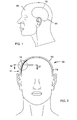
- thermoelectric energy converter 10 based on the Seebeck effect is implanted in the mastoid region 11 of the head 12 of a patient just below the skin, that is to say between the scalp 13 and the skull 14.
- the energy converter 10 has a heat pole 15 and a cold pole 16.
- the heat pole 15 is in the illustrated embodiment with the sigmoid sinusoid 17 ( Fig. 4 ) of the implant carrier is held in thermal coupling while the cold pole 16 of the energy converter is held in thermal coupling with the mastoid region 11 adjacent to the sigmoid sinus near the body surface.
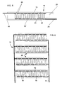
- the energy converter 10 is provided with a plurality n of Seebeck elements or individual modules 20 electrically coupled to each other.
- Each individual module has two legs 21, 22 of different electrically conductive materials, one end of which is thermally conductively connected to the cold pole 16 and the other end to the heat pole 15 of the energy converter 10.
- the individual modules 20 are mechanically connected to one another by a thermally insulating composite element 23 of biocompatible material arranged between the cold pole 16 and the heat pole 15.
- the thermally insulating composite element 23 is shown as a separating layer between the hot and cold.
- the thermally insulating composite member 23 in the form of potting material, which fills the remaining between the individual modules 20, the cooling pole 16 and the heat pole 15 spaces.
- the electrical connection poles are designated by 24.
- the energy converter 10 has a plurality of module groups 25 of individual modules 20 that are electrically connected in series with one another. These module groups 25 are themselves connected in parallel with each other electrically.
- an energy storage 27 connected, which can be constructed in particular of durable capacitors and equipped with a known per se electronic energy management system.
- an implantable electrochemical secondary element 32 may be provided, which is charged by the energy converter 10 directly or via the energy storage 27 when the device 26 unused electrical energy from the energy converter 10 is available, and if necessary electrical Energy to the device 26 outputs.
- Fig. 8 1 shows an embodiment in which an implantable control unit 28 is additionally provided, whose task is to regulate the intermediate storage of the electrical energy generated by the energy converter 10 in the implanted storage arrangement 27 and / or the energy transfer to the device 26 via an electrical connection 29 ,
- the control unit 28 can in turn be controlled and / or programmed by means of an external control and / or programming arrangement 31 via a transcutaneous data path 30 from outside the body of the implant carrier.
- the energy converter 10, the storage arrangement 27 and the control unit 28 are combined to form a first implant 33, while the device 26 forms a second implant 34 which is connected to the first implant 33 via the electrical connection 29.
- Fig. 9 shows an exemplary embodiment in which the energy converter 10, the storage arrangement 27, the control unit 28 and the device 26 are integrated in a single implant 35 and in which by means of the control unit 28 not only the storage arrangement 27 but also the device 26 is controlled and / or or programmed.
- the device 26 is a stimulus generator, its output 36 may be connected to a corresponding stimulus electrode.
Landscapes
- Health & Medical Sciences (AREA)
- Engineering & Computer Science (AREA)
- General Health & Medical Sciences (AREA)
- Biomedical Technology (AREA)
- Radiology & Medical Imaging (AREA)
- Otolaryngology (AREA)
- Acoustics & Sound (AREA)
- Signal Processing (AREA)
- Neurosurgery (AREA)
- Nuclear Medicine, Radiotherapy & Molecular Imaging (AREA)
- Physics & Mathematics (AREA)
- Life Sciences & Earth Sciences (AREA)
- Animal Behavior & Ethology (AREA)
- Public Health (AREA)
- Veterinary Medicine (AREA)
- Prostheses (AREA)
- Electrotherapy Devices (AREA)
Claims (20)
- Dispositif d'alimentation en énergie électrique d'un appareil actif (26) au moins partiellement implanté, en particulier une audioprothèse, qui comporte un convertisseur d'énergie thermoélectrique implantable dont le fonctionnement est basé sur l'effet Seebeck (10) et qui utilise l'énergie thermique produite par le corps du porteur de prothèse,
caractérisé
en ce que le convertisseur d'énergie (10) est constitué de telle façon qu'il peut être introduit de manière conforme entre l'os et la peau correspondante, et comporte une pluralité de modules individuels (20) accouplés électriquement entre eux,
en ce qu'un pôle chaud (15) du convertisseur d'énergie est constitué pour un accouplement calorifique avec une source d'énergie calorifique correspondant à un emplacement d'implantation maintenu au moins approximativement à la température corporelle interne dans la zone de la surface du corps du porteur de prothèse, en particulier dans la zone du crâne ou du cou,
en ce qu'un pôle froid (16) du convertisseur d'énergie est constitué pour un accouplement calorifique avec un dissipateur thermique correspondant à une zone du porteur de prothèse se trouvant plus proche de la surface externe de la peau, en particulier dans la zone du crâne ou du cou, et
en ce que chaque module individuel (20) comporte une extrémité qui est connectée au pôle chaud (15) et une autre extrémité qui est connectée au pôle froid (16). - Dispositif selon la revendication 1, caractérisé en ce que le pôle chaud (15) du convertisseur d'énergie (10) est constitué pour un accouplement calorifique avec une des grosses veines (17) ou artères présentes dans la zone du crâne ou du cou du porteur de prothèse.
- Dispositif selon la revendication 2, caractérisé en ce que le pôle chaud (15) du convertisseur d'énergie (10) est constitué pour un accouplement calorifique avec le sinus sigmoïde (17) du porteur de prothèse et en ce que le pôle froid (16) du convertisseur d'énergie est constitué pour un accouplement calorifique avec la région mastoïde (11) du porteur de prothèse, située près de la surface du corps et adjacente au sinus sigmoïde.
- Dispositif selon l'une des revendications 1 à 3, caractérisé en ce que le pôle froid (16) constitue un corps de refroidissement de grande surface positionnable directement sous la peau du porteur de prothèse.
- Dispositif selon l'une des revendications 1 à 3, caractérisé en ce que le pôle froid (16) est accouplé thermiquement à un corps de refroidissement de grande surface positionnable sous la peau du porteur de prothèse.
- Dispositif selon l'une des revendications 1 à 5, caractérisé par un ensemble de stockage implantable (27) pour collecter et stocker temporairement l'énergie électrique produite par le convertisseur d'énergie (10).
- Dispositif selon la revendication 6, caractérisé par une unité de commande implantable (28) pour réguler le stockage temporaire de l'énergie électrique produite par le convertisseur d'énergie (10) dans l'ensemble de stockage implanté (27) et/ou la transmission de l'énergie à l'appareil actif (26).
- Dispositif selon la revendication 7, caractérisé en ce que l'unité de commande implantable (28) comporte un microprocesseur ou un microcontrôleur.
- Dispositif selon la revendication 7 ou 8, caractérisé par un ensemble externe de commande et/ou de programmation (31) pour commander et/ou programmer l'unité de commande implantable (28) depuis l'extérieur du corps du porteur de prothèse via une ligne de données transcutanée (30).
- Dispositif selon l'une des revendications 1 à 9, caractérisé en ce que chaque module individuel (20) comporte deux jambes (21, 22) constituées en des matériaux qui présentent des conductivités électriques différentes.
- Dispositif selon la revendication 10, caractérisé en ce que les jambes (21, 22) des modules individuels (20) sont constituées en matériaux semiconducteurs à dopage respectivement n et p, ou de métaux différents qui sont fortement éloignés entre eux dans la plage de tension thermoélectrique.
- Dispositif selon l'une des revendications 1 à 11, caractérisé en ce que le pôle froid (16) et le pôle chaud (15) sont constitués en un matériau biocompatible et bon conducteur de la chaleur.
- Dispositif selon la revendication 12, caractérisé en ce que le matériau du pôle froid (16) et du pôle chaud (15) est sélectionné parmi le groupe constitué par le titane pur, les alliages de titane, le niobium, les alliages de niobium, le tantale, les alliages de tantale, les aciers spéciaux et les céramiques d'alumine.
- Dispositif selon l'une des revendications 1 à 13, caractérisé en ce que les modules individuels (20) sont connectés mécaniquement entre eux par un élément de connexion isolant thermique (23) agencé entre le pôle froid (16) et le pôle chaud (15) et constitué en un matériau biocompatible.
- Dispositif selon la revendication 14, caractérisé en ce que le matériau de l'élément de connexion isolant thermique (23) est sélectionné parmi le groupe constitué par le polytétrafluoroéthylène, les polycarbonates, le polyuréthane, les silicones et les polymères à renfort de fibre de carbone.
- Dispositif selon la revendication 14 ou 15, caractérisé en ce que l'élément de connexion isolant thermique (23) remplit les interstices restant entre les modules individuels (20), le pôle froid (16) et le pôle chaud (15) sous forme d'un matériau d'enrobage.
- Dispositif selon l'une des revendications 1 à 16, caractérisé en ce que le convertisseur d'énergie (10) comporte une pluralité de groupes modulaires (25) constitués de modules individuels (20) connectés électriquement entre eux en série, et en ce que ces groupes modulaires sont à leur tour connectés électriquement en parallèle.
- Dispositif selon l'une des revendications 1 à 17, caractérisé en ce que le convertisseur d'énergie (10) est construit de façon plane.
- Dispositif selon la revendication 18, caractérisé en ce que le convertisseur d'énergie (10) est incurvé pour s'adapter à la surface incurvée du corps du porteur de prothèse,
- Dispositif selon la revendication 1, caractérisé en ce qu'une forme du convertisseur d'énergie (10) est essentiellement incurvée pour correspondre généralement à la surface incurvée du corps.
Applications Claiming Priority (2)
| Application Number | Priority Date | Filing Date | Title |
|---|---|---|---|
| DE19827898 | 1998-06-23 | ||
| DE19827898A DE19827898C1 (de) | 1998-06-23 | 1998-06-23 | Verfahren und Vorrichtung zur Versorgung eines teil- oder vollimplantierten aktiven Gerätes mit elektrischer Energie |
Publications (3)
| Publication Number | Publication Date |
|---|---|
| EP0967832A2 EP0967832A2 (fr) | 1999-12-29 |
| EP0967832A3 EP0967832A3 (fr) | 2006-05-10 |
| EP0967832B1 true EP0967832B1 (fr) | 2013-07-31 |
Family
ID=7871726
Family Applications (1)
| Application Number | Title | Priority Date | Filing Date |
|---|---|---|---|
| EP99112047.8A Expired - Lifetime EP0967832B1 (fr) | 1998-06-23 | 1999-06-22 | Méthode et dispositif pour la délivrance d'énergie électrique à un dispositif actif partiellement implanté |
Country Status (3)
| Country | Link |
|---|---|
| US (1) | US6131581A (fr) |
| EP (1) | EP0967832B1 (fr) |
| DE (1) | DE19827898C1 (fr) |
Families Citing this family (44)
| Publication number | Priority date | Publication date | Assignee | Title |
|---|---|---|---|---|
| DE19915684B4 (de) * | 1999-04-07 | 2005-12-01 | Phonak Ag | Implantierbares Positionier- und Fixiersystem für aktorische und sensorische Implantate |
| DE10018361C2 (de) | 2000-04-13 | 2002-10-10 | Cochlear Ltd | Mindestens teilimplantierbares Cochlea-Implantat-System zur Rehabilitation einer Hörstörung |
| DE10018360C2 (de) | 2000-04-13 | 2002-10-10 | Cochlear Ltd | Mindestens teilimplantierbares System zur Rehabilitation einer Hörstörung |
| DE10018334C1 (de) * | 2000-04-13 | 2002-02-28 | Implex Hear Tech Ag | Mindestens teilimplantierbares System zur Rehabilitation einer Hörstörung |
| DE10031832C2 (de) * | 2000-06-30 | 2003-04-30 | Cochlear Ltd | Hörgerät zur Rehabilitation einer Hörstörung |
| DE10041726C1 (de) | 2000-08-25 | 2002-05-23 | Implex Ag Hearing Technology I | Implantierbares Hörsystem mit Mitteln zur Messung der Ankopplungsqualität |
| DE10046938A1 (de) | 2000-09-21 | 2002-04-25 | Implex Ag Hearing Technology I | Mindestens teilimplantierbares Hörsystem mit direkter mechanischer Stimulation eines lymphatischen Raums des Innenohres |
| DE10137504A1 (de) * | 2001-07-31 | 2003-02-27 | Enocean Gmbh | Thermisch antreibbare Spannungsversorgung |
| DE10154923A1 (de) * | 2001-11-08 | 2003-06-05 | Klaus Palme | Verfahren zur Gewinnung elektrischer Energie aus den Temperaturschwankungen der Luft |
| US6640137B2 (en) * | 2002-03-15 | 2003-10-28 | Biomed Solutions Llc | Biothermal power source for implantable devices |
| US7822480B2 (en) * | 2002-06-28 | 2010-10-26 | Boston Scientific Neuromodulation Corporation | Systems and methods for communicating with an implantable stimulator |
| US7437193B2 (en) | 2002-06-28 | 2008-10-14 | Boston Scientific Neuromodulation Corporation | Microstimulator employing improved recharging reporting and telemetry techniques |
| US20050256549A1 (en) * | 2002-10-09 | 2005-11-17 | Sirius Implantable Systems Ltd. | Micro-generator implant |
| ATE469670T1 (de) * | 2002-12-09 | 2010-06-15 | Medtronic Inc | Verbindungsmodul für eine modulare implantierbare medizinische vorrichtung |
| US7596408B2 (en) | 2002-12-09 | 2009-09-29 | Medtronic, Inc. | Implantable medical device with anti-infection agent |
| US7317947B2 (en) * | 2003-05-16 | 2008-01-08 | Medtronic, Inc. | Headset recharger for cranially implantable medical devices |
| US7263401B2 (en) | 2003-05-16 | 2007-08-28 | Medtronic, Inc. | Implantable medical device with a nonhermetic battery |
| US20050004637A1 (en) * | 2003-05-16 | 2005-01-06 | Ruchika Singhal | Explantation of implantable medical device |
| US7596399B2 (en) | 2004-04-29 | 2009-09-29 | Medtronic, Inc | Implantation of implantable medical device |
| US20050245984A1 (en) | 2004-04-30 | 2005-11-03 | Medtronic, Inc. | Implantable medical device with lubricious material |
| WO2006017226A1 (fr) * | 2004-07-12 | 2006-02-16 | Cochlear Americas | Source d'alimentation thermoelectrique |
| JP4330541B2 (ja) * | 2005-01-31 | 2009-09-16 | ヤマハ株式会社 | 体温利用発電装置およびそれを用いた人工内耳システム |
| DE102005032291B3 (de) * | 2005-07-11 | 2006-12-21 | Siemens Audiologische Technik Gmbh | Hörvorrichtung mit thermoelektrischem Wandler |
| WO2007102937A2 (fr) * | 2006-01-13 | 2007-09-13 | Cernasov Andre N | appareil et procédé permettant d'alimenter des dispositifs implantés de manière sous-cutanée |
| US8039727B2 (en) * | 2006-04-26 | 2011-10-18 | Cardiac Pacemakers, Inc. | Method and apparatus for shunt for in vivo thermoelectric power system |
| WO2007127831A2 (fr) * | 2006-04-26 | 2007-11-08 | Cardiac Pacemakers, Inc. | Systeme a energie thermoelectrique implantable |
| US8538529B2 (en) * | 2006-04-26 | 2013-09-17 | Cardiac Pacemakers, Inc. | Power converter for use with implantable thermoelectric generator |
| US8003879B2 (en) | 2006-04-26 | 2011-08-23 | Cardiac Pacemakers, Inc. | Method and apparatus for in vivo thermoelectric power system |
| US9084901B2 (en) | 2006-04-28 | 2015-07-21 | Medtronic, Inc. | Cranial implant |
| JP2008048067A (ja) * | 2006-08-11 | 2008-02-28 | Matsushita Electric Works Ltd | 補聴器 |
| EP2124267A3 (fr) * | 2008-05-22 | 2012-02-01 | Stichting IMEC Nederland | Générateur thermoélectrique pour implants et dispositifs intégrés |
| US8948870B2 (en) | 2008-09-09 | 2015-02-03 | Incube Labs, Llc | Energy harvesting mechanism |
| US9026212B2 (en) * | 2008-09-23 | 2015-05-05 | Incube Labs, Llc | Energy harvesting mechanism for medical devices |
| US9393432B2 (en) | 2008-10-31 | 2016-07-19 | Medtronic, Inc. | Non-hermetic direct current interconnect |
| CN102347715A (zh) * | 2010-08-02 | 2012-02-08 | 余哲锐 | 显示温差效应的手温发电装置 |
| WO2012031282A2 (fr) * | 2010-09-03 | 2012-03-08 | Tufts University/Trustees Of Tufts College | Matériaux à base de soie dopés aux nanoparticules plasmoniques |
| US9084859B2 (en) | 2011-03-14 | 2015-07-21 | Sleepnea Llc | Energy-harvesting respiratory method and device |
| PL2506600T3 (pl) * | 2011-04-01 | 2016-12-30 | Zasilacz dla aparatu słuchowego lub układu wspomagania słuchu | |
| TWI513485B (zh) * | 2012-08-15 | 2015-12-21 | Nat Univ Tsing Hua | 微型植入裝置 |
| WO2016073944A1 (fr) * | 2014-11-06 | 2016-05-12 | The Regents Of The University Of California | Plateforme de récupération d'énergie thermoélectrique autonome pour capteurs biomédicaux |
| JP2019503722A (ja) | 2015-11-17 | 2019-02-14 | インスパイア・メディカル・システムズ・インコーポレイテッドInspire Medical Systems, Inc. | 睡眠呼吸障害(sdb)微小刺激治療装置 |
| US20190134408A1 (en) * | 2017-11-07 | 2019-05-09 | Qualcomm Incorporated | Cyclic heating and cooling of skin to power thermionic implant |
| FR3081616B1 (fr) * | 2018-05-24 | 2020-06-12 | Universite Grenoble Alpes | Generateur thermoelectrique, dispositif implantable et procede associes |
| US20230140563A1 (en) * | 2020-03-20 | 2023-05-04 | Moroz Technologies Pty Ltd. | System and method for thermoelectric charging of a battery |
Family Cites Families (29)
| Publication number | Priority date | Publication date | Assignee | Title |
|---|---|---|---|---|
| US2798493A (en) * | 1954-06-09 | 1957-07-09 | Sukacev Lev | Devices for transferring thermoelectric power effects to the skin of a human |
| FR92782E (fr) * | 1965-10-13 | 1968-12-27 | Massiot Philips Sa | Stimulateur cardiaque. |
| FR2044246A5 (fr) * | 1969-05-13 | 1971-02-19 | Philips Massiot Mat Medic | |
| DE2200054C3 (de) | 1972-01-03 | 1978-09-14 | Siemens Ag, 1000 Berlin Und 8000 Muenchen | Implantierbare Biobrennstoffzelle |
| DE2415385A1 (de) * | 1974-03-29 | 1975-10-02 | Siemens Ag | Herzschrittmacher |
| US4095998A (en) * | 1976-09-30 | 1978-06-20 | The United States Of America As Represented By The Secretary Of The Army | Thermoelectric voltage generator |
| US4134408A (en) * | 1976-11-12 | 1979-01-16 | Research Corporation | Cardiac pacer energy conservation system |
| DE2729223C3 (de) * | 1977-06-29 | 1981-01-15 | Eberhard Prof. Dr.Rer.Nat. 6600 Saarbruecken Haeusler | Anordnung zum Umwandeln physiologisch erzeugter mechanischer Energie in elektrische Energie |
| CH613087B (de) * | 1978-05-10 | Bulova Watch Co Inc | Thermoelektrische armbanduhr. | |
| US4441210A (en) * | 1981-09-18 | 1984-04-03 | Hochmair Erwin S | Transcutaneous signal transmission system and methods |
| US4532930A (en) * | 1983-04-11 | 1985-08-06 | Commonwealth Of Australia, Dept. Of Science & Technology | Cochlear implant system for an auditory prosthesis |
| US4961230B1 (en) * | 1988-05-10 | 1997-12-23 | Minnesota Mining & Mfg | Hearing aid programming interface |
| DE3940632C1 (en) * | 1989-06-02 | 1990-12-06 | Hortmann Gmbh, 7449 Neckartenzlingen, De | Hearing aid directly exciting inner ear - has microphone encapsulated for implantation in tympanic cavity or mastoid region |
| DE4104359A1 (de) * | 1991-02-13 | 1992-08-20 | Implex Gmbh | Ladesystem fuer implantierbare hoerhilfen und tinnitus-maskierer |
| DE4104358A1 (de) * | 1991-02-13 | 1992-08-20 | Implex Gmbh | Implantierbares hoergeraet zur anregung des innenohres |
| US5356485A (en) * | 1992-04-29 | 1994-10-18 | The United States Of America As Represented By The Secretary Of Commerce | Intermetallic thermocouples |
| JP2636119B2 (ja) * | 1992-09-08 | 1997-07-30 | 工業技術院長 | 熱電素子シートとその製造方法 |
| WO1994014200A1 (fr) * | 1992-12-11 | 1994-06-23 | Joel Miller | Thermoelement stratifie |
| US5439528A (en) * | 1992-12-11 | 1995-08-08 | Miller; Joel | Laminated thermo element |
| US5422813A (en) * | 1992-12-17 | 1995-06-06 | Stanford Telecommunications, Inc. | No-outage GPS/commercial RF positioning system |
| US5393351A (en) * | 1993-01-13 | 1995-02-28 | The United States Of America As Represented By The Secretary Of Commerce | Multilayer film multijunction thermal converters |
| US5610366A (en) * | 1993-08-03 | 1997-03-11 | California Institute Of Technology | High performance thermoelectric materials and methods of preparation |
| US5892656A (en) * | 1993-10-19 | 1999-04-06 | Bass; John C. | Thermoelectric generator |
| JPH0829559A (ja) * | 1994-07-20 | 1996-02-02 | Seiko Instr Inc | 電子時計 |
| CZ281281B6 (cs) * | 1994-11-08 | 1996-08-14 | Zdeněk Ing. Csc. Starý | Kaskáda termoelektrických článků využívající Peltierův jev |
| DE69610516T2 (de) * | 1995-03-09 | 2001-05-17 | Nisshin Steel Co., Ltd. | Thermoelektrischer Leistungsgenerator unter Verwendung von porösen Metallblöcken mit einer Anzahl von Thermoelementen in Serienschaltung |
| DE19530382A1 (de) * | 1995-08-18 | 1997-02-20 | Meiners Horst | Verfahren und Vorrichtung zum Erzeugen von elektrischem Strom und Verwendung des Verfahrens und der Vorrichtung |
| US5810015A (en) * | 1995-09-01 | 1998-09-22 | Strato/Infusaid, Inc. | Power supply for implantable device |
| JP2728201B2 (ja) * | 1995-09-26 | 1998-03-18 | 京都大学長 | ゼーベック素子 |
-
1998
- 1998-06-23 DE DE19827898A patent/DE19827898C1/de not_active Expired - Fee Related
-
1999
- 1999-06-14 US US09/332,605 patent/US6131581A/en not_active Expired - Lifetime
- 1999-06-22 EP EP99112047.8A patent/EP0967832B1/fr not_active Expired - Lifetime
Also Published As
| Publication number | Publication date |
|---|---|
| DE19827898C1 (de) | 1999-11-11 |
| EP0967832A2 (fr) | 1999-12-29 |
| US6131581A (en) | 2000-10-17 |
| EP0967832A3 (fr) | 2006-05-10 |
Similar Documents
| Publication | Publication Date | Title |
|---|---|---|
| EP0967832B1 (fr) | Méthode et dispositif pour la délivrance d'énergie électrique à un dispositif actif partiellement implanté | |
| DE69826675T2 (de) | Implantierbare einrichtung mit verbesserter anordnung zur ladung der batterie und zur energiezufuhr | |
| DE60107062T2 (de) | Vollständig implantierbare cochlea-microprothese mit einer vielzahl von kontakten | |
| AT507045B1 (de) | Implantierbare, gewebe-stimulierende vorrichtung | |
| DE60214752T2 (de) | Multiplexierte steuerungseinheit für elektrodenmatrizen | |
| DE19837913C2 (de) | Implantierbare Vorrichtung mit einer eine Empfangsspule aufweisenden Ladestromeinspeiseanordnung | |
| US7532936B2 (en) | Programmable switching device for implantable device | |
| DE69825969T2 (de) | Implantierbare elektrode zur nervenstimulation | |
| DE60310130T2 (de) | Therapeutische signale direkt übertragendes extern aktiviertes neuroimplantat | |
| US8750985B2 (en) | Low power loss current digital-to-analog converter used in an implantable pulse generator | |
| DE102006033623B4 (de) | System zur transkutanen Stimulation eines Nervs des menschlichen Körpers | |
| EP2608840B1 (fr) | Électrode pour utilisations médicales, système comportant une électrode et procédé de fabrication d'une électrode | |
| US20140155957A1 (en) | Connector assemblies for implantable stimulators | |
| DE3008677A1 (de) | Verfahren zur elektrischen stimulation des hoernervs und multikanal-hoerprothese zur durchfuehrung des verfahrens | |
| DE2823798C2 (de) | Verfahren zur elektrischen Stimulation des Hörnervs und Multikanal-Hörprothese zur Durchführung des Verfahrens | |
| AT502325A1 (de) | Laminierte elektrode für ein cochlea-implantat | |
| WO2008089726A1 (fr) | Implant pour stimuler des cellules nerveuses | |
| WO1998026836A1 (fr) | Systeme d'electrodes de stimulation | |
| DE602005002498T2 (de) | Gehirnimplantat | |
| DE112018000546T5 (de) | Verfahren und Vorrichtung zur Energiegewinnung unter Verwendung polymerer piezoelektrischer Strukturen | |
| DE10294019B4 (de) | Neurostimulator sowie Datenübertragungsverfahren | |
| EP3476432B1 (fr) | Dispositif de thérapie de haute tension | |
| Troyk et al. | Sensory neural prostheses | |
| DE19632705A1 (de) | Vorrichtung zur Stimulation der Corpora Cavernosi Penis | |
| WO2008113091A1 (fr) | Système de stimulation électrique de muscles ou de nerfs |
Legal Events
| Date | Code | Title | Description |
|---|---|---|---|
| PUAI | Public reference made under article 153(3) epc to a published international application that has entered the european phase |
Free format text: ORIGINAL CODE: 0009012 |
|
| AK | Designated contracting states |
Kind code of ref document: A2 Designated state(s): AT BE CH CY DE DK ES FI FR GB GR IE IT LI LU MC NL PT SE |
|
| AX | Request for extension of the european patent |
Free format text: AL;LT;LV;MK;RO;SI |
|
| RAP1 | Party data changed (applicant data changed or rights of an application transferred) |
Owner name: COCHLEAR LIMITED |
|
| PUAL | Search report despatched |
Free format text: ORIGINAL CODE: 0009013 |
|
| AK | Designated contracting states |
Kind code of ref document: A3 Designated state(s): AT BE CH CY DE DK ES FI FR GB GR IE IT LI LU MC NL PT SE |
|
| AX | Request for extension of the european patent |
Extension state: AL LT LV MK RO SI |
|
| 17P | Request for examination filed |
Effective date: 20061108 |
|
| AKX | Designation fees paid |
Designated state(s): AT DE FR GB |
|
| 17Q | First examination report despatched |
Effective date: 20071017 |
|
| REG | Reference to a national code |
Ref country code: DE Ref legal event code: R079 Ref document number: 59915383 Country of ref document: DE Free format text: PREVIOUS MAIN CLASS: H04R0025000000 Ipc: A61F0002180000 |
|
| GRAP | Despatch of communication of intention to grant a patent |
Free format text: ORIGINAL CODE: EPIDOSNIGR1 |
|
| RIC1 | Information provided on ipc code assigned before grant |
Ipc: A61N 1/28 20060101ALI20130110BHEP Ipc: H01L 35/00 20060101ALI20130110BHEP Ipc: A61N 1/24 20060101ALI20130110BHEP Ipc: A61F 2/18 20060101AFI20130110BHEP Ipc: A61N 1/378 20060101ALI20130110BHEP Ipc: H01L 35/32 20060101ALI20130110BHEP |
|
| GRAS | Grant fee paid |
Free format text: ORIGINAL CODE: EPIDOSNIGR3 |
|
| GRAA | (expected) grant |
Free format text: ORIGINAL CODE: 0009210 |
|
| AK | Designated contracting states |
Kind code of ref document: B1 Designated state(s): AT DE FR GB |
|
| REG | Reference to a national code |
Ref country code: GB Ref legal event code: FG4D Free format text: NOT ENGLISH |
|
| REG | Reference to a national code |
Ref country code: AT Ref legal event code: REF Ref document number: 624163 Country of ref document: AT Kind code of ref document: T Effective date: 20130815 |
|
| REG | Reference to a national code |
Ref country code: DE Ref legal event code: R096 Ref document number: 59915383 Country of ref document: DE Effective date: 20130926 |
|
| PLBE | No opposition filed within time limit |
Free format text: ORIGINAL CODE: 0009261 |
|
| STAA | Information on the status of an ep patent application or granted ep patent |
Free format text: STATUS: NO OPPOSITION FILED WITHIN TIME LIMIT |
|
| 26N | No opposition filed |
Effective date: 20140502 |
|
| PGFP | Annual fee paid to national office [announced via postgrant information from national office to epo] |
Ref country code: GB Payment date: 20140627 Year of fee payment: 16 |
|
| REG | Reference to a national code |
Ref country code: DE Ref legal event code: R097 Ref document number: 59915383 Country of ref document: DE Effective date: 20140502 |
|
| PGFP | Annual fee paid to national office [announced via postgrant information from national office to epo] |
Ref country code: DE Payment date: 20140629 Year of fee payment: 16 |
|
| REG | Reference to a national code |
Ref country code: FR Ref legal event code: ST Effective date: 20150227 |
|
| PG25 | Lapsed in a contracting state [announced via postgrant information from national office to epo] |
Ref country code: FR Free format text: LAPSE BECAUSE OF NON-PAYMENT OF DUE FEES Effective date: 20140630 |
|
| REG | Reference to a national code |
Ref country code: AT Ref legal event code: MM01 Ref document number: 624163 Country of ref document: AT Kind code of ref document: T Effective date: 20140622 |
|
| PG25 | Lapsed in a contracting state [announced via postgrant information from national office to epo] |
Ref country code: AT Free format text: LAPSE BECAUSE OF NON-PAYMENT OF DUE FEES Effective date: 20140622 |
|
| REG | Reference to a national code |
Ref country code: DE Ref legal event code: R119 Ref document number: 59915383 Country of ref document: DE |
|
| GBPC | Gb: european patent ceased through non-payment of renewal fee |
Effective date: 20150622 |
|
| PG25 | Lapsed in a contracting state [announced via postgrant information from national office to epo] |
Ref country code: GB Free format text: LAPSE BECAUSE OF NON-PAYMENT OF DUE FEES Effective date: 20150622 Ref country code: DE Free format text: LAPSE BECAUSE OF NON-PAYMENT OF DUE FEES Effective date: 20160101 |