EP0967843A2 - Anordnung und Verfahren zum Betreiben einer Entladungslampe - Google Patents
Anordnung und Verfahren zum Betreiben einer Entladungslampe Download PDFInfo
- Publication number
- EP0967843A2 EP0967843A2 EP99304232A EP99304232A EP0967843A2 EP 0967843 A2 EP0967843 A2 EP 0967843A2 EP 99304232 A EP99304232 A EP 99304232A EP 99304232 A EP99304232 A EP 99304232A EP 0967843 A2 EP0967843 A2 EP 0967843A2
- Authority
- EP
- European Patent Office
- Prior art keywords
- discharge lamp
- circuit
- voltage
- discharge
- current
- Prior art date
- Legal status (The legal status is an assumption and is not a legal conclusion. Google has not performed a legal analysis and makes no representation as to the accuracy of the status listed.)
- Granted
Links
Images


Classifications
-
- H—ELECTRICITY
- H05—ELECTRIC TECHNIQUES NOT OTHERWISE PROVIDED FOR
- H05B—ELECTRIC HEATING; ELECTRIC LIGHT SOURCES NOT OTHERWISE PROVIDED FOR; CIRCUIT ARRANGEMENTS FOR ELECTRIC LIGHT SOURCES, IN GENERAL
- H05B41/00—Circuit arrangements or apparatus for igniting or operating discharge lamps
- H05B41/14—Circuit arrangements
- H05B41/26—Circuit arrangements in which the lamp is fed by power derived from DC by means of a converter, e.g. by high-voltage DC
- H05B41/28—Circuit arrangements in which the lamp is fed by power derived from DC by means of a converter, e.g. by high-voltage DC using static converters
- H05B41/288—Circuit arrangements in which the lamp is fed by power derived from DC by means of a converter, e.g. by high-voltage DC using static converters with semiconductor devices and specially adapted for lamps without preheating electrodes, e.g. for high-intensity discharge lamps, high-pressure mercury or sodium lamps or low-pressure sodium lamps
- H05B41/2881—Load circuits; Control thereof
-
- H—ELECTRICITY
- H05—ELECTRIC TECHNIQUES NOT OTHERWISE PROVIDED FOR
- H05B—ELECTRIC HEATING; ELECTRIC LIGHT SOURCES NOT OTHERWISE PROVIDED FOR; CIRCUIT ARRANGEMENTS FOR ELECTRIC LIGHT SOURCES, IN GENERAL
- H05B41/00—Circuit arrangements or apparatus for igniting or operating discharge lamps
- H05B41/14—Circuit arrangements
- H05B41/36—Controlling
- H05B41/38—Controlling the intensity of light
- H05B41/382—Controlling the intensity of light during the transitional start-up phase
- H05B41/388—Controlling the intensity of light during the transitional start-up phase for a transition from glow to arc
-
- Y—GENERAL TAGGING OF NEW TECHNOLOGICAL DEVELOPMENTS; GENERAL TAGGING OF CROSS-SECTIONAL TECHNOLOGIES SPANNING OVER SEVERAL SECTIONS OF THE IPC; TECHNICAL SUBJECTS COVERED BY FORMER USPC CROSS-REFERENCE ART COLLECTIONS [XRACs] AND DIGESTS
- Y02—TECHNOLOGIES OR APPLICATIONS FOR MITIGATION OR ADAPTATION AGAINST CLIMATE CHANGE
- Y02B—CLIMATE CHANGE MITIGATION TECHNOLOGIES RELATED TO BUILDINGS, e.g. HOUSING, HOUSE APPLIANCES OR RELATED END-USER APPLICATIONS
- Y02B20/00—Energy efficient lighting technologies, e.g. halogen lamps or gas discharge lamps
-
- Y—GENERAL TAGGING OF NEW TECHNOLOGICAL DEVELOPMENTS; GENERAL TAGGING OF CROSS-SECTIONAL TECHNOLOGIES SPANNING OVER SEVERAL SECTIONS OF THE IPC; TECHNICAL SUBJECTS COVERED BY FORMER USPC CROSS-REFERENCE ART COLLECTIONS [XRACs] AND DIGESTS
- Y10—TECHNICAL SUBJECTS COVERED BY FORMER USPC
- Y10S—TECHNICAL SUBJECTS COVERED BY FORMER USPC CROSS-REFERENCE ART COLLECTIONS [XRACs] AND DIGESTS
- Y10S315/00—Electric lamp and discharge devices: systems
- Y10S315/05—Starting and operating circuit for fluorescent lamp
Definitions
- the present invention relates to a device and a process for lighting a discharge lamp for a light treatment and particularly to a device and a process for lighting a discharge lamp which can conduct an appropriate action at the initial stage.
- the short arc type discharge lamp When started, the short arc type discharge lamp causes dielectric breakdown of a sealed gas to reach an arch discharge via a glow discharge, and then stabilizes the arch discharge so as to ensure stable lighting of the discharge lamp.
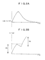
- Fig. 9A shows the curves showing the conditions that the voltage and current are changed from the dielectric breakdown to the state of retaining the arc discharge.
- the sealed gas such as mercury or xenon is ionized by the application high voltage, typically of 1000°C or more, to the electrodes of the discharge lamp to generate an electrically conductive gas.
- This phenomenon is called "dielectric breakdown".
- Subsequent continuous application of a voltage over several hundreds volt to the electrodes causes the collision of the electrons with the atoms in the ionized, electrically conductive gas, leading to the further progress of the ionization. This results in the retaining of the discharge (see arrow (12)).
- the electrons taking part in the ionization are those discharged from the atoms, as a result of the dielectric breakdown of the gas.
- the state that the discharge is continued is called "glow discharge".
- the voltage between the electrodes at which the discharge is generated is generally from approximately 90 to 120V, and the current run between these electrodes is not more than several hundreds mA.
- a lighting device comprising a resister so-called leakage resister capable of regulating the current at the time of shorting the load, and a switch mode lighting device utilizing semiconductor elements, and a lighting device which utilizes a starter for causing the dielectric breakdown of the sealed gas within the discharge lamp to cause the glow discharge and the arc discharge.
- the starter of the lighting device is composed of a direct current high voltage generating circuits, which arranged on the discharge lamp in parallel and, at the same time, diode connected between the main power circuit and the discharge lamp not so as to apply a high voltage to the direct current main power circuit for maintaining the arc discharge.
- the starter for the discharge lamp may be on which can generate a voltage of not less than 1000 V, which is required for the dielectric breakdown of the sealed gas, and which can supply a current enough for starting the arc discharge.
- the main power may be one which can supply a current and a voltage enough for maintaining the arc discharge as shown on the curve d of Fig. 9A.
- the output current and power characteristics of the starter should be those shown as the dot line b of Fig. 9A.
- the starter since it is required to generate a high voltage enough for the dielectric breakdown, the starter utilizes a transformer having a high boosting ratio. For this reason, the starter can only supply a faint current and, thus, the output voltage and current characteristics of the discharge lamp results in a double broken line b of Fig. 9A. Consequently, the dielectric breakdown of the sealed gas can be caused, but it becomes sometimes impossible to maintain the glow discharge state and to make transition transferred to the arc discharge.
- a device for lighting a discharge lamp in which a smoothing capacitor for rectification having a large capacity so that electric charge collected in the capacitor are instantly run through the discharged lamp at the time of starting the discharge, and by the virtue of the large amount of the electric current at this time, the state is shifted to the arc discharged state (see Japanese Patent No. 2705010 and Japanese Patent No. 2705018).
- the present invention has been made in order to solve the problems mentioned previously and an object of the present invention is to provide a device for lighting a discharge lamp which does not generate radio wave disorder according to rapid change in the electric current and voltage, which can reduce its weight and which is capable of suppressing the cause of sputtering electrodes as little as possible.
- Another object of the present invention is to provide a process for lighting a discharge lamp excelling in the working of re-lighting.
- a first aspect of the present invention concerns a device for lighting a discharge lamp comprising a rectifier, a switching circuit having a semiconductor element to be connected to said rectifier; a direct power supplying circuit having a rectifying circuit and filtering circuit each connected to said switching circuit; and a discharge lamp and a starter which are connected after said filtering circuit; said starter having a transformer and a smoothing capacitor for generating a high voltage; and said device having a circuit having a switching element and a resistance connected in series provided between the smoothing capacitor and said discharge lamp and further having a second capacitor connected parallel to said discharge lamp.
- said switching element supplies a voltage to said discharge lamp in such a manner that the voltage set until the conditions for causing the dielectric break down of the sealed gas of the discharge lamp are ready.
- said second capacitor has a capacitor smaller than that of said smoothing capacitor.
- a second aspect of the present invention concerns a device for lighting a discharge lamp comprising a switching circuit having a semiconductor, transformers connected one by one to said switching circuit, a rectifying circuit connected to said resisters, a filtering circuit connected to said rectifying circuit, a discharge lamp connected after the rectifying circuit and a starter for starting said discharge lamp; said transforners having a primary winding for supplying main current to a secondary winding and at the same time having second auxiliary windings, and supplying a direct voltage obtainable from a rectifying circuit connected to said second auxiliary windings to the main voltage supplying circuit via a starting switching circuit until the discharge lamp is stably lightened.
- said starter possesses a smoothing capacitor for generating a high voltage, and a circuit having a switching element and a resister connected in series, former capacitor is conductive at a voltage higher than a prescribed level, and said starter is connected to said discharge lamp in series.
- said starting switching circuit possesses a circuit for discriminating discharge, one end of which circuit is connected to a current-voltage detecting circuit and, at the same time, a working portion which decides "ON” or "OFF” of said starting switching circuit, according to the output from said circuit for discriminating discharge.
- a third aspect of the present invention concerns a process lighting a discharge lamp comprising: supplying to a discharge lamp, a high voltage for dielectric breakdown from a starter and, at same time, a high voltage for dielectric breakdown, which is lower than the former voltage, from an auxiliary winding provided on a transformer to cause dielectric breakdown to thereby cause a glow discharge between the electrodes of the discharge lamp, whereby a current runs between the electrode to stop the starter, and when the conditions of arc discharge are satisfied and the amount of the current becomes more than a prescribed set value, supplying a current from a main power circuit to the discharge lamp to lighten the discharge lamp, the process further comprising the following step: supplying, after stopping the starter, an additional high voltage for discharge from auxiliary winding to shit the glow discharge into the arc discharge, and then breaking the voltage therefrom.
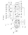
- Fig. 1 is a circuit diagram totally showing the device for a discharge lamp according to one embodiment of the present invention
- Fig. 2 is a graph showing the voltage-current characteristics of the switching element of the device for lighting a discharge lamp according to the present invention
- Fig. 3A is a graph showing the relationship between the lamp current and the time
- Fig. 3B is a graph showing the starting voltage of the switching element.
- a device A for lighting a discharge lamp is composed of a commercially available power source 101, a rectifying circuit 102 which is connected to the power source 101, a switching circuit 103 which is connected to the rectifying circuit 102, a circuit 104 for supplying direct power which is connected to the switching circuit 103, a device 114 for detecting a current and voltage, which is connected to the circuit 104, a discharge lamp 108 which is connected to the device 114 via a diode 107, a second capacitor 110 which is connected to the discharge lamp 108 in parallel, a starter 106 which is connected to the circuit 104 for supplying direct power, and a series connecting circuit 131 comprising switching element 130 and a resistance 109 which is connected between the starter 106 and the discharge lamp 108.
- the circuit 104 for supplying direct power is composed of a transformer 105, diodes 118b and 118a serving as a second rectifying circuit, which is connected to a secondary winding of the primary winding of the transformer 105, a chalk coil 119 which is connected to the output sides of the diodes 118b and 118a, a smoothing capacitor 120 (filtering circuit) which is connected to the chalk coil 119 in parallel.
- the starter 106 connects to the resistance 106a and a diode AC switch (DIAC) 106c in series and is composed of a capacitor 106b which connects the resistance 106a and the DIAC 106c in parallel, a transformer 106d for generating a high voltage provided downstream of the DIAC 106c, a diode 106e provided downstream of the transformer 106d for generating a high voltage, and a smoothing capacitor 106f which connects to the diode 106e in parallel.
- DIAC diode AC switch
- the winding ratio of the transformer 106d is set at a high value so as to be able to generate a voltage not less than twice the initial current-running of the switching element 130.
- the series-connecting circuit 131 which connects the starter 106 and the discharge lamp 108 in series, and is composed of, from the discharge lamp 108 side, a resister 109, and a switching element 130 connected downstream of the resister 109.
- a trigger element such as a spark gap or DIAC is used in the switching element 130.
- the electric power when being connected to the commercially available power source 101, the electric power is converted into a direct power through the rectifying circuit 102. Subsequently, the direct current is converted into a high frequency electric power through a filtering circuit 103, and then output from diodes 118b and 118a, which are the transformer 105 and a second rectifying circuit, respectively.
- a starter 106 gets powers from the diodes 118b and 118a, and generates a high frequency switching voltage by means of a relaxation oscillating circuit utilizing a trigger element to drive a transformer 106d having a high voltage rising ratio.
- the voltage output from the starter 106 is supplied to the discharge lamp 108 via the circuit 131 connecting the switching element 130 and the resister 109 in series.
- a high voltage from the starter 104 is never applied.
- the circuit 131 which possesses the resister 109 can be prevented from the generation of rapidly oscillating current, since momentary current running from the smoothing capacitor 106f toward the discharge lamp 108 can be suppressed.
- the second capacitor 110 connected to the discharge lamp 108 which tends to the situation where current is easily run, in parallel, can suppress the rapid change in voltage of the discharge lamp 108.
- the switching element 130 and the second smoothing capacitor are connected in series.
- the voltage for running the current to the switching element 130 again is a voltage that in addition to the voltage applied to the second capacitor 110, the voltage for initiating the running of the current to the switching element 130 is added (see Fig. 3B). Consequently, since the discharge lamp 108 is applied to a high voltage as high as the voltage applied to the second capacitor 110, the discharge lamp 108 easily brings about the dielectric breakdown, and there is a tendency to be shifted into the arc discharge.
- the discharge lamp 108 can easily be lightened again even if the temperature of the sealed gas in the discharge lamp 108 is not decreased enough.
- the charge which has been deposited on the smoothing capacitor 106f before the current is run to the switching element 130 is divided both into the smoothing capacitor 106f and the second capacitor 110.
- the value of the second capacitor 110 is small, the decrease in the voltage is small as such and, thus, the voltage of the second capacitor 110 is adjusted to the level close to that of the smoothing capacitor 120. For example, if the capacity of the second capacitor 110 is equal to that of the smoothing capacitor 120, the decrease in voltage become the value half the voltage before the decrease.
- the capacity of the second capacitor 110 is 1/10 that of the smoothing capacitor 120, the decrease in the voltage is as low as 1/10 the voltage before decreasing. Consequently, in the later case, much more high voltage can be applied to the discharge lamp 108 to ensure the dielectric breakdown.
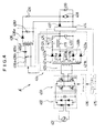
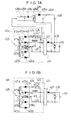
- Fig. 4 is a circuit diagram totally showing the device for a discharge lamp according to another embodiment of the present invention
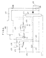
- Fig. 5 is a circuit diagram showing the main portion of the switching circuit of the present invention
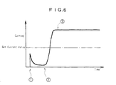
- Fig. 6 is a graph showing the change in current with the elapse of time and showing a set value of the current
- Fig. 7A and Fig. 7B each shows a circuit showing the current in the switching circuit of the present invention
- Fig. 8 shows a circuit diagram illustrating the main portion of another embodiment of the switching circuit used according to the present invention.
- the device A' for lighting a discharge lamp is composed of a power source 401 which is generally commercially available type, a rectifying circuit 402 connected to the power source 401, a switching circuit 403 connected to the rectifying circuit 402, a circuit 404 for being converted into direct power connected to the switching circuit 403, a detector 414 for detecting a current and a voltage connected to the converter circuit 404, a discharge lamp 408 connected to the detector 414 via a diode 407, a capacitor 410 connected to the discharge lamp 408 in parallel, a switching circuit 424 for starting provided on the circuit 404 for being converted into direct power, a starter 406 which works via the switching circuit 424 for starting, and a resister 409 provided between the starter 406 and the discharge lamp 408 in series.
- a power source 401 which is generally commercially available type
- a rectifying circuit 402 connected to the power source 401
- a switching circuit 403 connected to the rectifying circuit 402
- a circuit 404 for being converted into direct power connected to
- the signal detected from the detector 414 is transmitted to the switching circuit 406 via a circuit 415 for controlling a power and a driver circuit 416 which works by a signal from the circuit 415 for controlling a power.
- the switching circuit 404, a detector 414 for detecting a current and a voltage possesses a transformer 405, secondary windings 417a and 417b of the primary winding of the transformer 405, second auxiliary windings 421a and 421b of the secondary windings 417a and 417b, diodes 418a and 418b, and diodes 422a and 422b each provided on the secondary windings 417a and 417b and the second auxiliary windings 421a and 421b (to make a rectifying circuit), a switching circuit 424 for starting connected to the diodes 422a and 422b via a resister 423, a chalk coil 419 connected to the diodes 418a and 418b, and a smoothing capacitor 420 connected to the chalk coil 419 in parallel.
- the starter 406 is connected to a resister 406a and a DIAC 406c in series and, at the same time, is composed of a capacitor 406b connected to the resister 406a and the DIAC 406c in parallel, a transformer 406d provided downstream of the DIAC 406c, a diode 406e connected downstream of the transformer 406d, and a capacitor 406f connected to the diode 406e in parallel.
- the initial resistance becomes higher in the case of running a current and, thus, when the working for starting the discharge lamp is made, the voltage is then lowered to open switch portions 424a and 424b to thereby be stopped.
- the switching circuit 424 for starting is composed of a circuit 425 for discriminating a discharge, a transistor 427 provided on the output side of the circuit 425 for discriminating a discharge via a resistance, a relay coil 428 connected to the transistor 427, a power source 429 connected to the relay coil 428, one end of the power source 429 being grounded.
- a power source 426 is connected to the non-inversion input side of the comparator of the circuit 425 for discriminating a discharge, and the output terminal of the detector 414 for detecting a current and a voltage is connected to the inversion input side of the comparator of the circuit 425.
- a switch portion 424a Opposite to the relay coil 428 is provided a switch portion 424a, which controls open or close in communication with driving or stopping the relay coil 428.
- the circuit 425 for discriminating the a discharge state, i.e., whether it is in a glow discharge or an arc discharge to control the switch portion 424a will now be described.
- the power source generates a standard voltage for discriminating the a discharge state, i.e., whether it is in a glow discharge or an arc discharge.
- the circuit 425 discriminates the discharge state based on the difference of the voltage from the standard voltage to control the switch portion 424a.
- the standard voltage is calculated from the relational expression of current and voltage each for generating the dielectric breakdown (4) of the sealed gas within the discharge lamp 408, the glow discharge (5) and the arc discharge, and from the set value which has been set in each state (value of voltage calculated as current).
- the current in the glow discharge detected input from the detector has a small value (that is, higher than the standard voltage) and, thus the output voltage of the circuit 425 is high. Consequently, transistor 427 is turned on to start the relay coil 428 to close the switch portion 424a.
- the output voltage of the circuit 425 is low to turn the transistor 427 off. As a result, the current of the relay coil 428 is broken to open the switch portion 424a.
- the switching circuit 424 for starting works to supply a high voltage from the starter 406 to the discharge lamp 408 to generate a dielectric breakdown and, at the same time, to generate a glow discharge.
- the voltages at the sides of the second auxiliary windings 421a and 421b are in the state lower than the voltage at the starter 406 side.
- Running the current in the glow stage lowers the voltage of the starter 406 due to the high internal resistance whereby the starter 406 is substantially stopped. Consequently, unnecessary current does not run to the resistance 409, meaning the prevention of the loss due to heat of the direct resistance. For this reason, the heat loss generated in the resistance can be prevented.
- the voltage of the starter 406 when the voltage of the starter 406 is lowered, the total voltage from the second auxiliary windings 421a and 421b is in the state higher than the voltage of the starter 406 side.
- the voltage (a high voltage for discharge) is additionally supplied to the discharge lamp 408 from the second auxiliary windings 421a and 421b via the diodes 422a and 422b through the circuit separate from the starter 406. Due to the existence of the second the second auxiliary windings 421a and 421b, the voltages at the second auxiliary windings 421a and 421b sides are as high as approximately twice the voltage of the main power circuit, leading to reverse bias. In this case, the current from the secondary winding residing at the side of the main power circuit does not run. The current runs in the direction shown by the arrow in Fig. 7A.
- the discharge lamp 408 starts the discharge due to the arc discharge being shifted from the glow discharge, the voltage between the electrodes of the discharge lamp 408 is lowered to generate the current due to the arc discharge.
- the arc current causes the switching circuit 424 for starting to be in the open state by means of the detector 414 for detecting a current and voltage and the circuit 425 for discriminating discharge to break the supplying of the power from the second the second auxiliary windings 421a and 421b.
- the bias becomes in the normal state.
- the current is supplied from the secondary windings 417a and 417b to the discharge lamp 408 in the direction shown as the arrow. Thereafter, the discharge lamp 408 is lightened in the steady state by means of the direct power from the secondary windings 417a and 417b residing in the main power circuit.
- the switching circuit for starting may be constructed as shown in Fig. 8.
- the switching circuit 824 starting is composed of a circuit 825 for discriminating discharge, a transistor 827 provided on the output side of the circuit 825 for discriminating discharge via a resister, and a PNP transistor 824c serving as a switch portion connected to the transistor via the transistor 827.
- a power source 826 is connected to the non-inversion input side of the comparator of the circuit 425 for discriminating a discharge, and the output terminal of the detector 814 for detecting a current and a voltage is connected to the inversion input side of the comparator of the circuit 825.
- the transistor 827 becomes an on-state.
- the switch portion 824b is on state accordingly, corresponding to the state that the connecting point of the relay coil 428 is closed described above (see Fig. 5).
- the transistor 827 becomes an off-state accordingly.
- the base current of the PNP transistor 824c is broken to turn the switch portion 824b off, corresponding to the state that the connecting point of the relay coil 428 is opened described above (see Fig. 5).
- the circuit 825 for discriminating discharge has effects similar to those of the circuit 425 for discriminating discharge.
- a switching element 411 or 811 as shown as an imaginary line in Fig. 5 or Fig. 8 is connected to the resister 409 or 809 in series to make a series-connecting circuit, which is provided between the starter 406 or 806 and the discharge lamp 408 or 808.
- the switching element 411 or 811 is provided, the working of the starter 406 or 806 and the stopping of the switching element 411 or 811 are ensured when the voltage of the starter 406 or 408 is lowered. For this reason, the dielectric breakdown, the glow discharge and the shift into the arch discharge of the discharge lamp 408 or 808 can be ensured.
- the additional output voltage and additional output current from the second auxiliary windings 421a and 421b have the characteristics required for shifting the glow discharge state into the arc discharge state. For this reason, it is only required the second auxiliary windings 421a and 421b run a current only in an amount sufficient for initiating the arc discharge and, thus, the capacity thereof can be smaller than that of the secondary windings 417a and 417b (main current winding).
Landscapes
- Circuit Arrangements For Discharge Lamps (AREA)
Applications Claiming Priority (4)
| Application Number | Priority Date | Filing Date | Title |
|---|---|---|---|
| JP17874498A JP3438128B2 (ja) | 1998-06-25 | 1998-06-25 | 放電灯点灯装置 |
| JP17874498 | 1998-06-25 | ||
| JP17874598 | 1998-06-25 | ||
| JP17874598A JP3438129B2 (ja) | 1998-06-25 | 1998-06-25 | 放電灯点灯装置 |
Publications (3)
| Publication Number | Publication Date |
|---|---|
| EP0967843A2 true EP0967843A2 (de) | 1999-12-29 |
| EP0967843A3 EP0967843A3 (de) | 2001-07-11 |
| EP0967843B1 EP0967843B1 (de) | 2006-04-19 |
Family
ID=26498837
Family Applications (1)
| Application Number | Title | Priority Date | Filing Date |
|---|---|---|---|
| EP99304232A Expired - Lifetime EP0967843B1 (de) | 1998-06-25 | 1999-06-01 | Anordnung zum Betreiben einer Entladungslampe |
Country Status (3)
| Country | Link |
|---|---|
| US (1) | US6114815A (de) |
| EP (1) | EP0967843B1 (de) |
| DE (1) | DE69930897T2 (de) |
Cited By (2)
| Publication number | Priority date | Publication date | Assignee | Title |
|---|---|---|---|---|
| WO2006108406A1 (de) * | 2005-04-14 | 2006-10-19 | Patent-Treuhand-Gesellschaft für elektrische Glühlampen mbH | Vorrichtung zum betreiben oder zünden einer hochdruckentladungslampe, lampensockel und beleuchtungssystem mit einer derartigen vorrichtung sowie verfahren zum betreiben einer hochdruckentladungslampe |
| CN110673006A (zh) * | 2019-09-20 | 2020-01-10 | 广东华邦创科智能技术有限公司 | 一种在线式it系统直流射电绝缘检测装置 |
Families Citing this family (5)
| Publication number | Priority date | Publication date | Assignee | Title |
|---|---|---|---|---|
| WO2006004273A1 (en) * | 2004-04-16 | 2006-01-12 | Joongang Control Co., Ltd. | Electronic switch for voltage stabilization and power consumption minimization |
| KR200356541Y1 (ko) * | 2004-04-16 | 2004-07-15 | 중앙제어 주식회사 | 전원 안정화 및 소비전력 극소화를 위한 전자식 스위치 |
| CA2604456A1 (en) * | 2005-04-14 | 2006-10-19 | Patent-Treuhand-Gesellschaft Fuer Elektrische Gluehlampen Mbh | Starter auxiliary electrode starting device with an arc gap |
| DE102010029146A1 (de) * | 2010-05-20 | 2011-11-24 | Osram Gesellschaft mit beschränkter Haftung | Schaltungsanordnung zum Zünden von Hochdruckentladungslampen |
| JP2014027855A (ja) * | 2012-07-30 | 2014-02-06 | Funai Electric Co Ltd | 電源回路 |
Family Cites Families (13)
| Publication number | Priority date | Publication date | Assignee | Title |
|---|---|---|---|---|
| JPS6016080B2 (ja) * | 1980-08-20 | 1985-04-23 | ウシオ電機株式会社 | 直流放電灯点灯装置 |
| JPS63244589A (ja) * | 1987-03-31 | 1988-10-12 | ウシオ電機株式会社 | 放電灯点灯装置 |
| JPS63244590A (ja) * | 1987-03-31 | 1988-10-12 | ウシオ電機株式会社 | 放電灯点灯装置 |
| NL8701358A (nl) * | 1987-06-11 | 1989-01-02 | Philips Nv | Schakelinrichting. |
| JPH01159396A (ja) * | 1987-12-16 | 1989-06-22 | Hitachi Ltd | 部分めっき装置 |
| US5173643A (en) * | 1990-06-25 | 1992-12-22 | Lutron Electronics Co., Inc. | Circuit for dimming compact fluorescent lamps |
| DE9015674U1 (de) * | 1990-11-15 | 1992-03-12 | Patent-Treuhand-Gesellschaft für elektrische Glühlampen mbH, 8000 München | Getaktetes Schaltnetzteil für den Betrieb einer Entladungslampe |
| CA2103432A1 (en) * | 1992-12-11 | 1994-06-12 | Timothy A. Taubert | Versatile circuit topology for off line operation of a dc high intensity discharge lamp |
| JP3258758B2 (ja) * | 1993-04-12 | 2002-02-18 | 池田デンソー株式会社 | 放電灯点灯装置 |
| GB2277415B (en) * | 1993-04-23 | 1997-12-03 | Matsushita Electric Works Ltd | Discharge lamp lighting device |
| JP3329929B2 (ja) * | 1994-02-15 | 2002-09-30 | 松下電工株式会社 | 高圧放電灯点灯装置 |
| JP3521501B2 (ja) * | 1994-10-12 | 2004-04-19 | 株式会社デンソー | 高圧放電灯点灯装置 |
| JPH08229200A (ja) * | 1995-02-28 | 1996-09-10 | Maruhon:Kk | パチンコ遊技機用風車 |
-
1999
- 1999-06-01 DE DE69930897T patent/DE69930897T2/de not_active Expired - Fee Related
- 1999-06-01 EP EP99304232A patent/EP0967843B1/de not_active Expired - Lifetime
- 1999-06-25 US US09/344,364 patent/US6114815A/en not_active Expired - Lifetime
Cited By (3)
| Publication number | Priority date | Publication date | Assignee | Title |
|---|---|---|---|---|
| WO2006108406A1 (de) * | 2005-04-14 | 2006-10-19 | Patent-Treuhand-Gesellschaft für elektrische Glühlampen mbH | Vorrichtung zum betreiben oder zünden einer hochdruckentladungslampe, lampensockel und beleuchtungssystem mit einer derartigen vorrichtung sowie verfahren zum betreiben einer hochdruckentladungslampe |
| CN110673006A (zh) * | 2019-09-20 | 2020-01-10 | 广东华邦创科智能技术有限公司 | 一种在线式it系统直流射电绝缘检测装置 |
| CN110673006B (zh) * | 2019-09-20 | 2021-09-10 | 广东华邦创科智能技术有限公司 | 一种在线式it系统直流射电绝缘检测装置 |
Also Published As
| Publication number | Publication date |
|---|---|
| EP0967843A3 (de) | 2001-07-11 |
| EP0967843B1 (de) | 2006-04-19 |
| DE69930897D1 (de) | 2006-05-24 |
| DE69930897T2 (de) | 2006-11-23 |
| US6114815A (en) | 2000-09-05 |
Similar Documents
| Publication | Publication Date | Title |
|---|---|---|
| US5751120A (en) | DC operated electronic ballast for fluorescent light | |
| US6975077B2 (en) | High intensity discharge lamp ballast apparatus | |
| US6734641B2 (en) | Device for turning on light and illumination apparatus | |
| JPH07230884A (ja) | 高圧放電灯点灯装置 | |
| US6815908B2 (en) | Dimmable self-oscillating electronic ballast for fluorescent lamp | |
| KR100281373B1 (ko) | 고강도 방전 램프용 전자 밸러스트 | |
| US4550272A (en) | Operating circuit for electric discharge lamp | |
| US6114815A (en) | Device and process for lighting discharge lamp | |
| US6864642B2 (en) | Electronic ballast with DC output flyback converter | |
| CN1110230C (zh) | 电路装置 | |
| EP0671869B1 (de) | Vorschaltgerät für eine Lampe | |
| US6373199B1 (en) | Reducing stress on ignitor circuitry for gaseous discharge lamps | |
| JP2000348884A (ja) | 電極高圧放電ランプを始動および作動する方法および回路装置 | |
| US5994846A (en) | Buck converter switching scheme | |
| US4353011A (en) | Hot cathode discharge lamp lighting device | |
| US5369340A (en) | Driving scheme for a high intensity discharge ballast down converter | |
| JPH04342993A (ja) | 放電灯点灯装置 | |
| JP3438129B2 (ja) | 放電灯点灯装置 | |
| JP3438128B2 (ja) | 放電灯点灯装置 | |
| JP2590676B2 (ja) | 放電灯点灯装置 | |
| JP2001351790A (ja) | 放電灯点灯装置 | |
| JP2008108670A (ja) | 高圧放電灯点灯装置 | |
| JP2705018B2 (ja) | 放電ランプ点灯装置 | |
| JP2010055915A (ja) | 高圧放電灯点灯装置、光源装置及び高圧放電灯の始動方法 | |
| JPH0254900A (ja) | 放電灯点灯装置 |
Legal Events
| Date | Code | Title | Description |
|---|---|---|---|
| PUAI | Public reference made under article 153(3) epc to a published international application that has entered the european phase |
Free format text: ORIGINAL CODE: 0009012 |
|
| AK | Designated contracting states |
Kind code of ref document: A2 Designated state(s): DE FR GB IT |
|
| AX | Request for extension of the european patent |
Free format text: AL;LT;LV;MK;RO;SI |
|
| PUAL | Search report despatched |
Free format text: ORIGINAL CODE: 0009013 |
|
| AK | Designated contracting states |
Kind code of ref document: A3 Designated state(s): AT BE CH CY DE DK ES FI FR GB GR IE IT LI LU MC NL PT SE |
|
| AX | Request for extension of the european patent |
Free format text: AL;LT;LV;MK;RO;SI |
|
| RIC1 | Information provided on ipc code assigned before grant |
Free format text: 7H 05B 41/29 A, 7H 05B 41/38 B |
|
| 17P | Request for examination filed |
Effective date: 20010803 |
|
| AKX | Designation fees paid |
Free format text: DE FR GB IT |
|
| 17Q | First examination report despatched |
Effective date: 20020329 |
|
| GRAC | Information related to communication of intention to grant a patent modified |
Free format text: ORIGINAL CODE: EPIDOSCIGR1 |
|
| GRAP | Despatch of communication of intention to grant a patent |
Free format text: ORIGINAL CODE: EPIDOSNIGR1 |
|
| RIC1 | Information provided on ipc code assigned before grant |
Ipc: 7H 05B 41/38 B Ipc: 7H 05B 41/288 A |
|
| RTI1 | Title (correction) |
Free format text: DEVICE FOR LIGHTING DISCHARGE LAMP |
|
| GRAS | Grant fee paid |
Free format text: ORIGINAL CODE: EPIDOSNIGR3 |
|
| GRAA | (expected) grant |
Free format text: ORIGINAL CODE: 0009210 |
|
| AK | Designated contracting states |
Kind code of ref document: B1 Designated state(s): DE FR GB IT |
|
| PG25 | Lapsed in a contracting state [announced via postgrant information from national office to epo] |
Ref country code: IT Free format text: LAPSE BECAUSE OF FAILURE TO SUBMIT A TRANSLATION OF THE DESCRIPTION OR TO PAY THE FEE WITHIN THE PRESCRIBED TIME-LIMIT;WARNING: LAPSES OF ITALIAN PATENTS WITH EFFECTIVE DATE BEFORE 2007 MAY HAVE OCCURRED AT ANY TIME BEFORE 2007. THE CORRECT EFFECTIVE DATE MAY BE DIFFERENT FROM THE ONE RECORDED. Effective date: 20060419 |
|
| REG | Reference to a national code |
Ref country code: GB Ref legal event code: FG4D |
|
| REF | Corresponds to: |
Ref document number: 69930897 Country of ref document: DE Date of ref document: 20060524 Kind code of ref document: P |
|
| ET | Fr: translation filed | ||
| PLBE | No opposition filed within time limit |
Free format text: ORIGINAL CODE: 0009261 |
|
| STAA | Information on the status of an ep patent application or granted ep patent |
Free format text: STATUS: NO OPPOSITION FILED WITHIN TIME LIMIT |
|
| 26N | No opposition filed |
Effective date: 20070122 |
|
| PGFP | Annual fee paid to national office [announced via postgrant information from national office to epo] |
Ref country code: DE Payment date: 20080626 Year of fee payment: 10 |
|
| PGFP | Annual fee paid to national office [announced via postgrant information from national office to epo] |
Ref country code: FR Payment date: 20080625 Year of fee payment: 10 |
|
| PGFP | Annual fee paid to national office [announced via postgrant information from national office to epo] |
Ref country code: GB Payment date: 20080418 Year of fee payment: 10 |
|
| GBPC | Gb: european patent ceased through non-payment of renewal fee |
Effective date: 20090601 |
|
| REG | Reference to a national code |
Ref country code: FR Ref legal event code: ST Effective date: 20100226 |
|
| PG25 | Lapsed in a contracting state [announced via postgrant information from national office to epo] |
Ref country code: FR Free format text: LAPSE BECAUSE OF NON-PAYMENT OF DUE FEES Effective date: 20090630 |
|
| PG25 | Lapsed in a contracting state [announced via postgrant information from national office to epo] |
Ref country code: GB Free format text: LAPSE BECAUSE OF NON-PAYMENT OF DUE FEES Effective date: 20090601 |
|
| PG25 | Lapsed in a contracting state [announced via postgrant information from national office to epo] |
Ref country code: DE Free format text: LAPSE BECAUSE OF NON-PAYMENT OF DUE FEES Effective date: 20100101 |