EP0968101B1 - Lenkstockmodul mit radialem zusammenbau - Google Patents
Lenkstockmodul mit radialem zusammenbau Download PDFInfo
- Publication number
- EP0968101B1 EP0968101B1 EP98917036A EP98917036A EP0968101B1 EP 0968101 B1 EP0968101 B1 EP 0968101B1 EP 98917036 A EP98917036 A EP 98917036A EP 98917036 A EP98917036 A EP 98917036A EP 0968101 B1 EP0968101 B1 EP 0968101B1
- Authority
- EP
- European Patent Office
- Prior art keywords
- steering column
- switch
- support board
- locating device
- column assembly
- Prior art date
- Legal status (The legal status is an assumption and is not a legal conclusion. Google has not performed a legal analysis and makes no representation as to the accuracy of the status listed.)
- Expired - Lifetime
Links
- 230000008054 signal transmission Effects 0.000 claims description 7
- 230000000717 retained effect Effects 0.000 claims description 6
- 239000000463 material Substances 0.000 claims description 4
- 230000002787 reinforcement Effects 0.000 claims description 3
- 230000001939 inductive effect Effects 0.000 claims description 2
- 239000004020 conductor Substances 0.000 description 6
- 238000010168 coupling process Methods 0.000 description 6
- 238000005859 coupling reaction Methods 0.000 description 6
- 230000000694 effects Effects 0.000 description 6
- 230000008878 coupling Effects 0.000 description 5
- 238000009434 installation Methods 0.000 description 5
- 238000004519 manufacturing process Methods 0.000 description 5
- 238000000926 separation method Methods 0.000 description 5
- 210000002105 tongue Anatomy 0.000 description 5
- 238000001514 detection method Methods 0.000 description 3
- 230000002349 favourable effect Effects 0.000 description 3
- 230000001965 increasing effect Effects 0.000 description 3
- 230000033001 locomotion Effects 0.000 description 3
- 230000007547 defect Effects 0.000 description 2
- 230000000994 depressogenic effect Effects 0.000 description 2
- 230000007257 malfunction Effects 0.000 description 2
- 230000009347 mechanical transmission Effects 0.000 description 2
- 230000005855 radiation Effects 0.000 description 2
- 230000008439 repair process Effects 0.000 description 2
- FYYHWMGAXLPEAU-UHFFFAOYSA-N Magnesium Chemical compound [Mg] FYYHWMGAXLPEAU-UHFFFAOYSA-N 0.000 description 1
- 230000003213 activating effect Effects 0.000 description 1
- 239000004411 aluminium Substances 0.000 description 1
- 229910052782 aluminium Inorganic materials 0.000 description 1
- XAGFODPZIPBFFR-UHFFFAOYSA-N aluminium Chemical compound [Al] XAGFODPZIPBFFR-UHFFFAOYSA-N 0.000 description 1
- 230000000712 assembly Effects 0.000 description 1
- 238000000429 assembly Methods 0.000 description 1
- 238000005452 bending Methods 0.000 description 1
- 230000005540 biological transmission Effects 0.000 description 1
- 230000007797 corrosion Effects 0.000 description 1
- 238000005260 corrosion Methods 0.000 description 1
- 230000006378 damage Effects 0.000 description 1
- 238000010586 diagram Methods 0.000 description 1
- 125000000524 functional group Chemical group 0.000 description 1
- 230000006872 improvement Effects 0.000 description 1
- 230000000977 initiatory effect Effects 0.000 description 1
- 229910052749 magnesium Inorganic materials 0.000 description 1
- 239000011777 magnesium Substances 0.000 description 1
- 238000004137 mechanical activation Methods 0.000 description 1
- 229910052751 metal Inorganic materials 0.000 description 1
- 239000002184 metal Substances 0.000 description 1
- 229910001092 metal group alloy Inorganic materials 0.000 description 1
- 230000005693 optoelectronics Effects 0.000 description 1
- 230000002028 premature Effects 0.000 description 1
- 230000009467 reduction Effects 0.000 description 1
- 238000007493 shaping process Methods 0.000 description 1
- 239000007858 starting material Substances 0.000 description 1
- 230000008093 supporting effect Effects 0.000 description 1
- 230000001360 synchronised effect Effects 0.000 description 1
Images


Classifications
-
- B—PERFORMING OPERATIONS; TRANSPORTING
- B60—VEHICLES IN GENERAL
- B60R—VEHICLES, VEHICLE FITTINGS, OR VEHICLE PARTS, NOT OTHERWISE PROVIDED FOR
- B60R16/00—Electric or fluid circuits specially adapted for vehicles and not otherwise provided for; Arrangement of elements of electric or fluid circuits specially adapted for vehicles and not otherwise provided for
- B60R16/02—Electric or fluid circuits specially adapted for vehicles and not otherwise provided for; Arrangement of elements of electric or fluid circuits specially adapted for vehicles and not otherwise provided for electric constitutive elements
- B60R16/023—Electric or fluid circuits specially adapted for vehicles and not otherwise provided for; Arrangement of elements of electric or fluid circuits specially adapted for vehicles and not otherwise provided for electric constitutive elements for transmission of signals between vehicle parts or subsystems
- B60R16/027—Electric or fluid circuits specially adapted for vehicles and not otherwise provided for; Arrangement of elements of electric or fluid circuits specially adapted for vehicles and not otherwise provided for electric constitutive elements for transmission of signals between vehicle parts or subsystems between relatively movable parts of the vehicle, e.g. between steering wheel and column
-
- B—PERFORMING OPERATIONS; TRANSPORTING
- B60—VEHICLES IN GENERAL
- B60Q—ARRANGEMENT OF SIGNALLING OR LIGHTING DEVICES, THE MOUNTING OR SUPPORTING THEREOF OR CIRCUITS THEREFOR, FOR VEHICLES IN GENERAL
- B60Q1/00—Arrangement of optical signalling or lighting devices, the mounting or supporting thereof or circuits therefor
- B60Q1/02—Arrangement of optical signalling or lighting devices, the mounting or supporting thereof or circuits therefor the devices being primarily intended to illuminate the way ahead or to illuminate other areas of way or environments
- B60Q1/04—Arrangement of optical signalling or lighting devices, the mounting or supporting thereof or circuits therefor the devices being primarily intended to illuminate the way ahead or to illuminate other areas of way or environments the devices being headlights
- B60Q1/14—Arrangement of optical signalling or lighting devices, the mounting or supporting thereof or circuits therefor the devices being primarily intended to illuminate the way ahead or to illuminate other areas of way or environments the devices being headlights having dimming means
- B60Q1/1446—Arrangement of optical signalling or lighting devices, the mounting or supporting thereof or circuits therefor the devices being primarily intended to illuminate the way ahead or to illuminate other areas of way or environments the devices being headlights having dimming means controlled by mechanically actuated switches
- B60Q1/1453—Hand actuated switches
- B60Q1/1461—Multifunction switches for dimming headlights and controlling additional devices, e.g. for controlling direction indicating lights
-
- B—PERFORMING OPERATIONS; TRANSPORTING
- B60—VEHICLES IN GENERAL
- B60R—VEHICLES, VEHICLE FITTINGS, OR VEHICLE PARTS, NOT OTHERWISE PROVIDED FOR
- B60R25/00—Fittings or systems for preventing or indicating unauthorised use or theft of vehicles
-
- B—PERFORMING OPERATIONS; TRANSPORTING
- B60—VEHICLES IN GENERAL
- B60R—VEHICLES, VEHICLE FITTINGS, OR VEHICLE PARTS, NOT OTHERWISE PROVIDED FOR
- B60R25/00—Fittings or systems for preventing or indicating unauthorised use or theft of vehicles
- B60R25/01—Fittings or systems for preventing or indicating unauthorised use or theft of vehicles operating on vehicle systems or fittings, e.g. on doors, seats or windscreens
- B60R25/02—Fittings or systems for preventing or indicating unauthorised use or theft of vehicles operating on vehicle systems or fittings, e.g. on doors, seats or windscreens operating on the steering mechanism
- B60R25/021—Fittings or systems for preventing or indicating unauthorised use or theft of vehicles operating on vehicle systems or fittings, e.g. on doors, seats or windscreens operating on the steering mechanism restraining movement of the steering column or steering wheel hub, e.g. restraining means controlled by ignition switch
- B60R25/02105—Arrangement of the steering column thereof
-
- B—PERFORMING OPERATIONS; TRANSPORTING
- B60—VEHICLES IN GENERAL
- B60R—VEHICLES, VEHICLE FITTINGS, OR VEHICLE PARTS, NOT OTHERWISE PROVIDED FOR
- B60R25/00—Fittings or systems for preventing or indicating unauthorised use or theft of vehicles
- B60R25/01—Fittings or systems for preventing or indicating unauthorised use or theft of vehicles operating on vehicle systems or fittings, e.g. on doors, seats or windscreens
- B60R25/04—Fittings or systems for preventing or indicating unauthorised use or theft of vehicles operating on vehicle systems or fittings, e.g. on doors, seats or windscreens operating on the propulsion system, e.g. engine or drive motor
Definitions
- the invention concerns a steering column assembly for arranging in the area of a steering column in a motor vehicle, comprising a locating device, a centrally arranged support board and at least one steering column switch, whereby the locating device comprises a receptacle for the support board and at least one laterally-aligned receptacle for the steering column switch; and whereby the support board establishes the electrical connection between the connections of the steering column switch and the control devices of the vehicle allocated to the steering column switch; and whereby the control devices allocated to the steering column switch are at least in part arranged on the support board.
- a locating device is for example known from EP 0 763 447 A2 (disclosing an assembly according to the preamble of claim 1) and the EP 0 929 415 A published after the filing date of the present patent (an Article 54(3) document).
- Switches arranged on a steering column assembly are used to operate and control various functions of the vehicle. Such functions can for example be switching the vehicle lights on and'off, initiating the turn signals or the windscreen wiper device, operating an automatic cruise control etc.
- the intention is to allow operation and control of as many functions of a vehicle as possible in close proximity to the steering wheel. Such an arrangement ensures that the driver can reach the controls without having to take whichever hand is necessary for operating the control away from the steering wheel region.
- EP 0 763 447 A2 shows a steering column lever with a locating device attachable to the steering column of a motor vehicle, with two laterally-aligned seats for two steering column switches to which a centrally arranged support board is allocated.
- This support board on the one hand establishes electrical connections between the connections of the steering column switch and the vehicle's control devices which are allocated to the steering column switch, whereby on the other hand the control devices allocated to the steering column switch are at least partly arranged on the support board.
- the electrical connection between the connections of the steering column switch and the support board takes place via plugs which can be plugged into the support board; these plugs are connected via cables to the contacts of the steering column switches.
- the support board is essentially configured in a circular shape; it is positioned into the respective receptacle of the locating device in the direction of the axis of the steering column.
- a further embodiment of a steering column assembly is known from DE 44 28 883 C1.
- This steering column assembly too comprises a locating device, a centrally arranged support board and two steering column switches.
- the support board is inserted as a ring-shaped component into a receptacle formed in the front of the locating device and aligned coaxially to the longitudinal axis of the steering column assembly.
- the steering column switches with electrical control elements form a firmly interconnected modular unit.
- the support board comprises press contacts which are laterally formed to it; by way of the said press contacts the contact surfaces of the electrical connections of the respective modular unit comprising steering column switch and switches, can be connected to the strip conductors of the support board.
- the strip conductors of the support board are connected to plug-in contacts fixed to the support board which, with the support board plugged in, are located in a respective plug-in connector. From the plug-in connector, a loom of cables leads to the respective control devices.
- the support board supports a sensor device by means of which the steering angle of the steering wheel borne by the steering column can be determined.
- a signal transmission device configured as a so-called helix cable cassette is connected via the support board with the control wires allocated to it.
- the known designs for a steering column assembly make it possible in a modular configuration to install various components in the steering-column region in a simple way.
- the individual components can be attached to the locating device in a confined space, as a functionally pre-tested unit.
- the installation effort is minimal in the case of the known device.
- a problem with the known design of a steering column assembly is the fact that should exchange of the support board become necessary due to a defect, it is necessary to remove the steering wheel and further components, in order to gain access to the support board.
- the support board for example in the device known from DE 44 28 883 C1 is merely configured as a simple lead-type connection between the switches connected to the steering column levers and the control elements which are positioned away from the steering column. For example, by way of these control elements vehicle lights are switched on or off, turn signal indicators are operated, the windscreen wiper device is operated at various speeds or automatic cruise control is activated.
- the object derived and shown above is met in that the receptacle for the support board is oriented in a radial direction, such that the support board can be connected to the locating device from a radial direction, the steering column switch is disconnectably connectable with the locating device, the steering column switch comprises a control, the control depending on its manually selectable position, by way of control means acts upon at least one switch element causing signal transmission, the switch element is arranged on the support board and the control means is a raised part shaped to the control.
- the support board is not only configured as a simple electrical connection between the switches of a steering column lever and a loom of cables, but it accommodates and connects the electronic control elements with the respective switches which are required to initiate and operate certain functions of the vehicle.
- the support board can be a fully-functional electronic printed circuit board.
- the control means arranged separately from the central support board provides the desired electrical function directly via the switch elements controlled by the respective controls. This considerably simplifies production because now only a single printed circuit board needs to be provided. This configuration results in an advantageous separation of mechanically and electrically operated components of the steering column assembly. In this, a spatial de-coupling of mechanical elements on the one hand, and electrical functional elements on the other hand takes place insofar as all electrical functions are concentrated on the support board, while the mechanical control means are arranged in the region of the steering column switches, independent of the support board.
- a steering column assembly comprises an assembly made of purely mechanical components and an assembly of electrical components which are allocated to a support board. Both assemblies represent individual design units. This makes it possible to install the mechanical elements of the steering column separately from its electrical elements and accordingly, to replace them independent from each other in case of a malfunction.
- the switch element constituting the essential electrical part of the switch can be preassembled on the support board; due to the modular design of the support board, it can be fixed on a group of components and be connected to an also fixed cabling of the group of components; and in the case of malfunction is easy to deinstall.
- the mechanical part which essentially comprises the control and the control means
- both installation of the steering column switches or the support board, as well as their replacement, are significantly simplified when compared with known designs of a steering column assembly.
- a form of the control means which is particularly simple and cost-effective in it realisation, used for mechanical transmission of the switch signal, is according to the present invention characterised in that the control means is configured as a raised part shaped to the control.
- the control elements are arranged in close proximity to the switches activating their function. In this way, cabling of the vehicle in the steering wheel region can be considerably simplified. Since in the case of the steering column assembly according to the invention, at the same time a receptacle is envisaged which makes it possible to plug the support board (which is equipped with control elements accordingly) into the locating device radially from a lateral direction, the support board can be installed and deinstalled very simply and in a short time. Therefore, in the case of the locating device according to the invention, the support board can also comprise service-intensive components whose unimpeded access must be ensured.
- the support board is U-shaped.
- the U-shape allows direct contact of all switches attached to the locating device.
- the support board can be inserted into a slot provided in the locating device, or if it can be put on the locating device, then the locating device can be laterally slid into the slot of the locating device in the sense of a modular unit. This further facilitates exchange of the support board in the case of repair.
- the locating device comprises a lock receptacle for a cylinder lock switch and that the electrical connection between the connections of the cylinder lock switch and the control devices allocated to the cylinder lock switch of the vehicle is maintained by way of the support board.
- the locating device forms a central supporting unit to which all essential elements necessary for operating the vehicle are attached.
- an additional lock receptacle is envisaged on the locating device, but it is equally advantageous if the locating device comprises a receptacle for the detection and control unit of a drive-away security device or an immobiliser. It can also accommodate a signal transmission device for an airbag which is arranged in the steering wheel borne by the steering column.
- control devices allocated to the cylinder lock switch are at least in part arranged on the support board.
- a further advantageous embodiment of the modular support board is achieved in that the cylinder lock switch is disconnectably connected with the locating device; in that the cylinder lock switch comprise a control; in that the control, depending on its manually selectable position, by way of control means acts upon at least one switch element causing signal transmission; and in that the switch element is arranged on the support board.
- This embodiment of the invention is characterised in that all components necessary for electronic or electrical functions of the steering column assembly are now arranged on a single support board.
- This support board represents the central control unit and comprises both the strip conductors required for electrical signal transmission and all necessary electronic components such as the control device and the switching elements. In contrast to the state of the art according to DE 44 28 883 C1, no further printed circuit boards are necessary. Transmission of the switch signal generated as a result of moving the position of the control, from the mechanical part of the switch to the switch element, can take place in a mechanical, photoelectrical, inductive, capacitive or magnetic way.
- the support board carry microswitches functioning as mechanical-electrical switch elements by means of which the mechanical activation of the switch is transformed into an electrical signal.
- the support board can also accommodate further transducers, for example optoelectronic transducers.
- the steering column switch is connected, by way of a connective element, to a receptacle for the steering column switch of the locating device, and the control of the steering column switch is retained at the connective element.
- the particular effect consists of a coupling being enabled between the functions of the steering column switch with the electrical or electronic control means housed on the support board, whereby quasi an "electronic steering column switch" can be realised.
- spatial decoupling between mechanical elements on the one hand and electrical functional elements on the other hand takes place to the effect that all electrical functions are concentrated on the support board, while the control means are located outside the said board, in the region of the steering column switch or components interacting with it.
- the elements connected to a connective element of the steering column switch, for connection to a receptacle for the steering column switch of the locating device should be made from the same material as the connective element.
- a further advantageous embodiment of the invention in view of resistance to wear and ease of installation, is characterised in that the connective element is a housing which clicks into the receptacle of the locating device.
- a preferred embodiment consists of the control means being configured as an axially-movable pin.
- the control means By means of such pins a swivelling motion can easily be converted into a purely axially directed movement.
- This makes it possible while maintaining a compact design to select a spatial allocation of a swivellably retained control and a switch element in which the switch element is positioned in a plane normally arranged to the swivelling axis of the control.
- the control means is a rotatably-held cam.
- the cylinder lock switch is connected with a lock receptacle of the locating device by way of a connective element, with the cylinder lock switch comprising a lock cylinder as a control.
- ignition lock and locating device form an integral unit, thus significantly simplifying both production and pre-assembly and assembly of the steering column assembly.
- all functions which are traditionally assumed by the locating device can be combined with the function of the cylinder lock switch.
- the particular effect consists in a coupling of the cylinder lock function with the electrical or electronic control means accommodated on the support board, whereby quasi an "electronic ignition lock" can be realised.
- control devices allocated to the steering column switch and/or the cylinder lock switch are at least partly arranged on the support board which is configured as a printed circuit board, and that the control devices, depending on the switch condition of the switch element, are controllable.
- the configuration of the support board as a printed circuit board can be used to bring the required electrical connection in a space-efficient and safe way close to the switch element. It is particularly favourable if electronic control circuits are arranged on the support board which is configured as a printed circuit board, with the said control circuits controlling the equipment of the motor vehicle, depending on the switch condition of the switch element.
- Such an embodiment of the support board makes it possible to locate the control elements which depend on the switch condition of the switch element in a space-efficient way in close proximity to the switch element. In this way expensive cabling can be dispensed with.
- the arrangement of switching elements and control elements on a common printed circuit board offers the possibility of creating a central switch unit and control unit of the vehicle, in the region of the steering column, in the location where for reasons of optimal ergonomics, all manually operated control devices should be arranged in close proximity to the steering wheel.
- the locating device according to the invention is made from a plastic material.
- the wall of the lock receptacle can, at least in sections, be reinforced by reinforcement elements embedded in the plastic.
- reinforcement elements should be made of metal.
- the locating device is made from a light-metal alloy which contains in particular magnesium and/or aluminium.
- a preferred embodiment of the invention in view of ease of installation and protection of the support board is characterised in that the support board is accommodated by a housing.
- a further reduction of the individual components present in the region of the steering wheel can be achieved in that sections of the outer walls of the locating device form the cover of the steering column which is visible from the outside.
- a preferred embodiment of the steering column assembly according to the invention provides for a turning angle sensor for registering the steering angle to be provided.
- the electronic elements of the said sensor are also arranged on the support board. In this way, a further function can be realised, namely the coupling of vehicle functions depending on the turning angle of the steering wheel.
- the support board accommodates a sensor for registering the torque acting upon the steering column, then there is an option of increasing the comfort by coupling it with a power steering function.
- a further design possibility in the sense of the invention consists of the support board accommodating a receiver device for an HF radio remote control.
- the area behind the steering wheel is eminently suitable for this because in this location, due to the size of the window areas, HF radiation can penetrate favourably and largely without any disturbance. Thus it is not necessary to provide another place for the HF receiver in the region of the control panel.
- the steering column 1 shown in Fig. 1 comprises a central locating device 2 which can be placed upon a jacket tube (not shown) of a steering column (also not shown). To this effect, a central aperture is shaped into the locating device 2, the diameter of which corresponds with the exterior diameter of the jacket tube (not shown).
- a first radially-aligned receptacle 4 is provided for a first steering column switch 3.
- a first steering column switch 3 In the region of a lateral surface of receptacle 4, in a flexible tongue 5, shaped to a lateral margin of receptacle 4, there are two click-lock apertures 6, 7.
- a second receptacle 8 for a second steering column lever 9.
- receptacle 8 in the region of its lateral surface comprises a flexible tongue 18 into which click-lock apertures 10, 11 have been formed.
- a slot-receptacle 13 is provided in order to attach a U-shaped support board 12 configured as an electronics printed circuit board to the locating device 2.
- the support board 12 is placed in a positive-locking way into a housing comprising two housing halves 14, 15, the U-shape of which corresponds to the U-shape of the support board 12.
- the support board 12 is inserted with the surrounding housing 14, 15 from radial direction into the slot receptacle 13.
- the support board 12 is positioned into the housing halves 14, 15 surrounding it, in a plane normally positioned along the longitudinal axis L of the locating device 2.
- microswitches 16, 17 On the side facing the housing half 14 of the support board 12, which in the condition where the support board 12 is attached to the locating device 2, is allocated to the housings 22, 23 of the steering column switches 3, 9, there are microswitches 16, 17 (shown by dotted lines). These microswitches 16, 17 can be operated by way of suitable control means of the steering column switches 3, 9.
- the steering column switches 3, 9 themselves do not have their own elements establishing an electrical connection. They only comprise the mechanical components necessary to activate the microswitches 16, 17.
- the steering column switches 3, 9 and the respective microswitches 16, 17 allocated to them jointly constitute a functional steering column switch in which constructional separation of mechanical and electrical parts is realised. This constructional separation leads to significant simplification in installing and deinstalling the steering column switch in the case of repair or similar.
- the microswitches 16, 17 are connected with the electronic components arranged on the support board 12, including control devices 19.
- control devices 19 For example the vehicle's lights, turn signal indicator, windscreen wiper device etc. are controlled depending on the swivel position of the steering column switch 3 or 9.
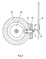
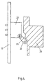
- the steering column switch 3, 9 is swivelled to such an extent that a control means shaped to it, for example a pin or cam, contacts a feeler 20 of a microswitch 21 (compare Fig. 2). If the feeler 20 of the microswitch 21 is depressed, depending on the function of the respective microswitch 21, an electrical connection is established or separated.
- a control means shaped to it for example a pin or cam
- the housing 22 or 23 of the steering column switch 3 or 9 can be inserted into the receptacles 4, 8. Laterally arranged guide means ensure that they can be inserted into the respective receptacle 4, 8 only in a particular position.
- the cover wall 24 allocated to the tongues 5 or 18 of the housings 22, 23 comprises click-stop protrusions 25 (compare Fig. 2). Where the housings 22 or 23 are inserted into the receptacles 4, 8, the said click-stop protrusions 25 interact with the respective click-stop apertures 6, 7 or 10, 11, in such a way that the steering column switches 3, 9 are securely retained to the locating device 2.
- the connection between the tongues 5, 18 and the click stops of the housings 22, 23 can be undone by bending back the respective tongues 5, 18.
- one control lever 27 each is swivellably retained on a swivel axis 26.
- the swivel axis 26 is arranged in the region of the wall 28 which, if the housing 22 or 23 is inserted into the receptacle 4 or 8, is facing outward.
- the wall 28 comprises a window through which the respective control lever 27 leads out of the housing 22, 23.
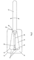
- the control lever 27 comprises an extension 29 protruding into the respective housing 22, 23.
- a wheel 30 is hinged in such a way that its turning axis is normally aligned to the longitudinal axis of the respective control lever 27.
- the wheel 30 movably arranged in longitudinal direction of the control lever 27 and by means of the force of an elastic element (not shown), is pushed towards an arc-shaped marginal section 32 comprising three click stops 31 spaced apart in regular angular spacing, of a recess 34 in a closed lateral wall 33 of the housing 22, 23.
- the click stops 31 define three switch positions for the respective control lever 27 of the steering column switches 3, 9.
- the surface of the extension 29 facing away from the first cover wall 24, in the region of its free end, comprises a step-shaped raised part 35 (compare Figs. 4 and 5) whose bevelled surfaces drop towards the elongated sides of the extension 29.
- the second cover wall of the housings 22 or 23 comprises a window the size of which corresponds to at least the area covered by the raised part 35 during a full sweep of the control lever 27, 29.
- the switch elements configured as microswitches 16, 17 on the side of the support board 12 which in a condition fixed to the locating device 2 is allocated to the housings 22, 23 (Fig. 2) are arranged in angular spacings corresponding to the angular spacings between the click stops 31. If the support board 12 embedded in the housing halves 14, 15 is inserted into the slot-receptacle 13, and the steering column switches 3, 9 are inserted into the receptacles 4 or 8 in the locating device 2, the housing 22 or 23 covers the window 36, 37 allocated to the respective steering column lever 3, 9 of the respective housing half 14, so that the microswitches 16, 17 positioned in these windows are effectively protected from dirt.
- microswitches 16, 17 are connected by way of strip conductors (not shown in detail) of the support board 12, with control devices 19 also arranged on the support board 12.
- control lever 27 is swivelled until the wheel 30 reaches the position, determined by one of the click stops 31, which corresponds to the desired function.
- the feeler 20 of the microswitch 21 allocated to this position is depressed by the raised part 35 of the lever extension 29.
- an electrical connection is established or separated in this way, depending on the function of the respective microswitch 21.
- the locating device 2 comprises an extension section 38 aligned coaxially to its longitudinal axis L.
- a lock receptacle 39 is shaped to the extension section 38.
- This lock receptacle 39 retains a lock cylinder 40 by means of a two-piece retainer 41.
- the lock cylinder 40 can be turned by means of a key 42 around a rotation axis X, shown in dashes in Fig. 1.
- the extension section 38 of the locating device 2 comprises an aperture 43 arranged coaxially to the aperture of the locating device 2.
- the steering shaft (not shown) of the steering column (also not shown) leads through the said aperture 43. With the key 42 removed and in the respective steering position, the steering shaft (not shown) can be locked in the traditional way by means of a wedge 44.
- the microswitches 46 are also connected to control devices (not shown) arranged on the support board 12. For example the starter motor (not shown) of the vehicle is controlled by the said control devices.
- the microswitches 46 constitute the electrical part of a cylinder lock switch 47 (compare Fig. 2) which can be activated by turning the lock cylinder 40 acting as a control.
- Cams 48 arranged with the lock cylinder 40 on the rotation axis of the lock cylinder 40 in various angular positions are provided to transmit the switching motion to the microswitches 46.
- Located on these cams 48 are the ends of pins 49 which are guided into the apertures 50 of the lock receptacle 39. In this, the apertures 50 are positioned in such a way that the other end of the respective pin 49 is in contact with the feeler 51 of the respective microswitch 46.
- the pins 49 are pushed out of the cam 48 allocated to each of them and push against the feeler 51 of the respective microswitch 46. Subsequently the said microswitch establishes an electrical connection or else it separates it.
- a receptacle 52 for a detection and control unit 53 of a drive-away security device (not shown) or an immobiliser For example, the detection and control unit 53 excites a transponder borne by the key 42 and depending on the signal received, for starting the vehicle, removes the drive-away lock.
- the electronic components required to carry out this function are also arranged on the support board 12.
- Coupling with a high-frequency radio remote-control of a vehicle can also take place via the centrally arranged electrical control unit, in that the receiver for the HF remote control is also accommodated on the support board 12. This is advantageous because the region below the steering wheel is preferably accessible for HF radiation from outside.
Landscapes
- Engineering & Computer Science (AREA)
- Mechanical Engineering (AREA)
- Steering Controls (AREA)
- Lock And Its Accessories (AREA)
- Switches With Compound Operations (AREA)
Claims (19)
- Lenksäulenbausatz (1) zur Anordnung im Bereich einer Lenksäule in einem Kraftfahrzeug,dadurch gekennzeichnet, dass:umfassend eine Haltevorrichtung (2);eine zentral angeordnete Trägerplatte (12); undzumindest einen Lenksäulenschalter (3, 9);wobei die Haltevorrichtung (2) eine Aufnahme (13) für die Trägerplatte (12) und zumindest eine seitlich ausgerichtete Aufnahme (4, 8) für den Lenksäulenschalter (3, 9) aufweist;die Trägerplatte (12) die elektrische Verbindung zwischen den Verbindungen des Lenksäulenschalters (3, 9) und den Steuervorrichtungen (19) des Fahrzeuges, welche dem Lenksäulenschalter (3, 9) zugeordnet sind, herstellt;die Steuervorrichtungen (19), die dem Lenksäulenschalter (3, 9) zugeordnet sind, zumindest teilweise auf der Trägerplatte (12) angeordnet sind;die Aufnahme (13) für die Trägerplatte (12) in einer radialen Richtung ausgerichtet ist, so dass die Trägerplatte (12) mit der Haltevorrichtung (2) aus einer radialen Richtung verbunden werden kann;der Lenksäulenschalter (3, 9) lösbar mit der Haltevorrichtung (2) verbindbar ist;der Lenksäulenschalter (3, 9) eine Steuerung (27, 29) umfasst;die Steuerung (27, 29) in Abhängigkeit von ihrer manuell wählbaren Position mit Hilfe von Steuermitteln auf zumindest ein Schalterelement (16, 17, 21) wirkt, das eine Signalübertragung hervorruft;das Schalterelement (16, 17, 21) auf der Trägerplatte (12) angeordnet ist; unddas Steuermittel ein erhöhter Teil (35) ist, der an die Steuerung (27, 29) angeformt ist.
- Lenksäulenbausatz (1) gemäß Anspruch 1, dadurch gekennzeichnet, dass die Trägerplatte (12) eine U-Form aufweist.
- Lenksäulenbausatz (1) gemäß Anspruch 1 oder 2, dadurch gekennzeichnet, dass die Trägerplatte (12) in einen Schlitz eingefügt werden kann, der in der Haltevorrichtung (2) bereitgestellt wird, oder auf die Haltevorrichtung (2) positioniert werden kann.
- Lenksäulenbausatz (1) gemäß einem der Ansprüche 1 bis 3, dadurch gekennzeichnet, dass die Haltevorrichtung (2) eine Schloss-Aufnahme (39) für einen Zylinderschlossschalter (47) umfasst, und dass die elektrische Verbindung zwischen den Verbindungen des Zylinderschlossschalters (47) und den Steuervorrichtungen (19) des Fahrzeuges, die dem Zylinderschlossschalter (47) zugeordnet sind, durch die Trägerplatte (12) hergestellt wird.
- Lenksäulenbausatz (1) gemäß Anspruch 4, dadurch gekennzeichnet, dass die Steuervorrichtungen (19), die dem Zylinderschlossschalter (47) zugeordnet sind, zumindest teilweise auf der Trägerplatte (12) angeordnet sind.
- Lenksäulenbausatz (1) gemäß einem der Ansprüche 1 bis 5, dadurch gekennzeichnet, dass der Zylinderschlossschalter (47) abschliessbar mit der Haltevorrichtung (2) verbindbar ist;der Zylinderschlossschalter eine Steuerung (40) umfasst;die Steuerung (40) in Abhängigkeit von ihrer manuell wählbaren Position mit Hilfe von Steuermitteln (48, 49) auf zumindest ein Schalterelement (46) wirkt, das eine Signalübertragung auslöst; unddas Schalterelement (46) auf der Trägerplatte (12) angeordnet ist.
- Lenksäulenbausatz (1) gemäß einem der Ansprüche 1 bis 6, dadurch gekennzeichnet, dass das Schalterelement (16, 17, 21, 46) auf mechanische, photoelektrische, induktive, kapazitive oder magnetische Weise bedient werden kann.
- Lenksäulenbausatz (1) gemäß einem der Ansprüche 1 bis 6, dadurch gekennzeichnet, dass das Schalterelement (16, 17, 21, 46) als Mikroschalter konfiguriert ist.
- Lenksäulenbausatz (1) gemäß einem der Ansprüche 1 bis 8, dadurch gekennzeichnet, dass der Lenksäulenschalter (3, 9) mit einer Aufnahme (4, 8) für den Lenksäulenschalter der Haltevorrichtung (2) über ein Verbindungselement (22, 23) verbunden ist, und die Steuerung (27, 29) am Verbindungselement zurückgehalten wird.
- Lenksäulenbausatz (1) gemäß Anspruch 9, dadurch gekennzeichnet, dass die Steuermittel mit dem Verbindungselement (22, 23) verbunden sind.
- Lenksäulenbausatz (1) gemäß Anspruch 9 oder 10, dadurch gekennzeichnet, dass die Elemente, die mit dem Verbindungselement (22, 23) verbunden sind, aus demselben Material wie das Verbindungselement (22, 23) bestehen.
- Lenksäulenbausatz (1) gemäß einem der Ansprüche 9 bis 11, dadurch gekennzeichnet, dass das Verbindungselement ein Gehäuse (22, 23) ist, das sich in die Aufnahme der Haltevorrichtung (2) klickt.
- Lenksäulenbausatz (1) gemäß einem der Ansprüche 1 bis 12, dadurch gekennzeichnet, dass die Steuerung (27, 29) in einer gelenkigen, linear beweglichen oder drehbaren Weise zurückgehalten wird.
- Lenksäulenbausatz (1) gemäß einem der Ansprüche 6 bis 13, dadurch gekennzeichnet, dass der Zylinderschlossschalter (47) mit einer Schloss-Aufnahme (39) der Haltevorrichtung (2) über ein Verbindungselement (41) verbunden ist, und der Zylinderschlossschalter (47) einen Schlosszylinder (40) als Steuerung umfasst.
- Lenksäulenbausatz (1) gemäß Anspruch 14, dadurch gekennzeichnet, dass das Steuermittel durch zumindest eine Nocke (48) gebildet wird, das auf der Drehachse des Schlosszylinders (40) angeordnet ist, und die Nocke (48) mit einem Schalterelement (46) interagiert, das auf der Trägerplatte (12) angeordnet ist.
- Lenksäulenbausatz (1) gemäß einem der Ansprüche 6 bis 15, dadurch gekennzeichnet, dass die Steuervorrichtungen, die dem Lenksäulenschalter (3, 9) und/oder dem Zylinderschlossschalter (47) zugeordnet sind, zumindest teilweise auf der Trägerplatte (12) angeordnet sind, die vorzugsweise als Leiterplatte konfiguriert ist, und die Steuervorrichtungen (19) in Abhängigkeit vom Schaltzustand des Schalterelementes (16, 17, 21, 46) steuerbar sind.
- Lenksäulenbausatz gemäß einem der Ansprüche 1 bis 16, dadurch gekennzeichnet, dass die Haltevorrichtung (2) aus einem Plastikmaterial hergestellt wird.
- Lenksäulenbausatz gemäß Anspruch 17, dadurch gekennzeichnet, dass die Wand der Schloss-Aufnahme (39) zumindest in Abschnitten durch Verstärkungselemente verstärkt wird, die im Plastik eingebettet sind.
- Lenksäulenbausatz gemäß einem der Ansprüche 1 bis 18, dadurch gekennzeichnet, dass Abschnitte der Außenwände der Haltevorrichtung (2) die Abdeckung der Lenksäule bilden, welche von außen sichtbar ist.
Applications Claiming Priority (9)
| Application Number | Priority Date | Filing Date | Title |
|---|---|---|---|
| DE19711566 | 1997-03-20 | ||
| DE19711567 | 1997-03-20 | ||
| DE19711566 | 1997-03-20 | ||
| DE19711560 | 1997-03-20 | ||
| DE19711561 | 1997-03-20 | ||
| DE1997111561 DE19711561C2 (de) | 1997-03-20 | 1997-03-20 | An einer Lenksäule eines Kraftfahrzeugs befestigbare Haltevorrichtung |
| DE1997111560 DE19711560C2 (de) | 1997-03-20 | 1997-03-20 | Im Bereich der Lenksäule eines Fahrzeuges angeordneter Schalter |
| DE19711567 | 1998-03-20 | ||
| PCT/EP1998/001649 WO1998042540A1 (de) | 1997-03-20 | 1998-03-20 | Steering column assembly |
Publications (2)
| Publication Number | Publication Date |
|---|---|
| EP0968101A1 EP0968101A1 (de) | 2000-01-05 |
| EP0968101B1 true EP0968101B1 (de) | 2001-10-31 |
Family
ID=27438576
Family Applications (2)
| Application Number | Title | Priority Date | Filing Date |
|---|---|---|---|
| EP98917036A Expired - Lifetime EP0968101B1 (de) | 1997-03-20 | 1998-03-20 | Lenkstockmodul mit radialem zusammenbau |
| EP98917037A Expired - Lifetime EP0968102B1 (de) | 1997-03-20 | 1998-03-20 | Lenkstockmodul mit zentraler elektrischer steuerungseinheit und nach radialem zusammenbau |
Family Applications After (1)
| Application Number | Title | Priority Date | Filing Date |
|---|---|---|---|
| EP98917037A Expired - Lifetime EP0968102B1 (de) | 1997-03-20 | 1998-03-20 | Lenkstockmodul mit zentraler elektrischer steuerungseinheit und nach radialem zusammenbau |
Country Status (5)
| Country | Link |
|---|---|
| US (1) | US6225582B1 (de) |
| EP (2) | EP0968101B1 (de) |
| AT (2) | ATE207829T1 (de) |
| DE (2) | DE69821743T2 (de) |
| WO (2) | WO1998042541A1 (de) |
Families Citing this family (18)
| Publication number | Priority date | Publication date | Assignee | Title |
|---|---|---|---|---|
| FR2765449B1 (fr) * | 1997-06-27 | 2005-05-27 | Valeo Electronique | Ensemble de commutation de haut de colonne de direction de vehicule automobile et procede de fabrication d'un tel ensemble |
| WO2001064484A1 (en) * | 2000-02-28 | 2001-09-07 | Delphi Technologies, Inc. | Column electronics control assembly |
| DE10017591A1 (de) * | 2000-04-08 | 2001-10-18 | Kostal Leopold Gmbh & Co Kg | Einrichtung zum Sperren der Drehbarkeit einer Lenkspindel eines Kraftfahrzeuges |
| DE10025651C2 (de) | 2000-05-24 | 2003-04-10 | Delphi Tech Inc | Abziehsperre für einen Schlüssel aus einem Zündanlassschalter eines Kraftfahrzeuges |
| US6501033B2 (en) * | 2000-05-26 | 2002-12-31 | Methode Electronics, Inc. | Serviceable steering column module (SCM) |
| JP2002131047A (ja) * | 2000-10-20 | 2002-05-09 | Niles Parts Co Ltd | コンビネーションスイッチ |
| JP2002154440A (ja) * | 2000-11-17 | 2002-05-28 | Yazaki Corp | ステアリング用舵角センサの取付構造 |
| EP1350991B1 (de) * | 2002-03-26 | 2005-09-28 | GETRAG FORD Transmissions GmbH | Sensoranordnung zur Bestimmung der Schaltwalzenstellung |
| AU2003293572A1 (en) * | 2002-12-13 | 2004-07-09 | Takata-Petri, Inc. | Steering column module |
| US7255366B2 (en) * | 2003-01-31 | 2007-08-14 | Delphi Technologies, Inc. | Steering column assembly |
| DE10330489A1 (de) * | 2003-07-01 | 2005-01-27 | Valeo Schalter Und Sensoren Gmbh | Lenkstockmodul für ein Fahrzeug |
| US20060107784A1 (en) * | 2003-12-16 | 2006-05-25 | Takata-Petri, Inc. | Steering column module |
| JP2005332621A (ja) * | 2004-05-18 | 2005-12-02 | Yazaki Corp | コンビネーションスイッチ用レバーの組み付け構造 |
| US20060065471A1 (en) * | 2004-09-28 | 2006-03-30 | Delphi Technologies, Inc. | Electric power steering controller having integrated column controls |
| US7192293B2 (en) * | 2004-10-15 | 2007-03-20 | Delphi Technologies, Inc. | Non-reversing short tape coil device |
| DE102005021880A1 (de) * | 2005-05-04 | 2006-11-09 | Valeo Schalter Und Sensoren Gmbh | Schalteranordnung |
| US7518071B2 (en) * | 2007-07-26 | 2009-04-14 | Grote Industries, Inc. | Turn signal self cancellation system |
| US20160016524A1 (en) * | 2014-05-23 | 2016-01-21 | Symtec, Inc. | System for providing electrical conductor pathway to a vehicle steering wheel |
Citations (1)
| Publication number | Priority date | Publication date | Assignee | Title |
|---|---|---|---|---|
| EP0929415A1 (de) * | 1996-10-01 | 1999-07-21 | EATON CONTROLS GmbH & Co. KG | Lenkstockschalter für kraftfahrzeuge |
Family Cites Families (14)
| Publication number | Priority date | Publication date | Assignee | Title |
|---|---|---|---|---|
| DE4332748B4 (de) | 1993-09-25 | 2009-01-15 | Marquardt Gmbh | Schalter, vorzugsweise für Kraftfahrzeug |
| FR2718095B1 (fr) * | 1994-03-31 | 1996-05-15 | Valeo Electronique | Support de commutateurs pour colonne de direction d'un véhicule automobile. |
| DE4426644C1 (de) * | 1994-07-28 | 1995-11-30 | Kostal Leopold Gmbh & Co Kg | Elektrische Einrichtung |
| DE4428883C1 (de) | 1994-08-17 | 1995-12-14 | Kostal Leopold Gmbh & Co Kg | Einrichtung für Kraftfahrzeuge |
| DE4432343A1 (de) | 1994-09-12 | 1996-03-14 | Teves Gmbh Alfred | Mit Mikroschaltern versehener Lenkstockschalter mit zwei Betriebsstellungen und einer Neutralstellung |
| DE19524153C2 (de) * | 1995-07-03 | 2000-03-02 | Bosch Gmbh Robert | Instrumententafel, insbesondere für ein Kraftfahrzeug |
| US5977494A (en) | 1995-09-08 | 1999-11-02 | Yazaki Corporation | Symmetrically mounted switches on steering wheel column body including wiring connection and control unit |
| JP3333366B2 (ja) * | 1995-11-01 | 2002-10-15 | ナイルス部品株式会社 | 車両用スイッチの取付構造 |
| DE19700175A1 (de) * | 1996-10-01 | 1998-04-02 | Eaton Controls Gmbh | Lenkstockschalter für Kraftfahrzeuge |
| US5952633A (en) * | 1996-12-20 | 1999-09-14 | Eaton Corporation | Steering column stalk switch for use with multiplexed electronic switching |
| JPH10199375A (ja) * | 1997-01-17 | 1998-07-31 | Yazaki Corp | コンビネーションスイッチ装置 |
| JPH10228844A (ja) * | 1997-02-14 | 1998-08-25 | Niles Parts Co Ltd | 車両用コンビネーションスイッチの構造 |
| JPH10241504A (ja) * | 1997-02-24 | 1998-09-11 | Yazaki Corp | ステアリング用信号伝達装置 |
| JP3691241B2 (ja) * | 1998-02-27 | 2005-09-07 | ナイルス株式会社 | 車両用レバースイッチ |
-
1998
- 1998-03-20 EP EP98917036A patent/EP0968101B1/de not_active Expired - Lifetime
- 1998-03-20 DE DE1998621743 patent/DE69821743T2/de not_active Expired - Lifetime
- 1998-03-20 US US09/381,315 patent/US6225582B1/en not_active Expired - Lifetime
- 1998-03-20 WO PCT/EP1998/001650 patent/WO1998042541A1/en not_active Ceased
- 1998-03-20 AT AT98917036T patent/ATE207829T1/de not_active IP Right Cessation
- 1998-03-20 WO PCT/EP1998/001649 patent/WO1998042540A1/de not_active Ceased
- 1998-03-20 DE DE69802271T patent/DE69802271T2/de not_active Expired - Lifetime
- 1998-03-20 AT AT98917037T patent/ATE259725T1/de not_active IP Right Cessation
- 1998-03-20 EP EP98917037A patent/EP0968102B1/de not_active Expired - Lifetime
Patent Citations (1)
| Publication number | Priority date | Publication date | Assignee | Title |
|---|---|---|---|---|
| EP0929415A1 (de) * | 1996-10-01 | 1999-07-21 | EATON CONTROLS GmbH & Co. KG | Lenkstockschalter für kraftfahrzeuge |
Also Published As
| Publication number | Publication date |
|---|---|
| WO1998042541A1 (en) | 1998-10-01 |
| WO1998042540A1 (de) | 1998-10-01 |
| DE69802271D1 (de) | 2001-12-06 |
| DE69821743D1 (de) | 2004-03-25 |
| EP0968102B1 (de) | 2004-02-18 |
| DE69802271T2 (de) | 2002-06-27 |
| ATE259725T1 (de) | 2004-03-15 |
| EP0968102A1 (de) | 2000-01-05 |
| DE69821743T2 (de) | 2005-01-13 |
| US6225582B1 (en) | 2001-05-01 |
| ATE207829T1 (de) | 2001-11-15 |
| EP0968101A1 (de) | 2000-01-05 |
Similar Documents
| Publication | Publication Date | Title |
|---|---|---|
| US6225582B1 (en) | Steering column assembly | |
| US6236004B1 (en) | Steering column assembly | |
| EP0969989B1 (de) | Drahtlose schaltvorrichtung für ein fahrzeug | |
| US6492744B1 (en) | Steering column switch for a motor vehicle | |
| CN102431492B (zh) | 制动踏板的具有停车灯开关功能的位移诊断传感器 | |
| US5769649A (en) | Modular electrical device for automobiles | |
| US5224364A (en) | Device for sensing rotary angles of a lock cylinder in a key-actuated lock system | |
| US6601443B1 (en) | Integrated subassembly mountable on the steering column or on the steering wheel of a motor vehicle | |
| US6403900B2 (en) | Compact steering column module | |
| EP0861753B1 (de) | Schalterkombination | |
| US7685906B2 (en) | Vehicle steering wheel | |
| KR100302042B1 (ko) | 피트만아암스위치유닛 | |
| JP3623447B2 (ja) | スティックスイッチ、特に、原動機付き車両用の転向スティックスイッチ | |
| DE19711561C2 (de) | An einer Lenksäule eines Kraftfahrzeugs befestigbare Haltevorrichtung | |
| EP1024055B1 (de) | Lenkstockschalteranordnung mit Antennenspule | |
| EP0944505B1 (de) | Integrierter zündanlassschalter, mehrfunktionsschalter und lenksystem für kraftfahrzeuge | |
| EP0950573B1 (de) | Hebelschalteinheit | |
| JP4093508B2 (ja) | コンビネーションスイッチ構造体の組み付け構造 | |
| KR100415500B1 (ko) | 자동차의운전석내의조작부재를위한장치 | |
| EP1258583A1 (de) | Türentriegelungssystem für Fahrzeuge | |
| EP1233887B1 (de) | Lenkstangenanordnung | |
| WO1998013249A1 (en) | Method and apparatus for a modular steering assembly | |
| GB2310763A (en) | Switch device for mounting on a steering wheeel | |
| CN112796593A (zh) | 模块化开关组件 | |
| EP1013859A2 (de) | Vorrichtung zum schlüssellosen Ver- und Entriegeln von Kraftfahrzeugtüren |
Legal Events
| Date | Code | Title | Description |
|---|---|---|---|
| PUAI | Public reference made under article 153(3) epc to a published international application that has entered the european phase |
Free format text: ORIGINAL CODE: 0009012 |
|
| 17P | Request for examination filed |
Effective date: 19990911 |
|
| AK | Designated contracting states |
Kind code of ref document: A1 Designated state(s): AT BE CH DE DK ES FI FR GB GR IE IT LI LU MC NL PT SE |
|
| 17Q | First examination report despatched |
Effective date: 20000731 |
|
| GRAG | Despatch of communication of intention to grant |
Free format text: ORIGINAL CODE: EPIDOS AGRA |
|
| RIC1 | Information provided on ipc code assigned before grant |
Free format text: 7B 60R 16/02 A, 7B 60Q 1/14 B |
|
| GRAG | Despatch of communication of intention to grant |
Free format text: ORIGINAL CODE: EPIDOS AGRA |
|
| GRAH | Despatch of communication of intention to grant a patent |
Free format text: ORIGINAL CODE: EPIDOS IGRA |
|
| GRAH | Despatch of communication of intention to grant a patent |
Free format text: ORIGINAL CODE: EPIDOS IGRA |
|
| GRAA | (expected) grant |
Free format text: ORIGINAL CODE: 0009210 |
|
| AK | Designated contracting states |
Kind code of ref document: B1 Designated state(s): AT BE CH DE DK ES FI FR GB GR IE IT LI LU MC NL PT SE |
|
| PG25 | Lapsed in a contracting state [announced via postgrant information from national office to epo] |
Ref country code: NL Free format text: LAPSE BECAUSE OF FAILURE TO SUBMIT A TRANSLATION OF THE DESCRIPTION OR TO PAY THE FEE WITHIN THE PRESCRIBED TIME-LIMIT Effective date: 20011031 Ref country code: LI Free format text: LAPSE BECAUSE OF FAILURE TO SUBMIT A TRANSLATION OF THE DESCRIPTION OR TO PAY THE FEE WITHIN THE PRESCRIBED TIME-LIMIT Effective date: 20011031 Ref country code: FI Free format text: LAPSE BECAUSE OF FAILURE TO SUBMIT A TRANSLATION OF THE DESCRIPTION OR TO PAY THE FEE WITHIN THE PRESCRIBED TIME-LIMIT Effective date: 20011031 Ref country code: CH Free format text: LAPSE BECAUSE OF FAILURE TO SUBMIT A TRANSLATION OF THE DESCRIPTION OR TO PAY THE FEE WITHIN THE PRESCRIBED TIME-LIMIT Effective date: 20011031 Ref country code: BE Free format text: LAPSE BECAUSE OF FAILURE TO SUBMIT A TRANSLATION OF THE DESCRIPTION OR TO PAY THE FEE WITHIN THE PRESCRIBED TIME-LIMIT Effective date: 20011031 Ref country code: AT Free format text: LAPSE BECAUSE OF FAILURE TO SUBMIT A TRANSLATION OF THE DESCRIPTION OR TO PAY THE FEE WITHIN THE PRESCRIBED TIME-LIMIT Effective date: 20011031 |
|
| REF | Corresponds to: |
Ref document number: 207829 Country of ref document: AT Date of ref document: 20011115 Kind code of ref document: T |
|
| REG | Reference to a national code |
Ref country code: CH Ref legal event code: EP |
|
| REF | Corresponds to: |
Ref document number: 69802271 Country of ref document: DE Date of ref document: 20011206 |
|
| REG | Reference to a national code |
Ref country code: IE Ref legal event code: FG4D |
|
| REG | Reference to a national code |
Ref country code: GB Ref legal event code: IF02 |
|
| PG25 | Lapsed in a contracting state [announced via postgrant information from national office to epo] |
Ref country code: SE Free format text: LAPSE BECAUSE OF FAILURE TO SUBMIT A TRANSLATION OF THE DESCRIPTION OR TO PAY THE FEE WITHIN THE PRESCRIBED TIME-LIMIT Effective date: 20020131 Ref country code: PT Free format text: LAPSE BECAUSE OF FAILURE TO SUBMIT A TRANSLATION OF THE DESCRIPTION OR TO PAY THE FEE WITHIN THE PRESCRIBED TIME-LIMIT Effective date: 20020131 Ref country code: DK Free format text: LAPSE BECAUSE OF FAILURE TO SUBMIT A TRANSLATION OF THE DESCRIPTION OR TO PAY THE FEE WITHIN THE PRESCRIBED TIME-LIMIT Effective date: 20020131 |
|
| PG25 | Lapsed in a contracting state [announced via postgrant information from national office to epo] |
Ref country code: GR Free format text: LAPSE BECAUSE OF FAILURE TO SUBMIT A TRANSLATION OF THE DESCRIPTION OR TO PAY THE FEE WITHIN THE PRESCRIBED TIME-LIMIT Effective date: 20020201 |
|
| ET | Fr: translation filed | ||
| PG25 | Lapsed in a contracting state [announced via postgrant information from national office to epo] |
Ref country code: MC Free format text: LAPSE BECAUSE OF NON-PAYMENT OF DUE FEES Effective date: 20020320 Ref country code: LU Free format text: LAPSE BECAUSE OF NON-PAYMENT OF DUE FEES Effective date: 20020320 Ref country code: IE Free format text: LAPSE BECAUSE OF NON-PAYMENT OF DUE FEES Effective date: 20020320 |
|
| NLV1 | Nl: lapsed or annulled due to failure to fulfill the requirements of art. 29p and 29m of the patents act | ||
| PG25 | Lapsed in a contracting state [announced via postgrant information from national office to epo] |
Ref country code: ES Free format text: LAPSE BECAUSE OF FAILURE TO SUBMIT A TRANSLATION OF THE DESCRIPTION OR TO PAY THE FEE WITHIN THE PRESCRIBED TIME-LIMIT Effective date: 20020430 |
|
| REG | Reference to a national code |
Ref country code: CH Ref legal event code: PL |
|
| PLBE | No opposition filed within time limit |
Free format text: ORIGINAL CODE: 0009261 |
|
| STAA | Information on the status of an ep patent application or granted ep patent |
Free format text: STATUS: NO OPPOSITION FILED WITHIN TIME LIMIT |
|
| 26N | No opposition filed | ||
| REG | Reference to a national code |
Ref country code: IE Ref legal event code: MM4A |
|
| REG | Reference to a national code |
Ref country code: FR Ref legal event code: ST |
|
| REG | Reference to a national code |
Ref country code: FR Ref legal event code: RN |
|
| REG | Reference to a national code |
Ref country code: FR Ref legal event code: FC |
|
| REG | Reference to a national code |
Ref country code: GB Ref legal event code: 732E |
|
| REG | Reference to a national code |
Ref country code: FR Ref legal event code: TP |
|
| PGFP | Annual fee paid to national office [announced via postgrant information from national office to epo] |
Ref country code: FR Payment date: 20120319 Year of fee payment: 15 |
|
| PGFP | Annual fee paid to national office [announced via postgrant information from national office to epo] |
Ref country code: GB Payment date: 20120314 Year of fee payment: 15 Ref country code: IT Payment date: 20120317 Year of fee payment: 15 |
|
| PGFP | Annual fee paid to national office [announced via postgrant information from national office to epo] |
Ref country code: DE Payment date: 20120411 Year of fee payment: 15 |
|
| GBPC | Gb: european patent ceased through non-payment of renewal fee |
Effective date: 20130320 |
|
| REG | Reference to a national code |
Ref country code: FR Ref legal event code: ST Effective date: 20131129 |
|
| REG | Reference to a national code |
Ref country code: DE Ref legal event code: R119 Ref document number: 69802271 Country of ref document: DE Effective date: 20131001 |
|
| PG25 | Lapsed in a contracting state [announced via postgrant information from national office to epo] |
Ref country code: FR Free format text: LAPSE BECAUSE OF NON-PAYMENT OF DUE FEES Effective date: 20130402 Ref country code: GB Free format text: LAPSE BECAUSE OF NON-PAYMENT OF DUE FEES Effective date: 20130320 Ref country code: DE Free format text: LAPSE BECAUSE OF NON-PAYMENT OF DUE FEES Effective date: 20131001 |
|
| PG25 | Lapsed in a contracting state [announced via postgrant information from national office to epo] |
Ref country code: IT Free format text: LAPSE BECAUSE OF NON-PAYMENT OF DUE FEES Effective date: 20130320 |