EP0968343B1 - Erhöhte aufenthaltseinheit - Google Patents
Erhöhte aufenthaltseinheit Download PDFInfo
- Publication number
- EP0968343B1 EP0968343B1 EP98910887A EP98910887A EP0968343B1 EP 0968343 B1 EP0968343 B1 EP 0968343B1 EP 98910887 A EP98910887 A EP 98910887A EP 98910887 A EP98910887 A EP 98910887A EP 0968343 B1 EP0968343 B1 EP 0968343B1
- Authority
- EP
- European Patent Office
- Prior art keywords
- erected
- accommodation
- support legs
- accommodation structure
- ground level
- Prior art date
- Legal status (The legal status is an assumption and is not a legal conclusion. Google has not performed a legal analysis and makes no representation as to the accuracy of the status listed.)
- Expired - Lifetime
Links
Images


Classifications
-
- E—FIXED CONSTRUCTIONS
- E04—BUILDING
- E04H—BUILDINGS OR LIKE STRUCTURES FOR PARTICULAR PURPOSES; SWIMMING OR SPLASH BATHS OR POOLS; MASTS; FENCING; TENTS OR CANOPIES, IN GENERAL
- E04H1/00—Buildings or groups of buildings for dwelling or office purposes; General layout, e.g. modular co-ordination or staggered storeys
- E04H1/12—Small buildings or other erections for limited occupation, erected in the open air or arranged in buildings, e.g. kiosks, waiting shelters for bus stops or for filling stations, roofs for railway platforms, watchmen's huts or dressing cubicles
- E04H1/1205—Small buildings erected in the open air
-
- E—FIXED CONSTRUCTIONS
- E04—BUILDING
- E04H—BUILDINGS OR LIKE STRUCTURES FOR PARTICULAR PURPOSES; SWIMMING OR SPLASH BATHS OR POOLS; MASTS; FENCING; TENTS OR CANOPIES, IN GENERAL
- E04H1/00—Buildings or groups of buildings for dwelling or office purposes; General layout, e.g. modular co-ordination or staggered storeys
- E04H1/12—Small buildings or other erections for limited occupation, erected in the open air or arranged in buildings, e.g. kiosks, waiting shelters for bus stops or for filling stations, roofs for railway platforms, watchmen's huts or dressing cubicles
- E04H2001/1283—Small buildings of the ISO containers type
Definitions
- This invention relates to an elevated accommodation assembly and is especially, but not exclusively, related to such an assembly for providing temporary accommodation, such as an outside broadcast studio, in a working environment of limited space.
- an object of the present invention to provide an elevated accommodation assembly which eliminates, or at least substantially reduces, the disadvantages associated with providing temporary accommodation in, say, a service area of limited space, as discussed above.
- FR 2219282 discloses an accommodation assembly comprising a plurality of support legs erectable to upstand from ground level, structural elements erectable into an accommodation structure, and means arranged to cause the accommodation structure, when erected, to self-climb the erected support legs from ground level to an elevation thereabove.
- the present invention is characterised in that the accommodation structure is temporary and the plurality of support legs are pivotally mounted on base leg members, to upstand on the base leg members directly from ground level on erection, said base leg members being mounted directly on the ground.
- the accommodation structure when erected between the support legs is arranged to self climb the erected support legs, to define an accessible ground level space which is defined by the elevated accommodation structure and the support legs and is accessible through the openings between the support legs.
- the accommodation structure when the support legs are erected to upstand, preferably generally vertically, from ground level, the accommodation structure can be erected from its structural elements, for example, respective floor, wall and/or roof elements, at ground level in conjunction with the erected support legs and then caused to self-climb those legs to a desired elevation above ground level, preferably at the top of the legs.
- an accommodation structure having a floor element of generally rectangular shape it is preferred to employ four erectable support legs, to provide a vertical support leg at each corner of the accommodation structure.
- any suitable number of support legs may be employed, depending upon the required strength and stability of the accommodation assembly when the accommodation structure is at a desired elevation above ground level.
- self-climb or derivative thereof, such as “self-climbing” is used in relation to the ability of the accommodation structure, when erected, to raise itself up the erected support legs without the assistance of any extraneous raising or lifting means additional to the components of the inventive assembly.
- Such self-climbing means comprises an electric hoist associated with each support leg, for example at each comer of a generally rectangular accommodation structure, each hoist having an electric motor fixed to the structure and one or more flexible elongate members, such as chains, connected operably to the electric motor and extending up the associated support legs, preferably outside the leg, and over pulleys, preferably two, located at the top of the support leg, to provide a so-called "roller beam".
- Such chains are preferably double-reaved with respect to the electric motor and the roller beam, such that the load exerted upon the support leg, when being self-climbed by the erected accommodation structure, is distributed substantially evenly on both sides of the leg.
- each erected support leg may be fixed at the top or base thereof and operably connected to the erected accommodation structure, preferably a structural floor element thereof, by a chain(s) of suitable strength.
- each support leg preferably at the top thereof.
- FR 2219282 also provides a method of erecting an accommodation structure at an elevation above ground level, which method comprises erecting a plurality of support legs upstanding from ground level, erecting an accommodation structure at the bases of the upstanding support legs and causing the so-erected accommodation structure to self-climb the legs to a desired elevation above ground level.
- a second aspect of the present invention is characterised in that the accommodation structure is temporary and the support legs are erected to upstand from ground level by pivoting on base leg members mounted directly on the ground.
- a floor element of the accommodation structure is first mounted upon a base leg member of each support leg to which is pivotally attached a main leg member in its lower, generally horizontal position. Then, those main leg members are pivoted upwardly with respect to their base leg members, to provide a corresponding number of generally vertical support legs.
- a roof element of the accommodation structure is then erected such that it is supported above the floor element by means of wall elements secured therebetween.
- the accommodation structure is substantially fully assembled at the bases of the vertical support legs. Subsequently, the accommodation structure is caused to self-climb the vertical support legs upon which it is mounted, to the desired elevation above ground level, as discussed above in relation to the first aspect of the invention.
- the wall elements of the accommodation structure comprise upstanding elongate structural elements secured between the floor and roof elements which also comprise elongate structural elements.
- the accommodation structure is in the form of a framework which may be suitably clad to provide substantially closed accommodation at the desired elevation above ground. Alternatively, such cladding can be carried out prior to the erected accommodation structure being caused to self-climb the generally vertical support legs.
- a space may be provided between the underside of the floor element of the accommodation structure and the ground, which may be used for any practical purpose, such as the parking of an associated vehicle, such as an outside broadcast trailer.
- Two or more (plurality) accommodation structures may be used, to provide a multi-storey accommodation assembly.
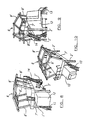
- an accommodation assembly for use as a temporary studio in outside broadcasting, comprises four (only two shown) vertical support legs 2 each comprising a base leg member 3 with a foot 4 resting on the ground. To each base member 3 is pivotally connected a main leg member 5.
- An accommodation structure 6, as shown in Figure 4 at ground level and in Figures 5A and 5B at an elevation above ground level, comprises a generally horizontal floor element 7, a plurality of wall elements 8 whose lower ends are secured to respective sides of the floor element 7 and which are inclined to the vertical, and a roof element 9 which is secured firmly to the upper ends of the wall elements 8.
- components of the accommodation assembly such as, the vertical support legs 2 and the floor, wall and roof elements 7 to 9 of the accommodation structure 6, are of an open framework construction, although in Figures 8 to 10, those components have been clad, as indicated at 2' and 7' to 9'.
- the four base leg members 3 are located at ground level with their feet 4 on the ground, and the floor element 7 of the accommodation structure 6 is mounted upon those base leg members 3 at each corner thereof, as shown in Figure 1.
- Main leg members 5, which are pivotally connected at their lower ends to respective base leg members 3, are in an initial, generally horizontal position and, as such, cannot be seen in Figure 1.
- the four main leg members 5 are pivoted with respect to the base leg members 3 into their vertical positions, as shown in Figure 2, to form the four erected support legs 2.
- the roof element 9 is then mounted upon the support legs 2, as shown in Figure 3, and raised into the position shown in Figure 4.
- the roof element 9 is then supported above the floor element 7 by the six spaced wall elements 8 which are inclined outwardly and to the vertical.
- each electric hoist motor 10 mounted securely thereto.
- Each electric hoist motor 10 is provided with a chain 11' which extends upwardly on either side and exterior of the associated support leg 2 and over a roller beam 11 which is located at the top of the support leg 2 and comprises two pulleys (not shown) arranged such that the load exerted upon the support leg 2 when being self-climbed by the erected accommodation structure 6, is distributed substantially evenly on both sides of the leg 2, to maintain the stability thereof.
- each electric hoist motor 10 is connected operably with its associated support leg 2 via the chain 11', which may be double-reaved, to provide the self-climbing ability of the erected accommodation structure 6.
- the accommodation structure 6 when erected at ground level, as shown in Figure 4, can self-climb the four support legs 2 to an elevation above ground level, as shown in Figures 5A and 5B.
- the accommodation structure 6 can be secured firmly to the top end of each support leg 2.
- FIG. 5B an outside broadcast trailer 12 is shown parked in the space provided between the underside of the floor element 7 of the now-elevated accommodation structure 6 and ground level.
- Figures 6 and 7 show side and end views of the elevated accommodation structure 6 with the trailer 12 parked thereunder.
- the clad floor, wall and roof elements 7' to 9', as well as the clad support legs 2', are shown in Figures 8 to 10. Additional cladding (not shown) can be used to provide a substantially closed, elevated accommodation structure 6, with doors and windows where necessary.
- Figures 8 to 10 also show stairways 13, 14 for providing access to the parked trailer 12 and the elevated accommodation structure 6, respectively.
- the invention provides temporary accommodation which is suitable for use in limited spaces, such as the paddocks or other service areas at, say, motor racing venues, thereby increasing, and usually doubling, the amount of available working space.
- accommodation assembly has one accommodation structure 6, it is to be appreciated that two or more such structures 6 can be provided, whereby each can self-climb the support legs 2, in turn, to a required elevation above ground level, thus providing a multi-storey accommodation assembly.
- the uppermost accommodation structure 6 has a roof element 9, in which case, the floor element 7 of an upper accommodation structure 6 may serve also as a flat roof element of the lower structure 6 immediately below.
Landscapes
- Engineering & Computer Science (AREA)
- Architecture (AREA)
- Civil Engineering (AREA)
- Structural Engineering (AREA)
- Tents Or Canopies (AREA)
- Catalysts (AREA)
- Electrical Discharge Machining, Electrochemical Machining, And Combined Machining (AREA)
- Vehicle Body Suspensions (AREA)
- Sewage (AREA)
- Cultivation Receptacles Or Flower-Pots, Or Pots For Seedlings (AREA)
- Residential Or Office Buildings (AREA)
- Valve-Gear Or Valve Arrangements (AREA)
- Devices For Conveying Motion By Means Of Endless Flexible Members (AREA)
- Cylinder Crankcases Of Internal Combustion Engines (AREA)
- Conveying And Assembling Of Building Elements In Situ (AREA)
- Bridges Or Land Bridges (AREA)
Claims (20)
- Unterbringungs-Baugruppe, welche aufweist:dadurch gekennzeichnet, dass die Unterbringungs-Baugruppe interimistisch ist, und dass die Mehrzahl von Stützbeinen (2) verschwenkbar an Basis-Fußteilen (3) angeordnet ist, damit sie auf den Basis-Fußteilen (3) beim Aufrichten direkt vom Bodenniveau nach oben stehen, wobei die Basis-Fußteile (3) direkt auf dem Boden angeordnet sind.Eine Mehrzahl von Stützbeinen (2), die so aufrichtbar sind, dass sie vom Boden nach oben stehen;Bauelemente (7, 8, 9), die zu einem Unterbringungsbau (6) aufrichtbar sind; und Mittel (10, 11, 11'), welche so angeordnet sind, dass sie nach dem Aufrichten des Unterbringungsbaus (6) dessen Selbstanstieg an den aufgerichteten Stützbeinen (2) von der Bodenhöhe zu einer darüber liegenden Höhe bewirken,
- Baugruppe nach Anspruch 1, bei welcher die aufgerichteten Stützbeine (2) einen Raum definieren, wobei der Unterbringungsbau so angeordnet ist, dass er nach dem Aufrichten zwischen den Stützbeinen (2) selbst an den aufgerichteten Stützbeinen (2) hochsteigt, um einen zugänglichen Raum in Bodenhöhe zu definieren, welcher durch den erhöhten Unterbringungsbau (6) und die Stützbeine (2) definiert und durch die Öffnungen zwischen den Stützbeinen (2) zugänglich ist.
- Baugruppe nach Anspruch 1 oder 2, bei welcher die Bauelemente (7, 8, 9) der Unterbringungs-Baugruppe (6) Boden-, Wand- und/oder Dachelemente aufweisen.
- Baugruppe nach Anspruch 1, 2, oder 3, bei welcher der Unterbringungsbau (6) nach der Errichtung einen im wesentlichen rechteckförmigen Grundriss und an jedem Eck ein Stützbein (2) aufweist.
- Baugruppe nach einem der vorhergehenden Ansprüche, bei welcher die Mittel (10, 11, 11') für den Selbstanstieg jeweils eine elektrische Hebeanordnung pro zugeordnetes Stützbein (2) in dessen aufgerichtetem Zustand aufweisen.
- Baugruppe nach Anspruch 5, bei welcher die elektrischen Hebeanordnungen jeweils einen Elektromotor (10) aufweisen, der an dem aufgerichteten Unterbringungsbau (6) befestigt ist.
- Baugruppe nach Anspruch 6, bei welcher die Elektromotoren (10) jeweils in Wirkverbindung mit einem länglichen flexiblen Glied (11'), z.B. einer Kette, stehen, welche sich längs des zugeordneten Stützbeins (2) nach dessen Aufrichtung nach oben und über eine Rolle (11) erstreckt, die am oberen Endbereich des nach oben stehenden Stützbeins (2) angeordnet ist.
- Baugruppe nach Anspruch 7, bei welcher sich das längliche flexible Glied (11') über zwei Rollen (11) am oberen Endbereich des nach oben stehenden Stützbeins (2) erstreckt, wobei die Rollen (11) einen Kettenbaum bilden.
- Baugruppe nach Anspruch 8, bei welcher das längliche flexible Glied (11') bezüglich des Elektromotors (10) und des Kettenbaums (11) doppelseilig ausgebildet ist, in der Weise, dass die auf das Stützbein (2) wirkende Last, wenn am Stützbein der aufgerichtete Unterbringungsbau (6) selbst hochsteigt, im wesentlichen gleichförmig auf beide Seiten des Stützbeins (2) verteilt ist.
- Baugruppe nach Anspruch 7, 8 oder 9, bei welcher sich das längliche, flexible Glied (11') an der Außenseite des zugeordneten Stützbeins (2) nach oben erstreckt.
- Baugruppe nach einem der vorhergehenden Ansprüche, bei welcher der aufgerichtete Unterbringungsbau (6) so angeordnet ist, dass er fest an jedem nach oben stehenden Stützbein (2) in einer gewünschten Höhe oberhalb der Bodenhöhe befestigt ist, nachdem bewirkt wurde, dass er selbst die Stützbeine (2) hochsteigt.
- Baugruppe nach einem der vorhergehenden Ansprüche, welche eine Mehrzahl von Unterbringungsbauten (6) aufweist, die zu einem mehrstöckigen Bauwerk aus solchen Unterbringungsbauten (6) aufrichtbar sind.
- Aufgerichteter Unterbringungsbau (6), welcher errichtet ist ausgehend von einer interimistischen Unterbringungs-Baugruppe nach einem der vorhergehenden Ansprüche.
- Verfahren zum Aufrichten eines interimistischen Unterbringungsbaus in einer Höhe oberhalb der Bodenhöhe, welches Verfahren folgende Schritte aufweist:dadurch gekennzeichnet, dass der Unterbringungsbau interimistisch ist und dass die Stützbeine (2) in der Weise aufgerichtet werden, dass sie vom Bodenniveau dadurch nach oben stehen, dass sie an Basis-Fußteilen (3) verschwenkt werden, welche direkt auf dem Boden angeordnet sind.Aufrichten einer Mehrzahl von Stützbeinen (2), so dass sie vom Bodenniveau nach oben stehen;Errichten eines Unterbringungsbaus (6) an den Basen der nach oben stehenden Stützbeine (2);Bewirken, dass der so errichtete Unterbringungsbau (6) selbst an den Beinen (2) in eine Höhe oberhalb des Bodenniveaus hochsteigt,
- Verfahren nach Anspruch 14, bei welchem ein Bodenelement (7) der Aufnahmekonstruktion (6) auf einem Basis-Fußteil (3) jedes Stützbeins (2) montiert wird, an welchem Basis-Fußteil (3) ein Haupt-Stützglied (5) in einer unteren, etwa waagerechten Lage verschwenkbar befestigt ist;
die Haupt-Stützglieder (5) bezüglich ihrer Basis-Fußteile (3) nach oben verschwenkt werden, um eine entsprechende Zahl nach oben stehender Stützbeine (2) zu erhalten;
ein Dachelement (9) des Unterbringungsbaus (6) errichtet und oberhalb des Bodenelements (7) durch dazwischen befestigte Wandelemente (8) abgestützt wird;
bewirkt wird, dass der so errichtete Unterbringungsbau (6) selbst an den nach oben stehenden Stützbeinen (2), auf denen er montiert ist, in eine Höhe oberhalb des Bodenniveaus hochsteigt. - Verfahren nach Anspruch 15, bei welchem mindestens eines der Boden-, Wand- und Dachelemente (7, 8, 9) mit einer Verkleidung versehen wird, um eine im wesentlichen geschlossene Unterbringung in einer Höhe oberhalb des Bodenniveaus bereit zu stellen.
- Verfahren nach Anspruch 16, bei welchem das mindestens eine Boden-, Wand- und Dachelement (7, 8, 9) mit einer Verkleidung versehen wird, entweder bevor bewirkt wurde, dass der aufgerichtete Unterbringungsbau (6) an den nach oben stehenden Stützbeinen (2) selbst nach oben steigt, oder danach.
- Verfahren nach einem der Ansprüche 14 bis 17, bei welchem die nach oben stehenden Stützbeine (2) mit einer Verkleidung versehen werden.
- Verfahren nach einem der Ansprüche 14 bis 18, bei welchem ein Raum zwischen dem erhöhten Unterbringungsbau (6) und dem Bodenniveau bereit gestellt wird.
- Verfahren nach einem der Ansprüche 14 bis 19, bei welchem eine Mehrzahl von Unterbringungsbauten (6) errichtet und bewirkt wird, dass die so errichteten Bauten (6) selbst nacheinander an den Beinen (2) hochsteigen, um eine mehrstöckige Behelfs-Unterbringungs-Baugruppe bereit zu stellen.
Applications Claiming Priority (3)
| Application Number | Priority Date | Filing Date | Title |
|---|---|---|---|
| GB9705768 | 1997-03-20 | ||
| GB9705768A GB2323106B (en) | 1997-03-20 | 1997-03-20 | Elevated accomodation assembly |
| PCT/GB1998/000836 WO1998042935A1 (en) | 1997-03-20 | 1998-03-19 | Elevated accommodation assembly |
Publications (2)
| Publication Number | Publication Date |
|---|---|
| EP0968343A1 EP0968343A1 (de) | 2000-01-05 |
| EP0968343B1 true EP0968343B1 (de) | 2003-07-30 |
Family
ID=10809560
Family Applications (1)
| Application Number | Title | Priority Date | Filing Date |
|---|---|---|---|
| EP98910887A Expired - Lifetime EP0968343B1 (de) | 1997-03-20 | 1998-03-19 | Erhöhte aufenthaltseinheit |
Country Status (8)
| Country | Link |
|---|---|
| US (1) | US6357550B1 (de) |
| EP (1) | EP0968343B1 (de) |
| AT (1) | ATE246296T1 (de) |
| AU (1) | AU6511398A (de) |
| CA (1) | CA2283970A1 (de) |
| DE (1) | DE69816793T2 (de) |
| GB (1) | GB2323106B (de) |
| WO (1) | WO1998042935A1 (de) |
Families Citing this family (6)
| Publication number | Priority date | Publication date | Assignee | Title |
|---|---|---|---|---|
| RU2270305C1 (ru) * | 2004-07-07 | 2006-02-20 | Владимир Владимирович Соловьев | Здание над входом в подземный переход |
| US9528287B2 (en) * | 2013-06-10 | 2016-12-27 | Dirtt Environmental Solutions, Ltd. | Angled wall connection devices, systems, and methods |
| GB2551556B (en) * | 2016-06-22 | 2021-09-08 | Beaverfit Ltd | Fast-rope training apparatus |
| US10851552B1 (en) * | 2018-03-14 | 2020-12-01 | Cube Dynamics, LLC | Portable personal use module and methods of use |
| US10155128B1 (en) * | 2018-05-01 | 2018-12-18 | Maria Sophia Lefevre | Shed and modular playset accessory system |
| US11242680B2 (en) * | 2018-11-30 | 2022-02-08 | Bahler Ip, Llc | Building system and method thereof |
Family Cites Families (12)
| Publication number | Priority date | Publication date | Assignee | Title |
|---|---|---|---|---|
| US297335A (en) * | 1884-04-22 | Skeleton tower | ||
| US3568796A (en) * | 1969-04-30 | 1971-03-09 | Lawrence Edward Stanhope | Fruit workers platform |
| FR2219282A1 (de) | 1973-02-23 | 1974-09-20 | Dziewolski Richard | |
| US4512117A (en) * | 1982-08-06 | 1985-04-23 | Interlock Structures International, Inc. | Modular proscenium theatre |
| SU1099027A1 (ru) * | 1983-03-25 | 1984-06-23 | Тюменский инженерно-строительный институт | Подмости |
| FR2549029B1 (fr) * | 1983-07-11 | 1987-01-30 | Comabi Sa | Elevateur comportant au moins un mat telescopique |
| DE3443023C2 (de) * | 1984-11-26 | 1987-03-12 | Johann B. 6530 Bingen Pfeifer | Montagegerüst mit einer Hebebühne |
| US4719716A (en) * | 1986-12-29 | 1988-01-19 | Chrisley Jr Tom H | Round deer stand |
| FR2615220B1 (fr) | 1987-05-13 | 1992-07-31 | Duez Alain | Procede de construction successive de planchers superposes de batiment |
| GB2250731B (en) * | 1990-08-09 | 1994-06-01 | Mitsubishi Heavy Ind Ltd | Apparatus and method for constructing a building |
| AU651616B2 (en) * | 1990-10-08 | 1994-07-28 | Kajima Corporation | Process for constructing frame and erection |
| US5870872A (en) * | 1997-11-11 | 1999-02-16 | Stuppy, Incorporated | Applicator for ceiling panels of light tunnel |
-
1997
- 1997-03-20 GB GB9705768A patent/GB2323106B/en not_active Expired - Fee Related
-
1998
- 1998-03-19 AU AU65113/98A patent/AU6511398A/en not_active Abandoned
- 1998-03-19 DE DE69816793T patent/DE69816793T2/de not_active Expired - Fee Related
- 1998-03-19 AT AT98910887T patent/ATE246296T1/de not_active IP Right Cessation
- 1998-03-19 US US09/381,215 patent/US6357550B1/en not_active Expired - Fee Related
- 1998-03-19 EP EP98910887A patent/EP0968343B1/de not_active Expired - Lifetime
- 1998-03-19 WO PCT/GB1998/000836 patent/WO1998042935A1/en not_active Ceased
- 1998-03-19 CA CA002283970A patent/CA2283970A1/en not_active Abandoned
Also Published As
| Publication number | Publication date |
|---|---|
| EP0968343A1 (de) | 2000-01-05 |
| AU6511398A (en) | 1998-10-20 |
| DE69816793T2 (de) | 2004-06-03 |
| CA2283970A1 (en) | 1998-10-01 |
| DE69816793D1 (de) | 2003-09-04 |
| WO1998042935A1 (en) | 1998-10-01 |
| GB2323106A (en) | 1998-09-16 |
| ATE246296T1 (de) | 2003-08-15 |
| US6357550B1 (en) | 2002-03-19 |
| GB9705768D0 (en) | 1997-05-07 |
| GB2323106B (en) | 2001-10-24 |
Similar Documents
| Publication | Publication Date | Title |
|---|---|---|
| US4930270A (en) | Building systems | |
| US9611637B2 (en) | Prefabricated foldable building module | |
| US4598510A (en) | Modular and expandable platform system | |
| US8959849B1 (en) | Light steel frame structure for deck | |
| CA2682422C (en) | Gazebo structure | |
| US4882883A (en) | Architectural modular system | |
| US5313756A (en) | Sun deck and frame therefor | |
| US20100218436A1 (en) | Transportable building module with two structures | |
| GB2547116A (en) | Building structure and method | |
| US7325362B1 (en) | Steel roof truss system | |
| US6357550B1 (en) | Elevated accommodation assembly | |
| US7832155B1 (en) | Drop floor construction and method for park model home | |
| JP2843016B2 (ja) | 折畳み式階段ユニットボックスおよびこれを用いた建物 | |
| EP1507053B1 (de) | Modulare Plattform | |
| US2903752A (en) | Building construction | |
| US20050252150A1 (en) | Module based building system | |
| US20070163205A1 (en) | Method for constructing decks | |
| CA2363809A1 (en) | Narrow buttress system structure for swimming pools | |
| WO2004097130A1 (en) | A transportable building and self-levelling chassis therefor | |
| CA2423353A1 (en) | Prefabricated building system | |
| JP3124152B2 (ja) | 倒壊防止フレーム | |
| AU593917B2 (en) | Building systems | |
| CA2462467A1 (en) | Prefabricated building system | |
| RU6002U1 (ru) | Здание, преимущественно торговый павильон | |
| EP1179650A1 (de) | Verbesserte bühne |
Legal Events
| Date | Code | Title | Description |
|---|---|---|---|
| PUAI | Public reference made under article 153(3) epc to a published international application that has entered the european phase |
Free format text: ORIGINAL CODE: 0009012 |
|
| 17P | Request for examination filed |
Effective date: 19991011 |
|
| AK | Designated contracting states |
Kind code of ref document: A1 Designated state(s): AT BE CH DE DK ES FI FR GB GR IE IT LI LU MC NL PT SE |
|
| 17Q | First examination report despatched |
Effective date: 20020122 |
|
| GRAH | Despatch of communication of intention to grant a patent |
Free format text: ORIGINAL CODE: EPIDOS IGRA |
|
| GRAH | Despatch of communication of intention to grant a patent |
Free format text: ORIGINAL CODE: EPIDOS IGRA |
|
| GRAA | (expected) grant |
Free format text: ORIGINAL CODE: 0009210 |
|
| AK | Designated contracting states |
Designated state(s): AT BE CH DE DK ES FI FR GB GR IE IT LI LU MC NL PT SE |
|
| PG25 | Lapsed in a contracting state [announced via postgrant information from national office to epo] |
Ref country code: NL Free format text: LAPSE BECAUSE OF FAILURE TO SUBMIT A TRANSLATION OF THE DESCRIPTION OR TO PAY THE FEE WITHIN THE PRESCRIBED TIME-LIMIT Effective date: 20030730 Ref country code: LI Free format text: LAPSE BECAUSE OF FAILURE TO SUBMIT A TRANSLATION OF THE DESCRIPTION OR TO PAY THE FEE WITHIN THE PRESCRIBED TIME-LIMIT Effective date: 20030730 Ref country code: IT Free format text: LAPSE BECAUSE OF FAILURE TO SUBMIT A TRANSLATION OF THE DESCRIPTION OR TO PAY THE FEE WITHIN THE PRESCRIBED TIME-LIMIT;WARNING: LAPSES OF ITALIAN PATENTS WITH EFFECTIVE DATE BEFORE 2007 MAY HAVE OCCURRED AT ANY TIME BEFORE 2007. THE CORRECT EFFECTIVE DATE MAY BE DIFFERENT FROM THE ONE RECORDED. Effective date: 20030730 Ref country code: FI Free format text: LAPSE BECAUSE OF FAILURE TO SUBMIT A TRANSLATION OF THE DESCRIPTION OR TO PAY THE FEE WITHIN THE PRESCRIBED TIME-LIMIT Effective date: 20030730 Ref country code: CH Free format text: LAPSE BECAUSE OF FAILURE TO SUBMIT A TRANSLATION OF THE DESCRIPTION OR TO PAY THE FEE WITHIN THE PRESCRIBED TIME-LIMIT Effective date: 20030730 Ref country code: BE Free format text: LAPSE BECAUSE OF FAILURE TO SUBMIT A TRANSLATION OF THE DESCRIPTION OR TO PAY THE FEE WITHIN THE PRESCRIBED TIME-LIMIT Effective date: 20030730 Ref country code: AT Free format text: LAPSE BECAUSE OF FAILURE TO SUBMIT A TRANSLATION OF THE DESCRIPTION OR TO PAY THE FEE WITHIN THE PRESCRIBED TIME-LIMIT Effective date: 20030730 |
|
| REG | Reference to a national code |
Ref country code: GB Ref legal event code: FG4D |
|
| REG | Reference to a national code |
Ref country code: CH Ref legal event code: EP |
|
| REG | Reference to a national code |
Ref country code: IE Ref legal event code: FG4D |
|
| REF | Corresponds to: |
Ref document number: 69816793 Country of ref document: DE Date of ref document: 20030904 Kind code of ref document: P |
|
| PG25 | Lapsed in a contracting state [announced via postgrant information from national office to epo] |
Ref country code: SE Free format text: LAPSE BECAUSE OF FAILURE TO SUBMIT A TRANSLATION OF THE DESCRIPTION OR TO PAY THE FEE WITHIN THE PRESCRIBED TIME-LIMIT Effective date: 20031030 Ref country code: GR Free format text: LAPSE BECAUSE OF FAILURE TO SUBMIT A TRANSLATION OF THE DESCRIPTION OR TO PAY THE FEE WITHIN THE PRESCRIBED TIME-LIMIT Effective date: 20031030 Ref country code: DK Free format text: LAPSE BECAUSE OF FAILURE TO SUBMIT A TRANSLATION OF THE DESCRIPTION OR TO PAY THE FEE WITHIN THE PRESCRIBED TIME-LIMIT Effective date: 20031030 |
|
| PG25 | Lapsed in a contracting state [announced via postgrant information from national office to epo] |
Ref country code: ES Free format text: LAPSE BECAUSE OF FAILURE TO SUBMIT A TRANSLATION OF THE DESCRIPTION OR TO PAY THE FEE WITHIN THE PRESCRIBED TIME-LIMIT Effective date: 20031110 |
|
| NLV1 | Nl: lapsed or annulled due to failure to fulfill the requirements of art. 29p and 29m of the patents act | ||
| PG25 | Lapsed in a contracting state [announced via postgrant information from national office to epo] |
Ref country code: PT Free format text: LAPSE BECAUSE OF FAILURE TO SUBMIT A TRANSLATION OF THE DESCRIPTION OR TO PAY THE FEE WITHIN THE PRESCRIBED TIME-LIMIT Effective date: 20031230 |
|
| REG | Reference to a national code |
Ref country code: CH Ref legal event code: PL |
|
| PGFP | Annual fee paid to national office [announced via postgrant information from national office to epo] |
Ref country code: GB Payment date: 20040317 Year of fee payment: 7 |
|
| PG25 | Lapsed in a contracting state [announced via postgrant information from national office to epo] |
Ref country code: LU Free format text: LAPSE BECAUSE OF NON-PAYMENT OF DUE FEES Effective date: 20040319 Ref country code: IE Free format text: LAPSE BECAUSE OF NON-PAYMENT OF DUE FEES Effective date: 20040319 |
|
| PGFP | Annual fee paid to national office [announced via postgrant information from national office to epo] |
Ref country code: FR Payment date: 20040322 Year of fee payment: 7 |
|
| PGFP | Annual fee paid to national office [announced via postgrant information from national office to epo] |
Ref country code: DE Payment date: 20040330 Year of fee payment: 7 |
|
| PG25 | Lapsed in a contracting state [announced via postgrant information from national office to epo] |
Ref country code: MC Free format text: LAPSE BECAUSE OF NON-PAYMENT OF DUE FEES Effective date: 20040331 |
|
| ET | Fr: translation filed | ||
| PLBE | No opposition filed within time limit |
Free format text: ORIGINAL CODE: 0009261 |
|
| STAA | Information on the status of an ep patent application or granted ep patent |
Free format text: STATUS: NO OPPOSITION FILED WITHIN TIME LIMIT |
|
| 26N | No opposition filed |
Effective date: 20040504 |
|
| REG | Reference to a national code |
Ref country code: IE Ref legal event code: MM4A |
|
| PG25 | Lapsed in a contracting state [announced via postgrant information from national office to epo] |
Ref country code: GB Free format text: LAPSE BECAUSE OF NON-PAYMENT OF DUE FEES Effective date: 20050319 |
|
| PG25 | Lapsed in a contracting state [announced via postgrant information from national office to epo] |
Ref country code: DE Free format text: LAPSE BECAUSE OF NON-PAYMENT OF DUE FEES Effective date: 20051001 |
|
| GBPC | Gb: european patent ceased through non-payment of renewal fee |
Effective date: 20050319 |
|
| PG25 | Lapsed in a contracting state [announced via postgrant information from national office to epo] |
Ref country code: FR Free format text: LAPSE BECAUSE OF NON-PAYMENT OF DUE FEES Effective date: 20051130 |
|
| REG | Reference to a national code |
Ref country code: FR Ref legal event code: ST Effective date: 20051130 |