EP0968353B1 - Geschosslöchersystem für vollbohrungen - Google Patents
Geschosslöchersystem für vollbohrungen Download PDFInfo
- Publication number
- EP0968353B1 EP0968353B1 EP98908978A EP98908978A EP0968353B1 EP 0968353 B1 EP0968353 B1 EP 0968353B1 EP 98908978 A EP98908978 A EP 98908978A EP 98908978 A EP98908978 A EP 98908978A EP 0968353 B1 EP0968353 B1 EP 0968353B1
- Authority
- EP
- European Patent Office
- Prior art keywords
- tubular assembly
- bore
- well
- tubular
- explosive charges
- Prior art date
- Legal status (The legal status is an assumption and is not a legal conclusion. Google has not performed a legal analysis and makes no representation as to the accuracy of the status listed.)
- Expired - Lifetime
Links
- 238000010304 firing Methods 0.000 claims description 72
- 239000002360 explosive Substances 0.000 claims description 39
- 238000005474 detonation Methods 0.000 claims description 33
- 238000004519 manufacturing process Methods 0.000 claims description 21
- 239000000463 material Substances 0.000 claims description 19
- 238000000034 method Methods 0.000 claims description 15
- 239000012530 fluid Substances 0.000 claims description 8
- 229910052782 aluminium Inorganic materials 0.000 claims description 5
- XAGFODPZIPBFFR-UHFFFAOYSA-N aluminium Chemical compound [Al] XAGFODPZIPBFFR-UHFFFAOYSA-N 0.000 claims description 5
- 239000000919 ceramic Substances 0.000 claims description 5
- 239000002800 charge carrier Substances 0.000 claims description 4
- 239000011521 glass Substances 0.000 claims description 4
- 239000012255 powdered metal Substances 0.000 claims description 4
- 239000002131 composite material Substances 0.000 claims description 3
- 239000012634 fragment Substances 0.000 claims description 3
- 238000007789 sealing Methods 0.000 claims description 3
- 239000002023 wood Substances 0.000 claims description 3
- HCHKCACWOHOZIP-UHFFFAOYSA-N Zinc Chemical compound [Zn] HCHKCACWOHOZIP-UHFFFAOYSA-N 0.000 claims description 2
- 229910001297 Zn alloy Inorganic materials 0.000 claims description 2
- 239000011368 organic material Substances 0.000 claims description 2
- 239000000123 paper Substances 0.000 claims description 2
- 239000004033 plastic Substances 0.000 claims description 2
- 229920003023 plastic Polymers 0.000 claims description 2
- 229910052725 zinc Inorganic materials 0.000 claims description 2
- 239000011701 zinc Substances 0.000 claims description 2
- 239000000203 mixture Substances 0.000 claims 1
- 238000009527 percussion Methods 0.000 description 4
- 230000008878 coupling Effects 0.000 description 3
- 238000010168 coupling process Methods 0.000 description 3
- 238000005859 coupling reaction Methods 0.000 description 3
- 238000005553 drilling Methods 0.000 description 3
- 230000015572 biosynthetic process Effects 0.000 description 2
- 239000007789 gas Substances 0.000 description 2
- 229910052751 metal Inorganic materials 0.000 description 2
- 239000002184 metal Substances 0.000 description 2
- 239000000843 powder Substances 0.000 description 2
- 229910001018 Cast iron Inorganic materials 0.000 description 1
- 239000000428 dust Substances 0.000 description 1
- 239000012729 immediate-release (IR) formulation Substances 0.000 description 1
- 239000003999 initiator Substances 0.000 description 1
- 229910001092 metal group alloy Inorganic materials 0.000 description 1
- 238000012986 modification Methods 0.000 description 1
- 230000004048 modification Effects 0.000 description 1
Images
Classifications
-
- E—FIXED CONSTRUCTIONS
- E21—EARTH OR ROCK DRILLING; MINING
- E21B—EARTH OR ROCK DRILLING; OBTAINING OIL, GAS, WATER, SOLUBLE OR MELTABLE MATERIALS OR A SLURRY OF MINERALS FROM WELLS
- E21B43/00—Methods or apparatus for obtaining oil, gas, water, soluble or meltable materials or a slurry of minerals from wells
- E21B43/11—Perforators; Permeators
- E21B43/116—Gun or shaped-charge perforators
- E21B43/117—Shaped-charge perforators
-
- E—FIXED CONSTRUCTIONS
- E21—EARTH OR ROCK DRILLING; MINING
- E21B—EARTH OR ROCK DRILLING; OBTAINING OIL, GAS, WATER, SOLUBLE OR MELTABLE MATERIALS OR A SLURRY OF MINERALS FROM WELLS
- E21B43/00—Methods or apparatus for obtaining oil, gas, water, soluble or meltable materials or a slurry of minerals from wells
- E21B43/11—Perforators; Permeators
- E21B43/119—Details, e.g. for locating perforating place or direction
Definitions
- the present invention relates generally to a tubing conveyed perforating gun system of the type used to perforate a well bore for the production of well bore fluids and, specifically, to such a system with internal components which disintegrate upon detonation of the associated firing system so that the interior bore of the tubing string is fully open after detonation.
- the casing or liner is a metal, cylindrical conduit which must be punctured or perforated over the desired production interval in order to produce well bore fluids once drilling is complete.
- a perforating gun which utilizes some form of fired projectile and an explosive charge is used to perforate the casing or liner to begin production from the well.
- Prior perforating gun techniques have either utilized tools which were run on a wireline or cable or have utilized tubing conveyed devices which were run on a tubing string to a desired depth in a well bore.
- Tubing conveyed devices have certain advantages over wireline methods, for example, in allowing safe, immediate release of formation pressure at maximum pressure differentials into the tubing string.
- the tubing With tubing conveyed perforating systems, the tubing can be run into position, a packer set to seal off the well bore, and the surface well head equipment can be installed. The packer setting can be checked by circulating fluid under pressure through the well annulus or through the well tubing string. Once the surface work is completed and tested for safety, the perforating gun can be fired to bring in the well. Since all surface work is completed before the perforating gun is fired, operating safety is enhanced.
- the perforating gun has been fired and the casing is perforated, there are basically three methods for dealing with the remaining perforating apparatus: (1) the perforating guns can be dropped to the bottom of the well bore with a mechanical gun release or automatic gun release; (2) the guns can be removed from the well; or (3) the guns can remain on the tubing.
- the first alternative was generally the best, since releasing the perforating gun portion of the apparatus from the remainder of the tubing string provided a greater flow area through the tubing string for production of well bore fluids and also allowed tools and other devices to be run through the interior bore of the tubing string without contacting the perforating gun apparatus.
- this choice generally required an extra "rat hole" to be drilled.
- Removing the perforating gun portion of the apparatus from the well also offered the advantages of a full open bore but required a separate trip out of the well adding to the overall expense and risking damage to the productivity of the well.
- the third alternative of leaving the guns in the well bore was the least desirable since the perforating apparatus cannot be left adjacent the producing area in the well if production logging or other work is desired.
- Examples of prior art well perforating guns include the wireline conveyed perforating systems (i.e. not tubing conveyed systems) of US 2968243 and US 3211093, as well as the tubing conveyed systems of US 2876843 and US 3706344 which require the large perforating apparatus to be released from the assembly into a "rat hole" after detonation of the explosive charges contained therein.
- the present invention has as its object to provide a tubing conveyed perforating apparatus which can be conveyed on production casing or tubing, positioned in a well bore adjacent a producing formation and fired and which automatically becomes full bore thereafter to allow logging tools to be conveyed through the gun portion of the apparatus.
- Another object of the invention is to provide a tubing conveyed perforating apparatus which provides a tubing string with a full open interior bore after firing and without requiring a separate trip out of the well or the drilling of an additional "rat hole.”
- Another object of the invention is to provide a tubing conveyed perforating apparatus which features a tubular assembly including a plurality of tubular sections which are threadedly connected by external collars, whereby the interior bore of the tubular assembly adjacent the firing section is of generally constant internal diameter.
- Another object of the invention is to provide such a perforating apparatus with a firing head which is either automatically ejected after firing or which can be pulled via a wireline or slickline to the well surface.
- Another object of the invention is to provide a perforating apparatus with internal components made of materials which will disintegrate upon detonation.
- Another object of the invention is to provide a perforating apparatus which is initially sealed at an upper end by a firing head and which is initially sealed at a lower end by a self-releasing plug so that the charge carrying portion of the device is initially isolated in an atmospheric chamber.
- Another object of the invention is to provide such an apparatus which is simple in design and economical to manufacture.
- the tubing conveyed perforating apparatus of the invention includes a tubular assembly made up of a plurality of tubular sections. Each of the tubular sections has a generally cylindrical exterior and a concentric interior bore.
- the tubular assembly has an upper connecting end for connection in a tubular string extending to the well surface and a lower end.
- An elongate charge holder is located within the interior bore of the tubular assembly.
- a plurality of explosive charges are mounted on the charge holder.
- a plurality of elongate charge holders can be arranged end to end and extend downwardly within the tubular assembly.
- the tubular sections of the tubular assembly which surround the charge holders are threadedly connected by external collars, whereby the interior bore of the tubular assembly which contains the charge holders is of generally constant internal diameter.
- a firing head is provided for detonating the explosive charges to perforate the surrounding well bore.
- the charge holder and plurality of explosive charges are comprised of materials which disintegrate upon detonation of the explosive charges, whereby the interior bore of the tubular assembly is fully open after detonation.
- the firing head includes release means for automatically releasing the firing head upon detonation of the explosive charges, thereby allowing the firing head to fall through the interior bore of the tubular assembly into the well bore below the apparatus.
- the firing head can include a connecting end for connection to a retrieval apparatus which is run from the well surface, whereby the firing head can be pulled from the well bore upon detonation.
- the firing head is preferably located above the elongate charge carriers within the interior bore of the tubular assembly and initially seals off the interior bore thereof from above.
- a self-releasing plug is mounted at the lower end of the tubular assembly for initially sealing the interior bore from below.
- the interior bore of the tubular assembly between the firing head and self-releasing plug is initially an air-filled, atmospheric chamber.
- a tubing conveyed perforating apparatus and a packer means are suspended from a tubing string at a subterranean location within a well bore.
- the packer is set within the well bore at a position which isolates a lower borehole portion of the well bore from an upper borehole portion thereof and which locates the perforating apparatus adjacent the production interval.
- the perforating apparatus is actuated to perforate the well casing adjacent the production interval to thereby allow production fluids to flow through the perforated interval, through a surrounding annular area of the well and upwardly through the tubing string to the well surface.
- the charge holder and explosive charges which make up the internal components of the perforating apparatus are formed from a disintegratable material which disintegrates during detonation of the explosive charges, whereby the interior bore of the tubular assembly is fully open after detonation.
- the disintegratable components of the tubular assembly are initially isolated within the interior bore thereof at an upper end by the firing head and at the lower end by a self-releasing plug.
- the act of detonating the explosive charges releases the firing head and self-releasing plug from the apparatus, whereby the interior bore is fully open after detonation and substantial disintegration of the charge carrier and explosive charges.
- the firing head and self-releasing plug can be allowed to fall downwardly through the tubular assembly into the well bore below the apparatus or the firing head can be retrieved to the well surface after detonation.
- the production interval is then logged by lowering logging tools downwardly from the well surface through the tubing string and through the now open interior bore of the now perforated tubular assembly to the producing zone.
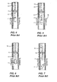
- Figures 4-7 show a prior art perforating operation using a tubing conveyed perforating gun which is dropped to the bottom of the well bore after firing.
- a typical prior art perforating system is shown which includes a perforating gun 11 which is run below a well packer 13 and which is connected to a tubing string 15 by a disconnect sub 17.
- the tubing string 15 extends to the well surface (not shown) of the cased well bore 19.
- the packer is set at the desired location which isolates a lower borehole portion 21 from an upper borehole portion 23 and which locates the perforating apparatus adjacent a production interval 25.
- the perforating apparatus 11 is then actuated to perforate the well casing 19 adjacent the production interval 25.
- This can be accomplished, in the case of a percussion detonated device by passing a weight down the interior of the tubing string from the well surface to contact a percussion detonator.
- a percussion detonated device By passing a weight down the interior of the tubing string from the well surface to contact a percussion detonator.
- Such devices are well known in the art, for example, United States Patent No. 2,876,843 to Huber, issued March 10, 1959, shows such a tubing conveyed perforating apparatus in which a weight contacts a percussion detonator to fire the perforating guns.
- the disconnect sub is then actuated to release the perforating apparatus, thereby allowing the apparatus to drop to the bottom of the well bore.
- this type technique has several disadvantages including the presence of additional relatively large debris in the well which must be accommodated by drilling a rat hole.
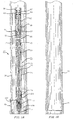
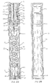
- the perforating apparatus 27 includes a tubular assembly made up of a plurality of tubular sections 31, 33, 35. Each tubular section has a generally cylindrical exterior and a generally concentric interior bore (37 in Figure 1A).
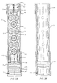
- the tubular assembly has an upper connecting end (not shown) for connection in the tubing string (15 in Figure 4) leading to the well surface and has a lower end (39 in Figure 3A).
- a plurality of elongate charge holders (41, 43 illustrated in Figures 2A and 3A) are located within the interior bore 37 of the tubular assembly and are ballistically connected by means of bi-directional booster sections (e.g. section 45 in Figure 3A).
- the booster sections 45 include upper and lower end caps 47, 49.
- a det cord 51 passes through a central bore of the booster components for actuating the depending explosive charges.
- a plurality of shaped explosive charges (53, 55 in Figures 2A and 3A) are mounted along the length of each of the charge holders 41, 43 and are arranged in a selected pattern and orientation for producing the desired perforating pattern upon detonation.
- the explosive charges 53, 55 are shaped charges which have special charge cases formed of a material which will vaporize upon detonation leaving only a very fine dust remnant.
- the preferred charge cases 57, 59 will be a commercially available zinc alloy ZA-5.
- the shaped charge cases can be made of any material or combination of materials which will disintegrate upon detonation such as metal alloys, powdered metals, aluminum, glass or ceramics or combinations thereof.
- the charge holders 41, 43 are preferably made from wood or other suitable rigid organic composite material that burns and essentially vaporizes upon detonation of the shaped charges. Any of the other internal alignment components, such as the booster transfer components 45 and end caps 47, 49 would be made of similar materials to that of the charge holder.
- wood or other rigid organic materials include powdered metals, composites, plastics, aluminum, zinc, paper, glass, ceramics or combinations thereof. It is only necessary that the disintegratable material not leave large size debris such as strips of metal behind upon detonation.
- Each of the tubular sections 29, 33 and 35 are generally cylindrical members having opposite externally threaded extents (61, 63 in Figure 2A) which are connected in the tubular assembly by means of external collars 65, 67, 69, whereby the interior bore 37 of the tubular assembly which contains the charge holders 41, 43 is of generally constant internal diameter.
- the I.D. of the assembly forms a generally slick interior surface after firing, as illustrated in Figures 1B-3B.
- a "tandem" connector is utilized to attach multiple guns together end to end.
- the collar type connection of the apparatus of the invention allows the perforating system to remain full bore after firing.
- integral joint (flush joint inside and outside) connections could also be employed.
- a conventional TCP firing head 71 is located above the elongate charge holders 41, 43 within the interior bore 37 of the tubular assembly.
- the firing head 71 includes an outer tubular body 73 which surrounds an inner tubular body 75, the inner tubular body having an internal bore 77 for containing a pyrotechnic material.
- Appropriately located O-ring seal sections 79, 81, 83 isolate the internal bore 77.
- a sub 85 has an internal bore 87 in which is located plug 89 having a bore 91 through which a firing pin 93 can travel upon release of the shear means such as pins 95, 97 which initially connect the firing piston 99 within an external coupling 101.
- downward pressure exerted on the upper end 99 of the firing head drives the firing pin 93 downwardly to strike the percussion initiator 103, igniting the pyrotechnic powder in the bore 77.
- the lower end 105 of the traditional firing head is threadedly received within an upper bore 107 of a novel support sub which includes a sub body 109 having an internal bore 111 containing a det cord which is ignited by the firing mechanism 113 of the head 71.
- the sub body 109 has a region of relatively greater external diameter 115 which contacts a seal surface 117 including 0-rings 119 of the specially machined tubular section 31 where it forms a sliding seal.
- the sub body 109 also has a region of lesser relative diameter 121 which is surrounded by a retaining sleeve 123 including an upper flange portion 124 and a lower flange portion 126.
- the retaining sleeve 123 initially prevents downward movement of the sub body 109 in the direction of the elongate charge holders 41.
- the retaining sleeve 123 is also surrounded by a collet 125 having upwardly extending collet fingers 127 which initially underlay the retaining sleeve 123 and contact a shoulder region thereof for supporting the retaining sleeve, and hence the sub body 109 in the position shown in Figure 2A.
- a sleeve 128 is provided to initially resist the upward movement of the retaining sleeve 123.
- FIG. 2B shows the interior of the special tubular section 31 and of the tubular section 33 after firing, the section 33 being perforated by holes 133, 135.
- the charge holders 41 and explosive charges 53 were contained within an air-filled, atmospheric chamber created between the O-ring seals 150 in the plug 145 and the O-ring seals 146, 148, 152, 154, 156 provided between each tubular section and external collar.
- the explosive charges are initially isolated in an atmospheric chamber from the surrounding well bore fluids.
- the tubular section 35 containing the second downwardly extending charge holder 43 terminates in a lower end member 39.
- Member 39 is a generally cylindrical body having an internally threaded surface 141 which threadedly engages the externally threaded lower extent 143 of the tubular section 35.
- the self-releasing plug 145 is located within the mouth opening 147 thereof below the charge carrier end cap 149.
- the self-releasing plug 145 is made of a frangible material such as a ceramic which will fragment into many pieces upon firing of the perforating system.
- the plug is a generally cylindrical disk having circumferential grooves for carrying external O-ring seals 150 and is initially held in position by means of one or more shear pins 151.
- the plug 145 could also be made from aluminum or cast iron.
- the tubing conveyed perforating apparatus of the invention is run into position on a tubing string, such as string 15 shown in Figure 4.
- the firing head is actuated, whereby the explosive powders within the bores 77, 111 ignite the explosive charges 53, 55 on the charge holders, thereby perforating the tubular sections 33, 35 and the surrounding well bore casing.
- the force of detonation causes opposite relative movement of the retaining sleeve 123 and its upper flange portion 124 and the collet fingers 127, releasing the firing head.
- the force of the detonation also shears the pins 151 allowing the bottom plug 145 to be ejected downwardly from the tubing assembly and/or fragments the plug.
- the perforating apparatus of the invention provides a full bore tubing string after firing so that logging tools and other instruments or devices can be run without danger of becoming stuck or damaged.
- the perforating apparatus of the invention provides an open bore subsequent to detonation without requiring that the perforating guns be dropped to the bottom of the well bore or without requiring a separate trip into the well to remove the guns.
- the design is simple and economical to manufacture.
- the firing head could be located on the bottom of the tool instead of the top. It is also envisioned that the firing system could be concentric to the gun I.D. with a full opening valve being utilized to block the tubing string I.D. In addition to the external collars used to join the tubing sections, the tubing connections could be integral joints, as well.
- the bottom, self-releasing plug could be made of frangible material which would disintegrate into pieces upon firing.
Landscapes
- Geology (AREA)
- Life Sciences & Earth Sciences (AREA)
- Engineering & Computer Science (AREA)
- Mining & Mineral Resources (AREA)
- Environmental & Geological Engineering (AREA)
- Fluid Mechanics (AREA)
- Physics & Mathematics (AREA)
- General Life Sciences & Earth Sciences (AREA)
- Geochemistry & Mineralogy (AREA)
- Drilling And Exploitation, And Mining Machines And Methods (AREA)
- Application Of Or Painting With Fluid Materials (AREA)
- Lining And Supports For Tunnels (AREA)
- Soil Working Implements (AREA)
Claims (20)
- Röhrengeführte Perforiervorrichtung (27) zum Perforieren einer umgebenden Brunnenbohrung, wobei die Vorrichtung enthält:dadurch gekennzeichnet, daß der Ladungshalter und die Vielzahl explosiver Ladungen aus Materialien bestehen, die bei einer Detonation der explosiven Ladungen im Wesentlichen zerfallen, wodurch die innere Bohrung der Röhrenanordnung nach der Detonation vollständig offen ist.eine Röhrenanordnung, gebildet aus zumindest einem röhrenförmigen Abschnitt (31,33,35), wobei der röhrenförmige Abschnitt ein im Wesentlichen zylindrisches Äußeres und eine konzentrische innere Bohrung (37) hat, wobei die Röhrenanordnung ein oberes Verbindungsende zur Verbindung in einen Röhrenstrang (15), der zur Brunnenoberfläche reicht, und ein unteres Ende (39) hat;einen innerhalb der inneren Bohrung (37) der Röhrenanordnung angeordneten länglichen Ladungshalter (41,43);eine Vielzahl an dem Ladungshalter montierter explosiver Ladungen (53,55);ein Zündmittel (71,103), um die explosiven Ladungen detonieren zu lassen zum Perforieren der umgebenden Brunnenbohrung; und
- Röhrengeführte Perforiervorrichtung nach Anspruch 1, wobei das Zündmittel ein Auslösemittel (127) enthält zum automatischen Freigeben des Zündmittels bei einer Detonation der explosiven Ladungen, wodurch es dem Zündmittel erlaubt, sich von der Perforiervorrichtung zu trennen.
- Röhrengeführte Perforiervorrichtung nach Anspruch 1, wobei das Zündmittel ein Verbindungsende beinhaltet zur Verbindung mit einer Wiederbeschaffungsvorrichtung, die von der Brunnenoberfläche betrieben ist, wodurch das Zündmittel bei einer Detonation von der Brunnenbohrung weggezogen werden kann.
- Röhrengeführte Perforiervorrichtung nach Anspruch 1, enthaltend eine Vielzahl von ballistisch Ende-an-Ende miteinander verbundenen länglichen Landungshaltern innerhalb der Röhrenanordnung, wobei die Röhrenanordnung mindestens zwei röhrenförmige Abschnitte enthält, welche die länglichen Ladungshalter enthalten und welche geschraubt verbunden sind durch äußere Manschetten (65,67,69), wodurch die innere Bohrung der Röhrenanordnung, welche die Ladungshalter enthält, von im Wesentlichen konstantem inneren Durchmesser ist.
- Röhrengeführte Perforiervorrichtung (27) zum Perforieren einer umgebenden Brunnenbohrung, wobei die Vorrichtung enthält:eine Röhrenanordnung, gebildet aus zumindest einem röhrenförmigen Abschnitt (31,33,35), wobei der röhrenförmige Abschnitt ein im Wesentlichen zylindrisches Äußeres und eine konzentrische innere Bohrung (37) hat, wobei die Röhrenanordnung ein oberes Verbindungsende zur Verbindung in einen Röhrenstrang (15), der zur Brunnenoberfläche reicht, und ein unteres Ende (39) hat;eine Vielzahl von länglichen Ladungshaltern (41,43), die innerhalb der inneren Bohrung (37) der Röhrenanordnung angeordnet sind und Ende-an-Ende miteinander verbunden sind;eine Vielzahl geformter explosiver Ladungen (53,55), die entlang der Länge jedes der Ladungshalter montiert sind;einen Zündkopf (71), angeordnet über den länglichen Ladungshaltern innerhalb der inneren Bohrung der Röhrenanordnung und deren innere Bohrung anfangs von oben abdichtend, wobei der Zündkopf ein mit den explosiven Ladungen verbundenes Zündmittel (103) hat, um die explosiven Ladungen detonieren zu lassen zum Perforieren der umgebenden Brunnenbohrung;einen am unteren Ende (39) der Röhrenanordnung montierten und deren innere Bohrung anfangs abdichtenden selbstauslösenden Pfropfen (145); dadurch gekennzeichnet, daß der Ladungshalter und die Vielzahl explosiver Ladungen aus Materialien bestehen, die bei einer Detonation der explosiven Ladungen zerfallen, wodurch die innere Bohrung der Röhrenanordnung nach der Detonation vollständig offen ist.
- Röhrengeführte Perforiervorrichtung nach Anspruch 5, wobei der Zündkopf ein Auslösemittel (127) zum automatischen Auslösen des Zündkopfes bei einer Detonation der explosiven Ladungen enthält, wodurch es den Zündkopf von der Perforiervorrichtung trennt.
- Röhrengeführte Perforiervorrichtung nach Anspruch 5, wobei der Zündkopf ein Verbindungsende zur Verbindung zu einer Wiederbeschaffungsvorrichtung enthält, welche von der Brunnenoberfläche betrieben ist, wodurch der Zündkopf bei einer Detonation von der Brunnenbohrung weggezogen werden kann.
- Röhrengeführte Perforiervorrichtung nach Anspruch 5, wobei die innere Bohrung der Röhrenanordnung zwischen dem Zündkopf und dem selbstauslösenden Pfropfen anfangs gegen die umgebende Brunnenbohrung abgedichtet ist, um eine luftgefüllte, atmosphärische Kammer zu bilden.
- Röhrengeführte Perforiervorrichtung nach Anspruch 5, wobei der Ladungshalter und die Vielzahl explosiver Ladungen aus einem Material bestehen, das ausgewählt ist aus der Gruppe bestehend aus Holz und anderen festen organischen Materialien, Plastik, Aluminium, Zink, Papier, Glas, Keramik, pulverisiertem Metall und anderen zersetzbaren Kompositen und Mischungen davon.
- Röhrengeführte Perforiervorrichtung nach Anspruch 5, wobei die explosiven Ladungen in umgebenden Ladungsbüchsen enthalten sind und wobei die Ladungsbüchsen aus einer Zinklegierung, pulverisierten Metallen, Aluminium, Glas, Keramik und Kombinationen davon geformt sind.
- Röhrengeführte Perforiervorrichtung nach Anspruch 5, enthaltend eine Vielzahl von ballistisch verbundenen länglichen Ladungshaltern innerhalb der Röhrenanordnung, wobei die Röhrenanordnung mindestens zwei röhrenförmige Abschnitte enthält, welche die länglichen Ladungshalter enthalten und welche geschraubt verbunden sind durch äußere Manschetten (65,67,69), wodurch die innere Bohrung der Röhrenanordnung, welche die Ladungshalter enthält, von im Wesentlichen konstantem inneren Durchmesser ist.
- Verfahren zum Perforieren einer Brunnenbohrung mit einem oberen Bohrlochbereich (23) und einem unteren Bohrlochbereich (21), der ein Ausführungsintervall (25) enthält, welches von der Brunnenbohrung (19) getrennt ist durch eine Brunneneinfassung oder dergleichen, wobei das Verfahren die Schritte enthält:wobei die röhrengeführte Perforiervorrichtung eine aus zwei oder mehreren röhrenförmigen Abschnitten (31,33,35) gebildete Röhrenanordnung beinhaltet, wobei jeder röhrenförmige Abschnitt ein im Wesentlichen zylindrisches Äußeres und eine konzentrische innere Bohrung (37) hat, wobei die Röhrenanordnung mit einem länglichen Ladungshalter (41,43) ausgestattet ist, welcher eine Vielzahl explosiver Ladungen (53,55) trägt, und dadurch gekennzeichnet, daß der Ladungshalter und die explosiven Ladungen aus zersetzbarem Material geformt sind, das sich während einer Detonation der explosiven Ladungen zersetzt, wodurch die innere Bohrung (37) der Röhrenanordnung nach der Detonation vollständig offen ist.Herabhängen einer röhrengeführten Perforiervorrichtung (27)und eines Abdichtungsmittels von einem Röhrenstrang zu einer unterirdischen Stelle innerhalb der Brunnenbohrung;Arretieren des Abdichtungsmittels innerhalb der Brunnenbohrung an einer Position, die den unteren Bohrlochbereich der Brunnenbohrung von deren oberem Bohrlochbereich trennt und die die Perforiervorrichtung örtlich an das Ausführungsintervall angrenzend festlegt;Betätigen der Perforiervorrichtung zum Perforieren der Brunneneinfassung angrenzend an das Ausführungsintervall, um dadurch Förderflüssigkeiten zu erlauben, durch das perforierte Intervall, durch ein umgebendes ringförmiges Gebiet des Brunnens und aufwärts durch den Röhrenstrang zur Brunnenoberfläche zu fließen; und
- Verfahren nach Anspruch 12, wobei die Röhrenanordnung zusammengesetzt ist mit einem Zündkopf (71), welcher die innere Bohrung anfangs an einem oberen Ende davon abdichtet, und einem selbstauslösendem Pfropfen (145), der anfangs ein unteres Ende (39) davon abdichtet, und wobei der Vorgang eines Detonierens der explosiven Ladungen den Zündkopf und selbstauslösenden Pfropfen von der inneren Bohrung der Röhrenanordnung löst, wodurch die innere Bohrung der Röhrenanordnung nach der Detonation und Auflösung des Ladungsträgers und der explosiven Ladungen vollständig offen ist.
- Verfahren nach Anspruch 13, wobei dem Zündkopf und dem selbstauslösenden Pfropfen abwärts durch die Röhrenanordnung in die Brunnenbohrung unter der Vorrichtung zu fallen ermöglicht wird.
- Verfahren nach Anspruch 13, wobei der Zündkopf nach Detonation der Perforiervorrichtung wieder zur Brunnenoberfläche gebracht wird mittels einer Wiederbeschaffungsvorrichtung, die von der Brunnenoberfläche zum Zündkopf geführt ist.
- Verfahren nach Anspruch 15, wobei die Wiederbeschaffungsvorrichtung eine Drahtleitung oder eine glatte Leitung ist.
- Verfahren nach Anspruch 13, zusätzlich enthaltend die Schritte:Bohrlochmessung des Ausführungsintervalls nach Perforieren der Brunneneinfassung durch Absenken von Messwerkzeugen von der Brunnenoberfläche abwärts durch den Röhrenstrang und durch die nun offene innere Bohrung der Röhrenanordnung.
- Verfahren nach Anspruch 13, wobei der selbstauslösende Pfropfen aus einem bei Detonation zerbrechlichen Material geformt ist, wobei der Pfropfen beim Zünden der Perforiervorrichtung in Stücke zerbricht.
- Verfahren nach Anspruch 13, wobei die röhrenförmige Vorrichtung aus einer Vielzahl ballistisch Ende-an-Ende verbundenen länglichen Ladungshaltern innerhalb der Röhrenanordnung gebildet ist und wobei die röhrenförmigen Abschnitte der Röhrenanordnung, welche die Ladungshalter enthalten, geschraubt verbunden sind durch äußere Manschetten (65,67,69), wodurch die innere Bohrung der Röhrenanordnung, welche die Ladungshalter enthält, von im Wesentlichen konstantem inneren Durchmesser ist.
- Das Verfahren nach Anspruch 13, wobei die innere Bohrung der Perforiervorrichtung zwischen dem Zündkopf und dem selbstauslösenden Pfropfen luftgefüllt ist.
Applications Claiming Priority (3)
| Application Number | Priority Date | Filing Date | Title |
|---|---|---|---|
| US814631 | 1991-12-30 | ||
| US08/814,631 US5829538A (en) | 1997-03-10 | 1997-03-10 | Full bore gun system and method |
| PCT/US1998/004328 WO1998040604A1 (en) | 1997-03-10 | 1998-03-09 | Full bore gun system |
Publications (3)
| Publication Number | Publication Date |
|---|---|
| EP0968353A1 EP0968353A1 (de) | 2000-01-05 |
| EP0968353A4 EP0968353A4 (de) | 2000-05-03 |
| EP0968353B1 true EP0968353B1 (de) | 2003-10-29 |
Family
ID=25215590
Family Applications (1)
| Application Number | Title | Priority Date | Filing Date |
|---|---|---|---|
| EP98908978A Expired - Lifetime EP0968353B1 (de) | 1997-03-10 | 1998-03-09 | Geschosslöchersystem für vollbohrungen |
Country Status (5)
| Country | Link |
|---|---|
| US (1) | US5829538A (de) |
| EP (1) | EP0968353B1 (de) |
| AU (1) | AU728249B2 (de) |
| DK (1) | DK0968353T3 (de) |
| WO (1) | WO1998040604A1 (de) |
Families Citing this family (44)
| Publication number | Priority date | Publication date | Assignee | Title |
|---|---|---|---|---|
| US5791417A (en) | 1995-09-22 | 1998-08-11 | Weatherford/Lamb, Inc. | Tubular window formation |
| US6062310A (en) * | 1997-03-10 | 2000-05-16 | Owen Oil Tools, Inc. | Full bore gun system |
| GB2332920B (en) * | 1997-05-03 | 2002-04-17 | Ocre | Perforating apparatus and method |
| US5996709A (en) * | 1998-03-05 | 1999-12-07 | Western Atlas International, Inc. | Projectile assisted drill for seismic operations |
| US5960894A (en) * | 1998-03-13 | 1999-10-05 | Primex Technologies, Inc. | Expendable tubing conveyed perforator |
| US6333699B1 (en) | 1998-08-28 | 2001-12-25 | Marathon Oil Company | Method and apparatus for determining position in a pipe |
| US7283061B1 (en) | 1998-08-28 | 2007-10-16 | Marathon Oil Company | Method and system for performing operations and for improving production in wells |
| US20040239521A1 (en) * | 2001-12-21 | 2004-12-02 | Zierolf Joseph A. | Method and apparatus for determining position in a pipe |
| US6220370B1 (en) | 1999-02-18 | 2001-04-24 | Owen Oil Tools, Inc. | Circulating gun system |
| US6386288B1 (en) | 1999-04-27 | 2002-05-14 | Marathon Oil Company | Casing conveyed perforating process and apparatus |
| US6536524B1 (en) | 1999-04-27 | 2003-03-25 | Marathon Oil Company | Method and system for performing a casing conveyed perforating process and other operations in wells |
| US6748843B1 (en) * | 1999-06-26 | 2004-06-15 | Halliburton Energy Services, Inc. | Unique phasings and firing sequences for perforating guns |
| US6422148B1 (en) | 2000-08-04 | 2002-07-23 | Schlumberger Technology Corporation | Impermeable and composite perforating gun assembly components |
| US7014100B2 (en) * | 2001-04-27 | 2006-03-21 | Marathon Oil Company | Process and assembly for identifying and tracking assets |
| US20030000411A1 (en) * | 2001-06-29 | 2003-01-02 | Cernocky Edward Paul | Method and apparatus for detonating an explosive charge |
| RU2236565C2 (ru) * | 2002-02-20 | 2004-09-20 | Закрытое акционерное общество "Тюменский нефтяной научный центр" | Способ вторичного вскрытия продуктивного низкопроницаемого пласта |
| US7493958B2 (en) * | 2002-10-18 | 2009-02-24 | Schlumberger Technology Corporation | Technique and apparatus for multiple zone perforating |
| US7152676B2 (en) * | 2002-10-18 | 2006-12-26 | Schlumberger Technology Corporation | Techniques and systems associated with perforation and the installation of downhole tools |
| US6962202B2 (en) * | 2003-01-09 | 2005-11-08 | Shell Oil Company | Casing conveyed well perforating apparatus and method |
| US7107888B2 (en) * | 2003-03-07 | 2006-09-19 | Bay West Paper Corporation | Core reduction method and apparatus |
| US7063148B2 (en) * | 2003-12-01 | 2006-06-20 | Marathon Oil Company | Method and system for transmitting signals through a metal tubular |
| RU2241115C1 (ru) * | 2004-01-15 | 2004-11-27 | Открытое акционерное общество "Всероссийский научно-исследовательский и проектно-конструкторский институт по использованию энергии взрыва в геофизике" | Кумулятивный перфоратор для скважины |
| US7159657B2 (en) * | 2004-03-24 | 2007-01-09 | Schlumberger Technology Corporation | Shaped charge loading tube for perforating gun |
| US7273102B2 (en) * | 2004-05-28 | 2007-09-25 | Schlumberger Technology Corporation | Remotely actuating a casing conveyed tool |
| RU2291285C1 (ru) * | 2005-06-09 | 2007-01-10 | Государственное общеобразовательное учреждение высшего профессионального образования Самарский Государственный Технический Университет | Кумулятивный перфоратор |
| US8151882B2 (en) * | 2005-09-01 | 2012-04-10 | Schlumberger Technology Corporation | Technique and apparatus to deploy a perforating gun and sand screen in a well |
| US7753121B2 (en) * | 2006-04-28 | 2010-07-13 | Schlumberger Technology Corporation | Well completion system having perforating charges integrated with a spirally wrapped screen |
| EP2021578B1 (de) * | 2006-05-26 | 2020-02-26 | Owen Oil Tools LP | Perforationsverfahren und vorrichtungen für hochdruckbohranwendungen |
| US8540027B2 (en) * | 2006-08-31 | 2013-09-24 | Geodynamics, Inc. | Method and apparatus for selective down hole fluid communication |
| EP2069606A4 (de) * | 2006-09-12 | 2015-08-26 | Halliburton Energy Services Inc | Verfahren und vorrichtung zum perforieren und isolieren von perforationen in einem bohrloch |
| US10119377B2 (en) * | 2008-03-07 | 2018-11-06 | Weatherford Technology Holdings, Llc | Systems, assemblies and processes for controlling tools in a well bore |
| US9194227B2 (en) | 2008-03-07 | 2015-11-24 | Marathon Oil Company | Systems, assemblies and processes for controlling tools in a wellbore |
| US7686082B2 (en) | 2008-03-18 | 2010-03-30 | Baker Hughes Incorporated | Full bore cementable gun system |
| EP2341212A1 (de) * | 2009-12-29 | 2011-07-06 | Welltec A/S | Bohrloch-Perforatorwerkzeug |
| US8850899B2 (en) | 2010-04-15 | 2014-10-07 | Marathon Oil Company | Production logging processes and systems |
| US8794335B2 (en) | 2011-04-21 | 2014-08-05 | Halliburton Energy Services, Inc. | Method and apparatus for expendable tubing-conveyed perforating gun |
| US9284824B2 (en) | 2011-04-21 | 2016-03-15 | Halliburton Energy Services, Inc. | Method and apparatus for expendable tubing-conveyed perforating gun |
| US9121265B2 (en) | 2011-08-18 | 2015-09-01 | Baker Hughes Incorporated | Full flow gun system for monobore completions |
| BR112013026097A2 (pt) * | 2012-04-22 | 2016-12-27 | Halliburton Energy Services Inc | método para perfurar um revestimento de poço, e, perfurador transportado por tubulação desgastável |
| DE202013012755U1 (de) * | 2012-10-08 | 2019-03-08 | Dynaenergetics Gmbh & Co. Kg | Perforationskanone mit einem Haltesystem für Hohlladungen für ein Perforationskanonensystem |
| US9926755B2 (en) | 2013-05-03 | 2018-03-27 | Schlumberger Technology Corporation | Substantially degradable perforating gun technique |
| WO2017024266A1 (en) * | 2015-08-06 | 2017-02-09 | Hunting Titan, Inc. | Shaped charge retaining device |
| US20170058649A1 (en) * | 2015-09-02 | 2017-03-02 | Owen Oil Tools Lp | High shot density perforating gun |
| US11248894B2 (en) | 2017-11-13 | 2022-02-15 | DynaEnergetics Europe GmbH | High shot density charge holder for perforating gun |
Family Cites Families (10)
| Publication number | Priority date | Publication date | Assignee | Title |
|---|---|---|---|---|
| US2749840A (en) * | 1950-09-11 | 1956-06-12 | Exxon Research Engineering Co | Gun perforators for wells |
| US2876843A (en) * | 1954-08-23 | 1959-03-10 | Jersey Prod Res Co | Gun perforator |
| US2968243A (en) * | 1956-07-09 | 1961-01-17 | Tubing gun | |
| US3211093A (en) * | 1962-08-10 | 1965-10-12 | Mccullough Tool Company | Expendible gun assembly for perforating wells |
| US3233688A (en) * | 1963-09-12 | 1966-02-08 | Schlumberger Well Surv Corp | Casing cutter |
| US3706344A (en) * | 1970-10-15 | 1972-12-19 | Roy R Vann | Tubing conveyed permanent completion method and device |
| US4655138A (en) * | 1984-09-17 | 1987-04-07 | Jet Research Center, Inc. | Shaped charge carrier assembly |
| US4739707A (en) * | 1984-09-17 | 1988-04-26 | Jet Research Center, Inc. | Shaped charge carrier assembly |
| US5323684A (en) * | 1992-04-06 | 1994-06-28 | Umphries Donald V | Downhole charge carrier |
| US5598891A (en) * | 1994-08-04 | 1997-02-04 | Marathon Oil Company | Apparatus and method for perforating and fracturing |
-
1997
- 1997-03-10 US US08/814,631 patent/US5829538A/en not_active Expired - Lifetime
-
1998
- 1998-03-09 EP EP98908978A patent/EP0968353B1/de not_active Expired - Lifetime
- 1998-03-09 AU AU66876/98A patent/AU728249B2/en not_active Ceased
- 1998-03-09 WO PCT/US1998/004328 patent/WO1998040604A1/en not_active Ceased
- 1998-03-09 DK DK98908978T patent/DK0968353T3/da active
Also Published As
| Publication number | Publication date |
|---|---|
| AU6687698A (en) | 1998-09-29 |
| US5829538A (en) | 1998-11-03 |
| DK0968353T3 (da) | 2004-03-08 |
| EP0968353A4 (de) | 2000-05-03 |
| AU728249B2 (en) | 2001-01-04 |
| WO1998040604A1 (en) | 1998-09-17 |
| EP0968353A1 (de) | 2000-01-05 |
Similar Documents
| Publication | Publication Date | Title |
|---|---|---|
| EP0968353B1 (de) | Geschosslöchersystem für vollbohrungen | |
| AU755995B2 (en) | Full bore gun system | |
| US4526233A (en) | Releasable coupling for tubing conveyed subterranean well perforating gun | |
| US5911277A (en) | System for activating a perforating device in a well | |
| US4509604A (en) | Pressure responsive perforating and testing system | |
| US4969525A (en) | Firing head for a perforating gun assembly | |
| US5293940A (en) | Automatic tubing release | |
| RU2302509C2 (ru) | Автоматическое освобождение инструмента | |
| CA2181091C (en) | Dual redundant detonating system for oil well perforators | |
| US4756363A (en) | Apparatus for releasing a perforation gun | |
| US4815540A (en) | Method and apparatus for releasing a well perforating gun from a supporting tubing string | |
| US20030056953A1 (en) | Method and apparatus for plugging a wellbore | |
| US4694878A (en) | Disconnect sub for a tubing conveyed perforating gun | |
| US5046567A (en) | Adiabatically induced ignition of combustible materials | |
| US4924952A (en) | Detonating heads | |
| US6220370B1 (en) | Circulating gun system | |
| US4655298A (en) | Annulus pressure firer mechanism with releasable fluid conduit force transmission means | |
| US4523643A (en) | Well perforating and completion apparatus and associated method | |
| US5007344A (en) | Dual firing system for a perforating gun | |
| EP0183537A2 (de) | Durch Fluidumdruck betätigte Bohrlochvorrichtung | |
| US20230340857A1 (en) | Thermite method of abandoning a well | |
| US6206100B1 (en) | Separable one-trip perforation and gravel pack system and method | |
| US4606409A (en) | Fluid pressure actuated firing mechanism for a well perforating gun | |
| US4726610A (en) | Annulus pressure firer mechanism with releasable fluid conduit force transmission means | |
| GB2252149A (en) | Tension - activated mechanical detonating device |
Legal Events
| Date | Code | Title | Description |
|---|---|---|---|
| PUAI | Public reference made under article 153(3) epc to a published international application that has entered the european phase |
Free format text: ORIGINAL CODE: 0009012 |
|
| 17P | Request for examination filed |
Effective date: 19990915 |
|
| AK | Designated contracting states |
Kind code of ref document: A1 Designated state(s): DK GB NL |
|
| A4 | Supplementary search report drawn up and despatched |
Effective date: 20000321 |
|
| AK | Designated contracting states |
Kind code of ref document: A4 Designated state(s): DK GB NL |
|
| 17Q | First examination report despatched |
Effective date: 20020613 |
|
| GRAH | Despatch of communication of intention to grant a patent |
Free format text: ORIGINAL CODE: EPIDOS IGRA |
|
| RAP1 | Party data changed (applicant data changed or rights of an application transferred) |
Owner name: OWEN OIL TOOLS LP |
|
| GRAS | Grant fee paid |
Free format text: ORIGINAL CODE: EPIDOSNIGR3 |
|
| GRAA | (expected) grant |
Free format text: ORIGINAL CODE: 0009210 |
|
| AK | Designated contracting states |
Kind code of ref document: B1 Designated state(s): DK GB NL |
|
| REG | Reference to a national code |
Ref country code: GB Ref legal event code: FG4D |
|
| REG | Reference to a national code |
Ref country code: DK Ref legal event code: T3 |
|
| PLBE | No opposition filed within time limit |
Free format text: ORIGINAL CODE: 0009261 |
|
| STAA | Information on the status of an ep patent application or granted ep patent |
Free format text: STATUS: NO OPPOSITION FILED WITHIN TIME LIMIT |
|
| 26N | No opposition filed |
Effective date: 20040730 |
|
| PGFP | Annual fee paid to national office [announced via postgrant information from national office to epo] |
Ref country code: NL Payment date: 20050303 Year of fee payment: 8 |
|
| PGFP | Annual fee paid to national office [announced via postgrant information from national office to epo] |
Ref country code: GB Payment date: 20050309 Year of fee payment: 8 |
|
| PGFP | Annual fee paid to national office [announced via postgrant information from national office to epo] |
Ref country code: DK Payment date: 20050314 Year of fee payment: 8 |
|
| PG25 | Lapsed in a contracting state [announced via postgrant information from national office to epo] |
Ref country code: GB Free format text: LAPSE BECAUSE OF NON-PAYMENT OF DUE FEES Effective date: 20060309 |
|
| PG25 | Lapsed in a contracting state [announced via postgrant information from national office to epo] |
Ref country code: DK Free format text: LAPSE BECAUSE OF NON-PAYMENT OF DUE FEES Effective date: 20060331 |
|
| PG25 | Lapsed in a contracting state [announced via postgrant information from national office to epo] |
Ref country code: NL Free format text: LAPSE BECAUSE OF NON-PAYMENT OF DUE FEES Effective date: 20061001 |
|
| REG | Reference to a national code |
Ref country code: DK Ref legal event code: EBP |
|
| GBPC | Gb: european patent ceased through non-payment of renewal fee |
Effective date: 20060309 |
|
| NLV4 | Nl: lapsed or anulled due to non-payment of the annual fee |
Effective date: 20061001 |