EP0968412B1 - Dispositif et methode pour effectuer des analyses immunologiques par fluorescence - Google Patents
Dispositif et methode pour effectuer des analyses immunologiques par fluorescence Download PDFInfo
- Publication number
- EP0968412B1 EP0968412B1 EP98923995A EP98923995A EP0968412B1 EP 0968412 B1 EP0968412 B1 EP 0968412B1 EP 98923995 A EP98923995 A EP 98923995A EP 98923995 A EP98923995 A EP 98923995A EP 0968412 B1 EP0968412 B1 EP 0968412B1
- Authority
- EP
- European Patent Office
- Prior art keywords
- base plate
- sample
- light
- reception region
- functional layer
- Prior art date
- Legal status (The legal status is an assumption and is not a legal conclusion. Google has not performed a legal analysis and makes no representation as to the accuracy of the status listed.)
- Expired - Lifetime
Links
- 238000000034 method Methods 0.000 title claims abstract description 14
- 239000002346 layers by function Substances 0.000 claims abstract description 45
- 239000000463 material Substances 0.000 claims abstract description 14
- 238000010256 biochemical assay Methods 0.000 claims abstract description 8
- 239000003446 ligand Substances 0.000 claims abstract description 7
- 239000012491 analyte Substances 0.000 claims description 42
- 239000010410 layer Substances 0.000 claims description 34
- 239000000126 substance Substances 0.000 claims description 21
- 239000007790 solid phase Substances 0.000 claims description 17
- 239000012528 membrane Substances 0.000 claims description 14
- 125000006850 spacer group Chemical group 0.000 claims description 13
- 230000005284 excitation Effects 0.000 claims description 12
- 238000003018 immunoassay Methods 0.000 claims description 12
- 239000000427 antigen Substances 0.000 claims description 11
- 238000006073 displacement reaction Methods 0.000 claims description 11
- 238000003556 assay Methods 0.000 claims description 10
- 102000004169 proteins and genes Human genes 0.000 claims description 10
- 108090000623 proteins and genes Proteins 0.000 claims description 10
- 238000006243 chemical reaction Methods 0.000 claims description 9
- 239000001913 cellulose Substances 0.000 claims description 6
- 229920002678 cellulose Polymers 0.000 claims description 6
- 239000012071 phase Substances 0.000 claims description 6
- 239000003153 chemical reaction reagent Substances 0.000 claims description 5
- 239000000020 Nitrocellulose Substances 0.000 claims description 4
- 229960002685 biotin Drugs 0.000 claims description 4
- 239000011616 biotin Substances 0.000 claims description 4
- 229920001220 nitrocellulos Polymers 0.000 claims description 4
- 108020004707 nucleic acids Proteins 0.000 claims description 4
- 102000039446 nucleic acids Human genes 0.000 claims description 4
- 150000007523 nucleic acids Chemical class 0.000 claims description 4
- 230000035515 penetration Effects 0.000 claims description 4
- 238000002360 preparation method Methods 0.000 claims description 4
- 238000000926 separation method Methods 0.000 claims description 4
- 239000002657 fibrous material Substances 0.000 claims description 3
- 238000001914 filtration Methods 0.000 claims description 3
- 239000004417 polycarbonate Substances 0.000 claims description 3
- -1 polypropylene Polymers 0.000 claims description 3
- 238000004448 titration Methods 0.000 claims description 3
- 229920002554 vinyl polymer Polymers 0.000 claims description 3
- 239000004743 Polypropylene Substances 0.000 claims description 2
- 101710120037 Toxin CcdB Proteins 0.000 claims description 2
- 230000008030 elimination Effects 0.000 claims description 2
- 238000003379 elimination reaction Methods 0.000 claims description 2
- 239000003365 glass fiber Substances 0.000 claims description 2
- 108091008039 hormone receptors Proteins 0.000 claims description 2
- 239000000017 hydrogel Substances 0.000 claims description 2
- 238000002372 labelling Methods 0.000 claims description 2
- 229920000515 polycarbonate Polymers 0.000 claims description 2
- 229920000867 polyelectrolyte Polymers 0.000 claims description 2
- 229920001155 polypropylene Polymers 0.000 claims description 2
- 108020003175 receptors Proteins 0.000 claims description 2
- 230000002452 interceptive effect Effects 0.000 claims 1
- 239000000700 radioactive tracer Substances 0.000 abstract 1
- 239000000523 sample Substances 0.000 description 46
- 238000002820 assay format Methods 0.000 description 33
- 108090001008 Avidin Proteins 0.000 description 10
- 108091007433 antigens Proteins 0.000 description 9
- 102000036639 antigens Human genes 0.000 description 9
- 238000001514 detection method Methods 0.000 description 8
- 238000005259 measurement Methods 0.000 description 7
- 239000002313 adhesive film Substances 0.000 description 6
- 230000000875 corresponding effect Effects 0.000 description 6
- YBJHBAHKTGYVGT-ZKWXMUAHSA-N (+)-Biotin Chemical compound N1C(=O)N[C@@H]2[C@H](CCCCC(=O)O)SC[C@@H]21 YBJHBAHKTGYVGT-ZKWXMUAHSA-N 0.000 description 4
- 230000006287 biotinylation Effects 0.000 description 4
- 238000007413 biotinylation Methods 0.000 description 4
- 238000011534 incubation Methods 0.000 description 4
- 239000003550 marker Substances 0.000 description 4
- 102000008394 Immunoglobulin Fragments Human genes 0.000 description 3
- 108010021625 Immunoglobulin Fragments Proteins 0.000 description 3
- 230000008901 benefit Effects 0.000 description 3
- 210000004027 cell Anatomy 0.000 description 3
- 230000008859 change Effects 0.000 description 3
- 230000003100 immobilizing effect Effects 0.000 description 3
- 239000007788 liquid Substances 0.000 description 3
- 230000003287 optical effect Effects 0.000 description 3
- 239000002245 particle Substances 0.000 description 3
- 238000011533 pre-incubation Methods 0.000 description 3
- 238000001179 sorption measurement Methods 0.000 description 3
- 239000000758 substrate Substances 0.000 description 3
- 101000689231 Aeromonas salmonicida S-layer protein Proteins 0.000 description 2
- 229920002684 Sepharose Polymers 0.000 description 2
- 101000748795 Thermus thermophilus (strain ATCC 27634 / DSM 579 / HB8) Cytochrome c oxidase polypeptide I+III Proteins 0.000 description 2
- 230000015572 biosynthetic process Effects 0.000 description 2
- 235000020958 biotin Nutrition 0.000 description 2
- 230000000295 complement effect Effects 0.000 description 2
- 150000001875 compounds Chemical class 0.000 description 2
- 238000010276 construction Methods 0.000 description 2
- 238000011156 evaluation Methods 0.000 description 2
- 239000011521 glass Substances 0.000 description 2
- 230000000984 immunochemical effect Effects 0.000 description 2
- 239000004627 regenerated cellulose Substances 0.000 description 2
- 230000000638 stimulation Effects 0.000 description 2
- 239000000725 suspension Substances 0.000 description 2
- SMZOUWXMTYCWNB-UHFFFAOYSA-N 2-(2-methoxy-5-methylphenyl)ethanamine Chemical compound COC1=CC=C(C)C=C1CCN SMZOUWXMTYCWNB-UHFFFAOYSA-N 0.000 description 1
- NIXOWILDQLNWCW-UHFFFAOYSA-N 2-Propenoic acid Natural products OC(=O)C=C NIXOWILDQLNWCW-UHFFFAOYSA-N 0.000 description 1
- HRPVXLWXLXDGHG-UHFFFAOYSA-N Acrylamide Chemical compound NC(=O)C=C HRPVXLWXLXDGHG-UHFFFAOYSA-N 0.000 description 1
- 229920001817 Agar Polymers 0.000 description 1
- 229920002307 Dextran Polymers 0.000 description 1
- 241000206672 Gelidium Species 0.000 description 1
- 108090001090 Lectins Proteins 0.000 description 1
- 102000004856 Lectins Human genes 0.000 description 1
- 229920002302 Nylon 6,6 Polymers 0.000 description 1
- 239000002033 PVDF binder Substances 0.000 description 1
- 239000004793 Polystyrene Substances 0.000 description 1
- 108010090804 Streptavidin Proteins 0.000 description 1
- 239000002250 absorbent Substances 0.000 description 1
- 230000002745 absorbent Effects 0.000 description 1
- QPMSXSBEVQLBIL-CZRHPSIPSA-N ac1mix0p Chemical compound C1=CC=C2N(C[C@H](C)CN(C)C)C3=CC(OC)=CC=C3SC2=C1.O([C@H]1[C@]2(OC)C=CC34C[C@@H]2[C@](C)(O)CCC)C2=C5[C@]41CCN(C)[C@@H]3CC5=CC=C2O QPMSXSBEVQLBIL-CZRHPSIPSA-N 0.000 description 1
- 230000009471 action Effects 0.000 description 1
- 230000006978 adaptation Effects 0.000 description 1
- 230000001464 adherent effect Effects 0.000 description 1
- 239000000853 adhesive Substances 0.000 description 1
- 230000001070 adhesive effect Effects 0.000 description 1
- 235000010419 agar Nutrition 0.000 description 1
- 239000000783 alginic acid Substances 0.000 description 1
- 235000010443 alginic acid Nutrition 0.000 description 1
- 229920000615 alginic acid Polymers 0.000 description 1
- 229960001126 alginic acid Drugs 0.000 description 1
- 150000004781 alginic acids Chemical class 0.000 description 1
- 238000004458 analytical method Methods 0.000 description 1
- 230000009286 beneficial effect Effects 0.000 description 1
- 230000003139 buffering effect Effects 0.000 description 1
- 150000001720 carbohydrates Chemical class 0.000 description 1
- 239000000679 carrageenan Substances 0.000 description 1
- 235000010418 carrageenan Nutrition 0.000 description 1
- 229920001525 carrageenan Polymers 0.000 description 1
- 229940113118 carrageenan Drugs 0.000 description 1
- 238000004140 cleaning Methods 0.000 description 1
- 239000011248 coating agent Substances 0.000 description 1
- 238000000576 coating method Methods 0.000 description 1
- 230000001143 conditioned effect Effects 0.000 description 1
- 230000002596 correlated effect Effects 0.000 description 1
- 238000001212 derivatisation Methods 0.000 description 1
- 230000004069 differentiation Effects 0.000 description 1
- 238000005265 energy consumption Methods 0.000 description 1
- 210000003743 erythrocyte Anatomy 0.000 description 1
- 239000000835 fiber Substances 0.000 description 1
- 239000007850 fluorescent dye Substances 0.000 description 1
- 239000012634 fragment Substances 0.000 description 1
- 238000009396 hybridization Methods 0.000 description 1
- 230000006872 improvement Effects 0.000 description 1
- 230000010354 integration Effects 0.000 description 1
- 239000004816 latex Substances 0.000 description 1
- 229920000126 latex Polymers 0.000 description 1
- 239000002523 lectin Substances 0.000 description 1
- 239000006249 magnetic particle Substances 0.000 description 1
- 239000011159 matrix material Substances 0.000 description 1
- 108010087904 neutravidin Proteins 0.000 description 1
- 239000012994 photoredox catalyst Substances 0.000 description 1
- 210000004180 plasmocyte Anatomy 0.000 description 1
- 239000004033 plastic Substances 0.000 description 1
- 229920003023 plastic Polymers 0.000 description 1
- 229920000729 poly(L-lysine) polymer Polymers 0.000 description 1
- 229920003229 poly(methyl methacrylate) Polymers 0.000 description 1
- 229920000728 polyester Polymers 0.000 description 1
- 229920002643 polyglutamic acid Polymers 0.000 description 1
- 229920000642 polymer Polymers 0.000 description 1
- 239000004926 polymethyl methacrylate Substances 0.000 description 1
- 229920002223 polystyrene Polymers 0.000 description 1
- 229920002981 polyvinylidene fluoride Polymers 0.000 description 1
- 230000008569 process Effects 0.000 description 1
- 239000011241 protective layer Substances 0.000 description 1
- 238000004080 punching Methods 0.000 description 1
- 239000000376 reactant Substances 0.000 description 1
- 230000002829 reductive effect Effects 0.000 description 1
- 230000000717 retained effect Effects 0.000 description 1
- 238000005070 sampling Methods 0.000 description 1
- 230000035945 sensitivity Effects 0.000 description 1
- 238000004513 sizing Methods 0.000 description 1
- 150000003384 small molecules Chemical class 0.000 description 1
- 239000007787 solid Substances 0.000 description 1
- 230000004936 stimulating effect Effects 0.000 description 1
- 230000001360 synchronised effect Effects 0.000 description 1
- 230000002123 temporal effect Effects 0.000 description 1
- 239000010409 thin film Substances 0.000 description 1
- 230000036962 time dependent Effects 0.000 description 1
- 238000012549 training Methods 0.000 description 1
- 239000012780 transparent material Substances 0.000 description 1
- UHVMMEOXYDMDKI-JKYCWFKZSA-L zinc;1-(5-cyanopyridin-2-yl)-3-[(1s,2s)-2-(6-fluoro-2-hydroxy-3-propanoylphenyl)cyclopropyl]urea;diacetate Chemical compound [Zn+2].CC([O-])=O.CC([O-])=O.CCC(=O)C1=CC=C(F)C([C@H]2[C@H](C2)NC(=O)NC=2N=CC(=CC=2)C#N)=C1O UHVMMEOXYDMDKI-JKYCWFKZSA-L 0.000 description 1
Images






Classifications
-
- G—PHYSICS
- G01—MEASURING; TESTING
- G01N—INVESTIGATING OR ANALYSING MATERIALS BY DETERMINING THEIR CHEMICAL OR PHYSICAL PROPERTIES
- G01N21/00—Investigating or analysing materials by the use of optical means, i.e. using sub-millimetre waves, infrared, visible or ultraviolet light
- G01N21/62—Systems in which the material investigated is excited whereby it emits light or causes a change in wavelength of the incident light
- G01N21/63—Systems in which the material investigated is excited whereby it emits light or causes a change in wavelength of the incident light optically excited
- G01N21/64—Fluorescence; Phosphorescence
- G01N21/645—Specially adapted constructive features of fluorimeters
- G01N21/648—Specially adapted constructive features of fluorimeters using evanescent coupling or surface plasmon coupling for the excitation of fluorescence
-
- G—PHYSICS
- G01—MEASURING; TESTING
- G01N—INVESTIGATING OR ANALYSING MATERIALS BY DETERMINING THEIR CHEMICAL OR PHYSICAL PROPERTIES
- G01N21/00—Investigating or analysing materials by the use of optical means, i.e. using sub-millimetre waves, infrared, visible or ultraviolet light
- G01N21/62—Systems in which the material investigated is excited whereby it emits light or causes a change in wavelength of the incident light
- G01N21/63—Systems in which the material investigated is excited whereby it emits light or causes a change in wavelength of the incident light optically excited
- G01N21/64—Fluorescence; Phosphorescence
- G01N21/6428—Measuring fluorescence of fluorescent products of reactions or of fluorochrome labelled reactive substances, e.g. measuring quenching effects, using measuring "optrodes"
-
- G—PHYSICS
- G01—MEASURING; TESTING
- G01N—INVESTIGATING OR ANALYSING MATERIALS BY DETERMINING THEIR CHEMICAL OR PHYSICAL PROPERTIES
- G01N33/00—Investigating or analysing materials by specific methods not covered by groups G01N1/00 - G01N31/00
- G01N33/48—Biological material, e.g. blood, urine; Haemocytometers
- G01N33/50—Chemical analysis of biological material, e.g. blood, urine; Testing involving biospecific ligand binding methods; Immunological testing
- G01N33/53—Immunoassay; Biospecific binding assay; Materials therefor
- G01N33/543—Immunoassay; Biospecific binding assay; Materials therefor with an insoluble carrier for immobilising immunochemicals
- G01N33/54366—Apparatus specially adapted for solid-phase testing
- G01N33/54373—Apparatus specially adapted for solid-phase testing involving physiochemical end-point determination, e.g. wave-guides, FETS, gratings
Definitions
- the invention relates to an apparatus and a method to carry out in particular quantitative Fluorescence immunoassays using evanescent field excitation.
- biochemical Assays of general receptor-ligand systems such as antibody antigen, lectin carbohydrate, DNA or RNA complementary nucleic acid, DNA or RNA protein, Hormone receptor, enzyme-enzyme cofactors, protein G or Protein A immunoglobin or avidin-biotin be taken as a basis.
- antibody-antigen are preferred Systems rated.
- high molecular and low molecular compounds e.g. haptens
- Fluorescence immunoassays or fluorescence immunosensors have usually been used for a long time and they are used mainly to quantify an unknown amount of a certain chemical or biochemical substance in a liquid sample matrix. Antibodies are selectively bound to the substance to be determined. The substance to be determined is also referred to as an antigen by a person skilled in the art.
- the fluorescence immunoassays the analyte-specific antibodies are marked with a marker that is optically excited at a specific substance-specific wavelength ⁇ ex and the fluorescent light with a different wavelength, which is generally longer, is used with a suitable detector, evaluating the fluorescent light intensity.
- WO 90/06503 describes a sensor in which Excitation light at a suitable angle through a optically transparent substrate on an interface directed to an optically transparent buffer layer over which an additional waveguide layer is applied, on the turn to be determined Analytes are bound.
- the refractive index of the buffer layer is smaller, than that of the substrate and the waveguide. On total reflection occurs at the substrate / buffer interface by suitable choice of the angle of the excitation light and about the resulting evanescente
- the excitation light is in the field above the buffer layer coupled waveguide.
- the Coupled light in the waveguide is over Total reflection in the waveguide and that developing evanescente field will be accordingly used for fluorescence excitation.
- the sample can be taken up in one or more cavities be the appropriate sizing of such a cavity is only restricted to this extent is that its size is the sample transport in the cavities by means of capillary force. To there is no sampling in the cavities further flow or movement of the sample.
- a light source is selected the almost monochromatic light with a Emits wavelength that is suitable for the marking substance, in this case the fluorophore to stimulate.
- Laser diodes are particularly suitable as light sources, because this has a suitable beam profile and a sufficient light output, with small size and have low energy consumption.
- the angle ⁇ with which the emitted light is sent to the interface determines, in addition to the refractive index of the material arranged in the beam path in front of the interface and the adjoining material together with the wavelength of the light, the penetration depth d for the evanescent field.
- the refractive index n 1 of the material which is arranged in the beam path in front of the interface must allow total reflection at the interface and should therefore be greater than the refractive index n 2 of the other material arranged thereafter.
- the angle ⁇ is preferably chosen such that: sin ( ⁇ )> n 2 / n 1 . If this requirement is met, all light is reflected at the interface and total reflection is achieved.
- the device described in DE 196 11 025 now uses at least one light source which emits almost monochromatic light and directs it at an angle ⁇ which specifies the depth of penetration d for the evanescent field onto a base plate which is transparent to this light.
- the refractive index n 1 of the base plate should be greater than 1.33.
- a cuvette-shaped receiving area is formed between a cover plate. Said interface is formed between the base plate and the cuvette-shaped receiving area, and the evanescent field with the predetermined penetration depth d within the cuvette-shaped receiving area can affect the labeled chemical or biochemical partner of a general receptor-ligand system bound to the surface and stimulate the fluorophores used as the marking substance ,
- the fluorescence thus produced is matched with the corresponding one Intensity measured with a detector.
- the detector is on the same side of the base plate arranged like the light source.
- a single light-sensitive can be used as the detector Detector, a linear or an areal Arrangement of several light-sensitive detectors be used.
- the beam path of the Light following the light source is a polarizer to be ordered.
- the spacer and any separating layers to be used have a thickness of 0.001 to 10 mm, especially preferably 50 microns and a recess in the Spacers form the receiving area for the Try it out.
- Spacers and separating layers can preferably be a biocompatible adhesive film that is adherent on both sides.
- the method according to the invention is essentially based that a defined sample volume by the cuvette-shaped receiving area and there undergoes evanescent field stimulation, such as this has already been described.
- the sample volume can be caused by suction, pressure or capillary forces through the cuvette-shaped receiving area and the functional layer (s).
- a cover plate at least one inflow opening provided in a sample container can be used or arranged can be, the opening in the cover plate is like this arranged that a connection between inflow opening or sample container and recording area can be produced is. There is also a second opening which also with the cuvette-shaped receiving area is connected and represents a drain.
- the second opening can also be in the cover plate be provided. At this second opening a external pump connected or own pump be used.
- the invention is characterized in that a relative simply constructed basic pattern of an inventive Device varies in various forms or can be used. So the essential ones Elements base, cover plate and spacers with cuvette-shaped receiving area functional layers, possibly by between separating layers arranged horizontally, but one Allowing sample flow in a wide variety Form can be combined. One or more of them functional layers can also in the inflow area arranged for the sample to the recording area be, an inflow opening to this inflow region or a connection between one in the inlet opening usable sample container or the Connection of inflow opening and receiving area, heard.
- the different assay formats carried out and high and low molecular weight Connections are detected equally. It all known assay formats, such as sandwich titration / competition and displacement format be performed.
- separation layers between functional Layers or separating layers including them used these must correspond accordingly Have openings so that secured is that the sample volume covers the entire device can flow through.
- separating layers for example Adhesive films are used in the Breakthroughs are made by punching.
- Figure 1 is the basic structure of a part a device on which the invention is based, shown.
- the three parts shown there, the Base plate 1, the spacer 4 and the cover plate 3, can before performing the fluorescence immunoassay be connected to each other or form already a completed unit and the like in their construction of a flow cell and one Cuvette.
- the base plate 1 consists of a highly refractive transparent material, such as glass or a plastic, such as a polymer (PMMA or PC) with a refractive index n 1 > 1.33.
- the thickness of the base plate can be in a range from 0.01 to 10 mm, preferably between 0.5 and 1 mm.
- the spacer 4 is preferably a thin film, which is provided on both sides with an adhesive film, or a thin adhesive film is once on the base plate 1 and can also be applied to the cover plate 3.
- the total thickness of the spacer including the one used Adhesive should be in one area between 0.001 to 10 mm, preferably between 0.01 and 0.2 mm and very particularly preferred for a thickness of 50 ⁇ m.
- In the spacer 4 is one Opening worked out, which is a cuvette-shaped Forming recording area 2.
- the cover plate 3 is also in the through openings 9 and 11, in this example designed as holes, recognizable. On their function will be back later.
- the openings 9 and 11 are arranged so that they at least partially the area of the recording area 2 overlap the spacer 4.
- the spacer 4 can preferably also be made from a biocompatible Adhesive film, which is preferably double-sided with a peelable Protective layer is provided and is already commercial is obtainable, exist.
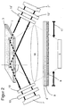
- the device of Figure 1 is with two light sources 7, 7 ', filters 19, 19' and polarizers 18, 18 'shown.
- the light source 7 's ends Light of a wavelength that differs from the first Light source 7 differs.
- preferably polarized light is used.
- the fluorophores Cy5 and Cy7 are used when different marking substances, which are excited at different wavelengths can be used. Examples of this are the fluorophores Cy5 and Cy7. This is a suggestion of the fluorophore Cy5 is a laser diode with a Light with a wavelength between 635 and 655 nm and for the fluorophores Cy7 a laser diode, the light with a wavelength between 730 and 780 nm, used.
- the measurement is carried out in this embodiment in the Way that the diodes 7, 7 'either alternate switched or synchronized accordingly, for example Choppers are used so that secured is that only light from a light source 7 or 7 'can come to the sample for excitation and thereby no falsifications occur.
- A is used for the reference measurement
- Reference antibody that is not made up of an antigen the sample is used.
- the reference antibody is quantified in advance and with a different Marking substance from the one to be determined analyte-specific antibody Ak made distinguishable.
- the amount of the surface actually bound reference antibody can with a second Light source 7 ', the light of a fluorescence of the different Marker substance, one second scattered light filter 8 'and the detector 5 are determined become. With this determination, the losses those that are not bound to the surface analyte-specific antibodies Ak or antigens Ag be taken into account.
- FIG. 3 shows how a sample container 10 for opening 9 in the cover plate 3 of a device is arranged according to Figure 1 and so a connection between sample container 10 via opening 9 to the receiving area 2 can be produced.
- the sample container 10 forms the sample container 10 the container in which the known Quantity marked with the fluorophore marker Biocomponent in the sample to be determined be mixed.
- the sample container 10 clearly define the sample volume and so with a fixed and known sample volume a quantitative one Obtained information about the antigen concentration can be.
- the sample container 10 must therefore always filled with the same amount to be reproducible Get results. Should be cheap he is always filled to the maximum.
- some feasible assay formats is the specific Biocomponent each on the surface of the Sample container 10 and by contact with the liquid sample detaches from the surface and gets into the sample.
- the Biocomponents on additional solid phases in the sample container 10 are located.
- a simple and already known method is to lyophilized antibodies on the surface of the sample container 10 applied. This makes it possible to make the whole thing relative long before the actual execution of the Store immunoassays.
- the recording area 2 defines the surface on the base plate 1, on the depending on the assay format, the corresponding chemical or immobilized biochemical substances become.
- FIG. 4 also shows a preferably cylindrical one Hollow body 12 in which a piston 13 or another suitable cover is shown, which together serve as a pump. Becomes the piston 13 from the cylindrical hollow body 12 moved out, creates a negative pressure, the sample material from the sample container 10 through the receiving area 2 towards the cylindrical hollow body 12 sucks. By capillary forces in the receiving area 2 and the flow becomes through an absorbent fleece maintained until the entire sample volume is through the recording area 2 has been promoted.
- the cylindrical one Hollow body 12 is attached or has a hole in the floor so that it connects to the recording area 2 is present. This can be done through the second Opening 11 as a connection option in the cover plate 3 can be realized. If no cover plate 3 is used, the connection option can also be designed differently his.
- an external other can also be connected to the opening 11 Pump can be connected.
- the essential part of the invention Device can be designed very variable.
- the various elements (plates, Layers) from one kit in different Configurations put together and accordingly for different assay formats as required on site Will be provided.
- Figure 5 shows an example of an inventive Device in which additional functional layers is shown with lateral flow.
- additional functional layers is shown with lateral flow.
- These breakthroughs serve that a connection between the inlet opening 9, the functional layers 26, 27, the receiving area 2 and the drain opening 11 becomes possible.
- the direction of flow give those shown in Figure 5 Arrows again.
- An adaptation to different assay formats can by varying the arrangement and / or selection of functional layers 26, 27 can be achieved. So for example, the functional layers 26 and 27 Reagent reservoir or a pure reaction layer his.
- the structure of part of a shown in FIG device according to the invention differs from the example shown in Figure 5 in that a transverse flow can be achieved.
- functional layers 28, 28 'and 29 is in this Example of the spacer 4 with the cuvette-shaped Receiving area 2 arranged below the cover plate 3.
- FIG Arrows indicate the direction of flow.
- Deviating from the structure shown in FIG. 6, can of course also other arrangements, which ensure a transversal flow become.
- the functional layers, as already mentioned, in number, arrangement and function selection can be varied. The order can also opposite to the example shown be carried out above the spacer 4.
- Separating layers can also be used in this example , but it should be noted that a transverse flow must not be hindered.
- the functional layers can in turn be used as a reagent reservoir serve or reaction layer.
- Layers have the advantage that a complete integrated measuring system and only the Sample must be passed through the setup.
- the functional layers 26, 27, 28, 28 'and 29 the tasks of sample preparation (buffering, Filtration, separation, elimination of interference etc.), as a reagent carrier layer (e.g. for conjugate release) or as a reaction layer (e.g. for Derivatization, for the immobilization of biocomponents or for chemical and / or immunochemical processes Reactions) can be used.
- a reagent carrier layer e.g. for conjugate release
- a reaction layer e.g. for Derivatization, for the immobilization of biocomponents or for chemical and / or immunochemical processes Reactions
- Reagent carrier layer - paper can also be used for this made of 100% cellulose or activated nylon 66, whereby the surfaces can be activated or modified, to change the flow properties (commercial from Pall Biosupport under the Trade name "Prodyne or ACCUWIK membrane” available) or especially for lateral flow systems Polyester carrier with modified surface, where the flow properties are controllable become.
- Reaction layers - as a so-called nitroflow membrane Made of nitrocellulose, PVDF (polyvinyl difluoride) membrane (Commercially available from Millipor with trade names "Immobilon”), whereby here too the surfaces can be modified.
- PVDF polyvinyl difluoride
- fibrous materials cellulose, nitrocellulose, Polypropylene, polycarbonate, polyvinyl difluoride, Hydrogels (e.g. dextran, acrylamide, agar-agar, Carrageenan, alginic acid), polyelectrolytes (e.g. acrylic acid, poly-L-lysine, poly-L-glutamic acid) or core track or glass fiber membranes can be used.
- Hydrogels e.g. dextran, acrylamide, agar-agar, Carrageenan, alginic acid
- polyelectrolytes e.g. acrylic acid, poly-L-lysine, poly-L-glutamic acid
- core track or glass fiber membranes can be used.
- FIGS. 7 and 8 Basic options are shown in FIGS. 7 and 8 shown for the evaluation of the measurement signals.
- the intensity of the measured is in FIG Fluorescence signals are shown as a function of time. With the linear increase in the intensity of the fluorescence signal it is sufficient to increase the signal by differentiation to determine since the increase with time Change in the amount of fluorophore with the invention Device can be measured, correlated. As a result, the measuring time can be kept very short, since the increase in fluorescence intensity is only about must be determined for a short period of time, regardless whether this is at the beginning or later, when carrying out the chemical or biochemical Assay's done. It's just the saturation range to be observed and taken into account that measurements are only taken in a time range in which a temporal change in the fluorescence intensity signal is detectable.
- the difference between an initial and final value is formed and used for evaluation.
- a basic signal S 1 is recorded before the addition of the analyte to be determined at time t 1 and, following the addition of analyte, a final value S 2 of the measured fluorescence intensity is determined at a predeterminable time t 2 .
- the analyte concentration can then be determined by the difference between the values S 2 and S 1 .
- the difference between the times t 2 and t 1 must be so great that an equilibrium has developed.
- FIG. 9 shows a sandwich assay format that practically only for high molecular compounds (proteins, etc.) is suitable.
- This sandwich format can in principle in one Device as shown in FIG. 5 or FIG. 6 is shown, at least a functional layer is to be used.
- the analyte should be labeled with the antibody first incubated and then for evanescent field stimulation and corresponding fluorescence in the detection area the bottom plate 3 are passed.
- Another way of performing a sandwich assay format in sequential form so carried out that first the analyte and then the labeled Antibodies gradually form the sandwich.
- the coating of the base plate area for evanescent field excitation with protein A / G, avidin, etc. also offers the possibility of a universal Element (for various analytes).
- Pre-incubation is a particularly advantageous embodiment of the analyte with a biotinylated (Catcher) antibody and a fluorescent label (Detector) antibodies.
- the two antibodies can for example, simultaneously or sequentially functionalized layers are released.
- the entire immune complex is then connected to one with avidin (alternatively streptavidin or neutravidin) - coated sensor surface bound. decisive is very high for signal formation Affinity between biotin and avidin; this leads to an improvement in the sensitivity of the assay.
- a device according to Figure 2 in connection with two different marking substances be used and so the concentration determination for two different analytes quasi-simultaneously also independent of the respective Connection points are carried out in the reception area, so that the connection of the marked biocomponents does not have to be locally selective.
- an assay format can also be carried out where an antibody and a labeled antibody fragment (e.g. an Fc part or a ScFv fragment) are incubated simultaneously with the analyte, such as this is shown in Figure 10. Only that binds there complete antibodies (on protein A / G or after biotinylation Avidin), this eliminates the need an incubation.
- This format exists the basic possibility, the structure used to regenerate. But this is with avidin / biotin not possible.
- a catcher antibody can also use other biocomponents that bind the analyte immobilized (e.g. protein A / G in the case a sandwich assay for the determination of antibodies).
- biocomponents that bind the analyte immobilized (e.g. protein A / G in the case a sandwich assay for the determination of antibodies).
- One or more components of immunochemical Reaction can also occur on functional layers be provided, such as for conjugate release is the case.
- FIG. 11 shows options for titration / competition formats shown, which are among themselves by sequential or simultaneous incubation distinguish between the immune components. This Both assay formats are particularly suitable for the Determination of low molecular weight compounds that do not Can train sandwich.
- the assay formats shown in Figure 11 also have no directly proportional relationship between the analyte concentration and the intensity of the measured Fluorescence signal. So there is an opposite proportional relationship.
- FIG. 11 can be designed in this way be that a labeled analyte, e.g. Likewise can be contained in this layer.
- the lower one Representation of Figure 11 can be performed that a labeled analyte, for example, in the functional Layer 26 and an antibody in Layer 27 of the example shown in Figure 5 included are.
- the implementation of the example below, which is in Figure 11 is shown, but can also be carried out be that an antibody in the functional Layer 26 and the labeled analyte in the layer 27, in the example shown in FIG. 5, are included.
- all components can be in solution be incubated.
- the assay format shown in Figure 12 sees a pre-incubation of the reactants and the Formation of a bond balance before.
- free analyte competes with the labeled analyte to bind to the antibody, being on the bottom plate 3 the same antibody in the detection area is immobilized, which is also included in the solution is.
- Immobilization can, as with sandwich assay formats be performed.
- the immobilized biocomponent serves exclusively enrichment of the hapten-fluorophore conjugate and can thus be immobilized in excess his.
- immobilizing a specific antibody can be a corresponding structure of the invention
- the device only for one Analytes are used.
- the assay format shown in Figure 12 can be with a Device as shown in Figure 5 be carried out when in the functional Layer 26 is a labeled analyte and in the functional Layer 27 antibodies are included.
- a labeled analyte analogue which a significantly reduced affinity for the antibody has a displacement assay already described be performed. This is in the Figure 13 shown.
- a marked analyte or an analyte analogue for example in the functional Layer 28 of the example shown in FIG. 6 can be included.
- an additional solid phase can also be used be either in a separate reaction space or directly as a functional layer the detection area of the base plate 3 can be.
- the additional fixed phase can in principle be the perform the same functions as the functional ones Layers.
- a separate reaction space e.g. an incubation tube
- an incubation tube such as the Sample container 10 shown in Figures 3 and 4
- generic, i.e. structures that can be used for all analytes can be used.
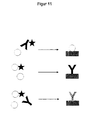
- one of the Immune components (the labeled antibody or labeled Analyte) retained on a solid phase is, for example with a functional layer Hapten-protein conjugate. It only happens when you are present part of the labeled components of free analytes is not bound to the solid phase and can then above the base plate 3 in the detection area be measured. This fact is schematically in the example shown in FIG shown.
- the solid phase is only from antibodies that previously bound to analyte happens like this in the bottom Part of Figure 14 is shown.
- analyte-bound antibodies for example can be detected by a generic anti-antibody.
- a membrane is used as additional solid phase used in the construction is integrated, for example the functional Layer 26 (reservoir for the labeled antibody) and the solid phase as layer 27, the in the example shown in Figure 5, in which in the figure 14 example shown can be used.
- Membranes can contain nitrocellulose, immunodyne, conjugate release membranes, regenerated cellulose, e.g. his.
- the respective biocomponent can Adsorption, covalent binding or by affinity binding be immobilized.
- Haptens can be used as a hapten-protein conjugate be immobilized.
- the wall of a possible usable vessel the for example the wall of the sample container mentioned 10 or the feed lines can also be used as serve solid phase and for example polystyrene vessels or glass capillaries.
- Particle suspensions in which the sample has a suspension solid particles (magnetic particles, latex, etc.) can. These particles can then be created by applying a Magnetic field or separated by filtration afterwards become.
- FIG An example of a displacement assay is shown in FIG with an additional fixed phase in principle shown.
- the solid phase can either be the one mentioned Sample container 10, a feed line or a be functional layer.
- the solid phase can be the functional phase, for example Layer 26, in the example according to FIG. 5.
- the highlighted Antibodies on the base plate 3 in the detection area from a generic anti-antibody or protein A / G, avidin etc. bound.
- the displacement can also be done directly in the detection area on the base plate 3 as a very simple assay configuration be carried out because only a sample is passed through the element.
- the sample can be conditioned by Integration of appropriate functional layers be achieved.
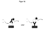
- Possibilities there are two different ones Possibilities, the analyte or the specific Immobilize antibodies as shown in Figure 16 is shown.
- the absolute value of the increase in the fluorescence intensity signal however, the analyte concentration is direct proportional and can be described in the Form are evaluated.
- Figure 17 serves as a general legend for the in 9 to 16 different assay formats shown.
Landscapes
- Health & Medical Sciences (AREA)
- Immunology (AREA)
- Life Sciences & Earth Sciences (AREA)
- Chemical & Material Sciences (AREA)
- Physics & Mathematics (AREA)
- Analytical Chemistry (AREA)
- Biochemistry (AREA)
- General Health & Medical Sciences (AREA)
- General Physics & Mathematics (AREA)
- Pathology (AREA)
- Engineering & Computer Science (AREA)
- Hematology (AREA)
- Urology & Nephrology (AREA)
- Nuclear Medicine, Radiotherapy & Molecular Imaging (AREA)
- Biomedical Technology (AREA)
- Molecular Biology (AREA)
- Optics & Photonics (AREA)
- Cell Biology (AREA)
- Microbiology (AREA)
- Biotechnology (AREA)
- Chemical Kinetics & Catalysis (AREA)
- Food Science & Technology (AREA)
- Medicinal Chemistry (AREA)
- Investigating, Analyzing Materials By Fluorescence Or Luminescence (AREA)
- Investigating Or Analysing Materials By The Use Of Chemical Reactions (AREA)
- Luminescent Compositions (AREA)
- Optical Measuring Cells (AREA)
Claims (16)
- Dispositif pour effectuer des analyses immunologiques par fluorescence en excitant un champ évanescent, dans lequel est disposée au moins une source lumineuse (7, 7') émettant une lumière quasiment monochromatique, orientant des rayons lumineux présentant une longueur d'onde entraínant la fluorescence d'un marqueur lié à un agent chimique ou biochimique d'un complexe récepteur-ligand général, selon un angle α déterminé en fonction d'une profondeur de pénétration d pouvant être prédéfinie pour le champ évanescent, sur une surface limite entre une plaque inférieure (1) transparente d'un point de vue optique, réalisée dans un matériau dont l'indice de réfraction n1 est supérieur à l'indice de réfraction n2 du matériau se trouvant au-dessus de la surface limite, et une zone de réception conçue en forme de cuvette (2), destinée à l'échantillon,
la zone de réception (2), du côté opposé à la plaque inférieure (1), est revêtue d'une plaque de recouvrement (3), moyennant quoi, entre la plaque inférieure (1) et la plaque de recouvrement (3) ou une zone d'admission permettant à l'échantillon d'atteindre la zone de réception (2), est disposée au moins une couche fonctionnelle (26, 27, 28, 28') faisant l'objet d'un passage latéral ou transversal sous l'effet d'une force d'aspiration, de pression, ou capillaire, pour préparer les échantillons, et
un détecteur (5) destiné à enregistrer la lumière fluorescente est disposé en même temps que la source lumineuse par rapport à la plaque inférieure (1). - Dispositif selon la revendication 1, caractérisé en ce que, entre la plaque inférieure (1) et la plaque de recouvrement (3) est disposé un séparateur (4) donnant à la zone de réception une forme de cuvette (2).
- Dispositif selon la revendication 1 ou 2, caractérisé en ce que, dans la plaque de recouvrement (3), il existe un orifice d'admission et un orifice d'évacuation (9, 11).
- Dispositif selon l'une quelconque des revendications 1 à 3, caractérisé en ce que la ou les couche(s) fonctionnelle(s) (26, 27, 28, 28', 29) est (sont) constituée(s) de matières fibreuses, cellulose, nitrocellulose, polypropylène, polycarbonate, difluorure de polyvinyle ou d'un hydrogel ou de polyélectrolytes ou de membranes de traces nucléaires ou de fibres de verre, ou sont conçues sous la forme d'une colonne compacte.
- Dispositif selon l'une quelconque des revendications 1 à 4, caractérisé en ce qu'au moins une couche fonctionnelle (29) dans la zone de réception (2) est en contact direct avec la plaque inférieure (1).
- Dispositif selon l'une quelconque des revendications 1 à 5, caractérisé en ce que plusieurs couches fonctionnelles (26, 27) séparées par des couches de séparation (25, 25') sont disposées alternativement les unes au-dessus des autres en permettant de relier l'orifice d'admission et l'orifice d'évacuation (9, 11) par l'intermédiaire de la zone de réception (2) à l'aide de perforations.
- Dispositif selon la revendication 5, caractérisé en ce qu'au moins deux couches ayant des fonctions différentes sont disposées à un même niveau en étant adjacentes l'une à l'autre.
- Dispositif selon l'une quelconque des revendications 1 à 5, caractérisé en ce que plusieurs couches fonctionnelles (28, 28', 29) sont disposées directement les unes au-dessus des autres.
- Dispositif selon l'une quelconque des revendications 1 à 8, caractérisé en ce qu'un conteneur d'échantillons (10) déterminant un volume d'échantillons défini est disposé de telle sorte qu'il se forme une liaison entre la zone de réception en forme de cuvette (2) et le conteneur d'échantillons (10).
- Dispositif selon l'une quelconque des revendications 1 à 9, caractérisé en ce qu'une phase solide est formée dans le conteneur d'échantillons (10), dans un canal d'admission, dans la zone de réception (2) ou une couche fonctionnelle en tant que telle est formée.
- Procédé pour effectuer des analyses immunologiques par fluorescence en excitant un champ évanescent, dans lequel un volume d'échantillons est acheminé par l'effet d'aspiration, de pression ou des forces capillaires pour préparer l'échantillon, au travers d'une ou plusieurs couches fonctionnelles (26, 27, 28, 28', 29) puis au travers de la zone de réception en forme de cuvette (2), qui est lié à des composants chimiques ou biochimiques marqués à déterminer en fonction du dosage biochimique, au niveau de la surface dans la zone de réception (2), et la lumière fluorescente est mesurée par rapport au temps à l'aide d'un détecteur (5) en excitant le champ évanescent.
- Procédé selon la revendication 11, caractérisé en ce que, à l'aide de la ou des couche(s) fonctionnelle(s) (26, 27, 28, 28', 29), on réalise un filtrage, une séparation, une élimination des substances interférentes, la libération des réactifs ou des réactions chimiques.
- Procédé selon la revendication 11 ou 12, caractérisé en ce que l'augmentation de l'intensité de la lumière fluorescente mesurée est utilisée pour mesurer la concentration en analytes.
- Procédé selon la revendication 11 ou 12, caractérisé en ce que la différence entre deux signaux d'intensité de fluorescence (S1 et S2) mesurés à des distances pouvant être prédéfinies est utilisée pour déterminer la concentration en analytes.
- Procédé selon l'une quelconque des revendications 11 à 14, caractérisé en ce qu'on réalise des dosages biochimiques de complexes récepteur-ligand généraux, comme les complexes anticorps-antigène, lectine-hydrate de carbone, acide nucléique complémentaire d'ADN ou d'ARN, protéines d'ADN ou d'ARN, récepteur hormonal, cofacteurs enzyme-enzyme, protéine G ou protéine A-immunoglobine, ou avidine-biotine.
- Procédé selon l'une quelconque des revendications 11 à 15, caractérisé en ce qu'on réalise des dosages « sandwich », de titrage, des dosages avec compétition et/ou déplacement.
Applications Claiming Priority (3)
| Application Number | Priority Date | Filing Date | Title |
|---|---|---|---|
| DE19711281A DE19711281C1 (de) | 1997-03-18 | 1997-03-18 | Vorrichtung und Verfahren zur Durchführung von Fluoreszenzimmunotests |
| DE19711281 | 1997-03-18 | ||
| PCT/DE1998/000729 WO1998041843A2 (fr) | 1997-03-18 | 1998-03-11 | Dispositif et methode pour effectuer des analyses immunologiques par fluorescence |
Publications (2)
| Publication Number | Publication Date |
|---|---|
| EP0968412A2 EP0968412A2 (fr) | 2000-01-05 |
| EP0968412B1 true EP0968412B1 (fr) | 2002-11-06 |
Family
ID=7823792
Family Applications (1)
| Application Number | Title | Priority Date | Filing Date |
|---|---|---|---|
| EP98923995A Expired - Lifetime EP0968412B1 (fr) | 1997-03-18 | 1998-03-11 | Dispositif et methode pour effectuer des analyses immunologiques par fluorescence |
Country Status (8)
| Country | Link |
|---|---|
| EP (1) | EP0968412B1 (fr) |
| JP (1) | JP2001515592A (fr) |
| AT (1) | ATE227425T1 (fr) |
| CA (1) | CA2283251C (fr) |
| DE (2) | DE19711281C1 (fr) |
| DK (1) | DK0968412T3 (fr) |
| RU (1) | RU2194972C2 (fr) |
| WO (1) | WO1998041843A2 (fr) |
Families Citing this family (12)
| Publication number | Priority date | Publication date | Assignee | Title |
|---|---|---|---|---|
| DE19933458B4 (de) * | 1999-07-15 | 2015-08-20 | Eppendorf Ag | Einrichtungen und Systeme zum Handhaben von Flüssigkeitsproben |
| DE10001116C2 (de) * | 2000-01-13 | 2002-11-28 | Meinhard Knoll | Vorrichtung und Verfahren zur optischen oder elektrochemischen quantitativen Bestimmung chemischer oder biochemischer Substanzen in flüssigen Proben |
| DE10058095C2 (de) * | 2000-11-03 | 2003-12-18 | Fraunhofer Ges Forschung | Vorrichtung zur Bestimmung von Analyten durch Chemilumineszenz |
| DE10105711B4 (de) * | 2001-02-08 | 2005-03-10 | Ibidi Gmbh | Probenträger für chemische und biologische Proben |
| DE10307802A1 (de) * | 2003-02-24 | 2004-09-09 | Advalytix Ag | Analyseverfahren und -Vorrichtung zur Analyse von spezifischen Bindungsreaktionen |
| DE102004022263A1 (de) * | 2004-05-06 | 2005-12-15 | Clondiag Chip Technologies Gmbh | Vorrichtung und Verfahren zum Nachweis von molekularen Wechselwirkungen |
| RU2280247C1 (ru) * | 2005-06-30 | 2006-07-20 | Общество с ограниченной ответственностью "Биочип-Аналитика" (ООО "Биочип-Аналитика") | Биочип для флуоресцентного и люминесцентного анализа |
| JP2008032420A (ja) * | 2006-07-26 | 2008-02-14 | National Institute Of Advanced Industrial & Technology | エバネッセント励起蛍光観察における背景蛍光を減弱する方法及び部材 |
| DE102007019695B4 (de) * | 2007-04-24 | 2009-08-13 | Analytik Jena Ag | Küvette für die optische Analyse kleiner Volumina |
| DE102010038431A1 (de) | 2010-07-26 | 2012-01-26 | Diasys Diagnostic Systems Gmbh | Messkassette und Messvorrichtung für die Detektion von Zielmolekülen in einer flüssigen Probe durch Messung von Fluoreszenzemission nach Anregung im evaneszenten Feld |
| US11346839B2 (en) | 2018-08-03 | 2022-05-31 | Insingulo Ab | Method for determining the interaction between a ligand and a receptor |
| DE102022207704A1 (de) | 2022-07-27 | 2024-02-01 | Robert Bosch Gesellschaft mit beschränkter Haftung | Verteilereinheit für ein Analysegerät zum Analysieren einer in einer Mikrofluidikkartusche enthaltenen Probe, Analysegerät sowie Verfahren zum Herstellen einer Korpuseinheit für eine Verteilereinheit |
Family Cites Families (8)
| Publication number | Priority date | Publication date | Assignee | Title |
|---|---|---|---|---|
| DE3814370A1 (de) * | 1988-04-28 | 1989-11-09 | Boehringer Mannheim Gmbh | Testtraeger fuer die analyse einer probenfluessigkeit, verfahren zur durchfuehrung einer solchen analyse und herstellungsverfahren |
| SE462408B (sv) * | 1988-11-10 | 1990-06-18 | Pharmacia Ab | Optiskt biosensorsystem utnyttjande ytplasmonresonans foer detektering av en specific biomolekyl, saett att kalibrera sensoranordningen samt saett att korrigera foer baslinjedrift i systemet |
| GB8827853D0 (en) * | 1988-11-29 | 1988-12-29 | Ares Serono Res & Dev Ltd | Sensor for optical assay |
| DE4121493A1 (de) * | 1991-06-28 | 1993-01-07 | Draegerwerk Ag | Analysevorrichtung zur quantitativen, immunologischen bestimmung von schadstoffen |
| RU2039986C1 (ru) * | 1992-03-23 | 1995-07-20 | Институт иммунобиотехнологии | Способ конкурентного иммунофлуоресцентного определения антигенов |
| CA2162996C (fr) * | 1993-05-18 | 2008-02-05 | James N. Herron | Appareil et methodes pour fluoro-immuno-essais homogenes multi-analysats |
| DE19611025A1 (de) * | 1996-03-20 | 1997-09-25 | Inst Chemo Biosensorik | Optischer Lichtwellenleitersensor auf der Basis der resonanten optischen Anregung von Oberflächenplasmawellen |
| DE19628002C1 (de) * | 1996-07-11 | 1997-12-18 | Inst Chemo Biosensorik | Vorrichtung und Verfahren zur Durchführung von Fluoreszenzimmunotests |
-
1997
- 1997-03-18 DE DE19711281A patent/DE19711281C1/de not_active Expired - Fee Related
-
1998
- 1998-03-11 JP JP54002398A patent/JP2001515592A/ja active Pending
- 1998-03-11 CA CA002283251A patent/CA2283251C/fr not_active Expired - Fee Related
- 1998-03-11 DE DE59806188T patent/DE59806188D1/de not_active Expired - Fee Related
- 1998-03-11 DK DK98923995T patent/DK0968412T3/da active
- 1998-03-11 WO PCT/DE1998/000729 patent/WO1998041843A2/fr not_active Ceased
- 1998-03-11 AT AT98923995T patent/ATE227425T1/de active
- 1998-03-11 EP EP98923995A patent/EP0968412B1/fr not_active Expired - Lifetime
- 1998-03-11 RU RU99121646/28A patent/RU2194972C2/ru not_active IP Right Cessation
Also Published As
| Publication number | Publication date |
|---|---|
| WO1998041843A2 (fr) | 1998-09-24 |
| DE19711281C1 (de) | 1998-04-16 |
| CA2283251A1 (fr) | 1998-09-24 |
| JP2001515592A (ja) | 2001-09-18 |
| DK0968412T3 (da) | 2003-03-10 |
| ATE227425T1 (de) | 2002-11-15 |
| CA2283251C (fr) | 2007-11-27 |
| RU2194972C2 (ru) | 2002-12-20 |
| EP0968412A2 (fr) | 2000-01-05 |
| WO1998041843A3 (fr) | 1998-11-19 |
| DE59806188D1 (de) | 2002-12-12 |
Similar Documents
| Publication | Publication Date | Title |
|---|---|---|
| EP0910792B1 (fr) | Procede et dispositif pour mettre en oeuvre des tests quantitatifs d'affinite a fluorescence | |
| US6686208B2 (en) | Device and method for carrying out fluoresence immunotests | |
| DE69333050T2 (de) | Anordnung zur probenbestimmung | |
| EP1556695B1 (fr) | Plate-forme analytique et procede d'identification par des analytes a deceler dans un echantillon eventuellement apres fractionnement et se presentant sous forme de partenaires de liaison specifiques | |
| EP1274986B1 (fr) | Dispositif et procede de determination de plusieurs substances a analyser | |
| DE69412137T2 (de) | Sensoreinrichtung zum sandwichtest | |
| EP0988526B1 (fr) | Dispositif de detection de substances chimiques et biochimiques par excitation de lumiere fluorescente et son procede de production | |
| DE60037268T2 (de) | Verfahren zur durchführung magnetischer chromatographischer assays | |
| US20030148542A1 (en) | Kit and method for determining a plurality of analytes | |
| DE3786278T2 (de) | Element zum Immunoassay und Verfahren zu seiner Benutzung. | |
| EP0968412B1 (fr) | Dispositif et methode pour effectuer des analyses immunologiques par fluorescence | |
| DE60016779T2 (de) | Assay-vorrichtung | |
| EP1334361A2 (fr) | Kit et procede permettant la detection d'analytes multiples avec des mesures permettant la referenciation de la densite d'elements de reconnaissance immobilises | |
| EP1916524A1 (fr) | Elément d'essai rotatif | |
| DE102008045070A1 (de) | Testvorrichtung mit gemeinsamen Zonen | |
| DE10001116C2 (de) | Vorrichtung und Verfahren zur optischen oder elektrochemischen quantitativen Bestimmung chemischer oder biochemischer Substanzen in flüssigen Proben | |
| EP2194381B1 (fr) | Elément de test doté d'une zone de contrôle et de calibrage combinée | |
| WO2003096018A2 (fr) | Trousse de mise au point de dosage et d'analyses en serie | |
| WO2002046756A1 (fr) | Kit et procede de detection d'analytes multiples comprenant des mesures de referenciation a resolution locale d'une intensite de lumiere d'excitation | |
| EP1561109A1 (fr) | Plate-forme analytique et procede d'identification avec des substances d'analyse a identifier dans un echantillon, se presentant sous forme de partenaires de liaison specifiques immobilises | |
| DE60309317T2 (de) | Biomolekulares kinetik-messverfahren mit hilfe von einem durchfluss-mikroarray | |
| EP1531331B1 (fr) | Procédé de détermination de l'hémoglobine glycosylée à l'aide d'une couche d'extraction | |
| DE69732034T2 (de) | Assay-verfahren | |
| DE69129035T2 (de) | Testverfahren | |
| DE69818706T2 (de) | Analytisches verfahren mit teilchen und testkit um das verfahren durchzuführen |
Legal Events
| Date | Code | Title | Description |
|---|---|---|---|
| PUAI | Public reference made under article 153(3) epc to a published international application that has entered the european phase |
Free format text: ORIGINAL CODE: 0009012 |
|
| 17P | Request for examination filed |
Effective date: 19990908 |
|
| AK | Designated contracting states |
Kind code of ref document: A2 Designated state(s): AT BE CH DE DK ES FI FR GB GR IE IT LI NL SE |
|
| RIN1 | Information on inventor provided before grant (corrected) |
Inventor name: KATERKAMP, ANDREAS Inventor name: TRAU, DIETER Inventor name: MEUSEL, MARKUS |
|
| 17Q | First examination report despatched |
Effective date: 20010510 |
|
| GRAG | Despatch of communication of intention to grant |
Free format text: ORIGINAL CODE: EPIDOS AGRA |
|
| GRAG | Despatch of communication of intention to grant |
Free format text: ORIGINAL CODE: EPIDOS AGRA |
|
| GRAG | Despatch of communication of intention to grant |
Free format text: ORIGINAL CODE: EPIDOS AGRA |
|
| GRAH | Despatch of communication of intention to grant a patent |
Free format text: ORIGINAL CODE: EPIDOS IGRA |
|
| GRAH | Despatch of communication of intention to grant a patent |
Free format text: ORIGINAL CODE: EPIDOS IGRA |
|
| GRAA | (expected) grant |
Free format text: ORIGINAL CODE: 0009210 |
|
| AK | Designated contracting states |
Kind code of ref document: B1 Designated state(s): AT BE CH DE DK ES FI FR GB GR IE IT LI NL SE |
|
| PG25 | Lapsed in a contracting state [announced via postgrant information from national office to epo] |
Ref country code: IT Free format text: LAPSE BECAUSE OF FAILURE TO SUBMIT A TRANSLATION OF THE DESCRIPTION OR TO PAY THE FEE WITHIN THE PRE;WARNING: LAPSES OF ITALIAN PATENTS WITH EFFECTIVE DATE BEFORE 2007 MAY HAVE OCCURRED AT ANY TIME BEFORE 2007. THE CORRECT EFFECTIVE DATE MAY BE DIFFERENT FROM THE ONE RECORDED.SCRIBED TIME-LIMIT Effective date: 20021106 Ref country code: IE Free format text: LAPSE BECAUSE OF FAILURE TO SUBMIT A TRANSLATION OF THE DESCRIPTION OR TO PAY THE FEE WITHIN THE PRESCRIBED TIME-LIMIT Effective date: 20021106 Ref country code: GR Free format text: LAPSE BECAUSE OF FAILURE TO SUBMIT A TRANSLATION OF THE DESCRIPTION OR TO PAY THE FEE WITHIN THE PRESCRIBED TIME-LIMIT Effective date: 20021106 |
|
| REF | Corresponds to: |
Ref document number: 227425 Country of ref document: AT Date of ref document: 20021115 Kind code of ref document: T |
|
| REG | Reference to a national code |
Ref country code: GB Ref legal event code: FG4D Free format text: NOT ENGLISH |
|
| REG | Reference to a national code |
Ref country code: CH Ref legal event code: EP |
|
| REG | Reference to a national code |
Ref country code: IE Ref legal event code: FG4D Free format text: GERMAN |
|
| REF | Corresponds to: |
Ref document number: 59806188 Country of ref document: DE Date of ref document: 20021212 |
|
| REG | Reference to a national code |
Ref country code: CH Ref legal event code: NV Representative=s name: TROESCH SCHEIDEGGER WERNER AG |
|
| REG | Reference to a national code |
Ref country code: DK Ref legal event code: T3 |
|
| GBT | Gb: translation of ep patent filed (gb section 77(6)(a)/1977) |
Effective date: 20030227 |
|
| PG25 | Lapsed in a contracting state [announced via postgrant information from national office to epo] |
Ref country code: ES Free format text: LAPSE BECAUSE OF FAILURE TO SUBMIT A TRANSLATION OF THE DESCRIPTION OR TO PAY THE FEE WITHIN THE PRESCRIBED TIME-LIMIT Effective date: 20030529 |
|
| ET | Fr: translation filed | ||
| REG | Reference to a national code |
Ref country code: IE Ref legal event code: FD4D Ref document number: 0968412E Country of ref document: IE |
|
| PLBE | No opposition filed within time limit |
Free format text: ORIGINAL CODE: 0009261 |
|
| STAA | Information on the status of an ep patent application or granted ep patent |
Free format text: STATUS: NO OPPOSITION FILED WITHIN TIME LIMIT |
|
| PG25 | Lapsed in a contracting state [announced via postgrant information from national office to epo] |
Ref country code: DE Free format text: LAPSE BECAUSE OF NON-PAYMENT OF DUE FEES Effective date: 20031001 |
|
| 26N | No opposition filed |
Effective date: 20030807 |
|
| PGFP | Annual fee paid to national office [announced via postgrant information from national office to epo] |
Ref country code: BE Payment date: 20050228 Year of fee payment: 8 Ref country code: NL Payment date: 20050228 Year of fee payment: 8 |
|
| PGFP | Annual fee paid to national office [announced via postgrant information from national office to epo] |
Ref country code: DK Payment date: 20050314 Year of fee payment: 8 |
|
| PGFP | Annual fee paid to national office [announced via postgrant information from national office to epo] |
Ref country code: FI Payment date: 20050315 Year of fee payment: 8 |
|
| PGFP | Annual fee paid to national office [announced via postgrant information from national office to epo] |
Ref country code: SE Payment date: 20050317 Year of fee payment: 8 |
|
| REG | Reference to a national code |
Ref country code: CH Ref legal event code: PUE Owner name: PES GESELLSCHAFT FUER MEDIZINISCHE DIAGNOSE-SYSTE Free format text: INSTITUT FUR CHEMO- UND BIOSENSORIK MUENSTER E.V.#MENDELSTRASSE 7#48149 MUENSTER (DE) -TRANSFER TO- PES GESELLSCHAFT FUER MEDIZINISCHE DIAGNOSE-SYSTEME MBH#HAUPTSTRASSE 103#04416 LEIPZIG-MARKKLEBERG (DE) Ref country code: CH Ref legal event code: PK |
|
| REG | Reference to a national code |
Ref country code: GB Ref legal event code: 732E |
|
| NLS | Nl: assignments of ep-patents |
Owner name: PES GESELLSCHAFT FUER MEDIZINISCHE DIAGNOSE-SYSTEM Effective date: 20050901 |
|
| PG25 | Lapsed in a contracting state [announced via postgrant information from national office to epo] |
Ref country code: FI Free format text: LAPSE BECAUSE OF NON-PAYMENT OF DUE FEES Effective date: 20060311 |
|
| PG25 | Lapsed in a contracting state [announced via postgrant information from national office to epo] |
Ref country code: SE Free format text: LAPSE BECAUSE OF NON-PAYMENT OF DUE FEES Effective date: 20060312 |
|
| PG25 | Lapsed in a contracting state [announced via postgrant information from national office to epo] |
Ref country code: DK Free format text: LAPSE BECAUSE OF NON-PAYMENT OF DUE FEES Effective date: 20060331 Ref country code: BE Free format text: LAPSE BECAUSE OF NON-PAYMENT OF DUE FEES Effective date: 20060331 |
|
| PG25 | Lapsed in a contracting state [announced via postgrant information from national office to epo] |
Ref country code: NL Free format text: LAPSE BECAUSE OF NON-PAYMENT OF DUE FEES Effective date: 20061001 |
|
| REG | Reference to a national code |
Ref country code: DK Ref legal event code: EBP |
|
| EUG | Se: european patent has lapsed | ||
| NLV4 | Nl: lapsed or anulled due to non-payment of the annual fee |
Effective date: 20061001 |
|
| BERE | Be: lapsed |
Owner name: G.- FUER MEDIZINISCHE DIAGNOSE-SYSTEME M.B.H. *PES Effective date: 20060331 |
|
| PGFP | Annual fee paid to national office [announced via postgrant information from national office to epo] |
Ref country code: CH Payment date: 20140324 Year of fee payment: 17 |
|
| PGFP | Annual fee paid to national office [announced via postgrant information from national office to epo] |
Ref country code: AT Payment date: 20140325 Year of fee payment: 17 |
|
| PGFP | Annual fee paid to national office [announced via postgrant information from national office to epo] |
Ref country code: GB Payment date: 20140324 Year of fee payment: 17 |
|
| PGFP | Annual fee paid to national office [announced via postgrant information from national office to epo] |
Ref country code: FR Payment date: 20140327 Year of fee payment: 17 |
|
| REG | Reference to a national code |
Ref country code: CH Ref legal event code: PL |
|
| REG | Reference to a national code |
Ref country code: AT Ref legal event code: MM01 Ref document number: 227425 Country of ref document: AT Kind code of ref document: T Effective date: 20150311 |
|
| GBPC | Gb: european patent ceased through non-payment of renewal fee |
Effective date: 20150311 |
|
| REG | Reference to a national code |
Ref country code: FR Ref legal event code: ST Effective date: 20151130 |
|
| PG25 | Lapsed in a contracting state [announced via postgrant information from national office to epo] |
Ref country code: CH Free format text: LAPSE BECAUSE OF NON-PAYMENT OF DUE FEES Effective date: 20150331 Ref country code: LI Free format text: LAPSE BECAUSE OF NON-PAYMENT OF DUE FEES Effective date: 20150331 Ref country code: GB Free format text: LAPSE BECAUSE OF NON-PAYMENT OF DUE FEES Effective date: 20150311 |
|
| PG25 | Lapsed in a contracting state [announced via postgrant information from national office to epo] |
Ref country code: FR Free format text: LAPSE BECAUSE OF NON-PAYMENT OF DUE FEES Effective date: 20150331 Ref country code: AT Free format text: LAPSE BECAUSE OF NON-PAYMENT OF DUE FEES Effective date: 20150311 |