EP0968496B1 - Dispositif de selection de micros pour instrument a cordes, et instrument a cordes - Google Patents
Dispositif de selection de micros pour instrument a cordes, et instrument a cordes Download PDFInfo
- Publication number
- EP0968496B1 EP0968496B1 EP98906786A EP98906786A EP0968496B1 EP 0968496 B1 EP0968496 B1 EP 0968496B1 EP 98906786 A EP98906786 A EP 98906786A EP 98906786 A EP98906786 A EP 98906786A EP 0968496 B1 EP0968496 B1 EP 0968496B1
- Authority
- EP
- European Patent Office
- Prior art keywords
- voice signal
- switching apparatus
- sound pickup
- state
- string instrument
- Prior art date
- Legal status (The legal status is an assumption and is not a legal conclusion. Google has not performed a legal analysis and makes no representation as to the accuracy of the status listed.)
- Expired - Lifetime
Links
- 238000000034 method Methods 0.000 claims description 28
- 230000015654 memory Effects 0.000 claims description 14
- 230000006870 function Effects 0.000 claims 1
- 230000003287 optical effect Effects 0.000 description 3
- 238000010586 diagram Methods 0.000 description 2
- 230000000694 effects Effects 0.000 description 2
- 230000015572 biosynthetic process Effects 0.000 description 1
- 239000003990 capacitor Substances 0.000 description 1
- 239000003086 colorant Substances 0.000 description 1
- 239000004020 conductor Substances 0.000 description 1
- 238000010276 construction Methods 0.000 description 1
- 238000005336 cracking Methods 0.000 description 1
- 230000001419 dependent effect Effects 0.000 description 1
- 230000005669 field effect Effects 0.000 description 1
- 239000000463 material Substances 0.000 description 1
- 230000005236 sound signal Effects 0.000 description 1
- 238000003786 synthesis reaction Methods 0.000 description 1
- 208000029257 vision disease Diseases 0.000 description 1
- 230000000007 visual effect Effects 0.000 description 1
- 230000004393 visual impairment Effects 0.000 description 1
Images

Classifications
-
- G—PHYSICS
- G10—MUSICAL INSTRUMENTS; ACOUSTICS
- G10H—ELECTROPHONIC MUSICAL INSTRUMENTS; INSTRUMENTS IN WHICH THE TONES ARE GENERATED BY ELECTROMECHANICAL MEANS OR ELECTRONIC GENERATORS, OR IN WHICH THE TONES ARE SYNTHESISED FROM A DATA STORE
- G10H1/00—Details of electrophonic musical instruments
- G10H1/0008—Associated control or indicating means
-
- G—PHYSICS
- G10—MUSICAL INSTRUMENTS; ACOUSTICS
- G10H—ELECTROPHONIC MUSICAL INSTRUMENTS; INSTRUMENTS IN WHICH THE TONES ARE GENERATED BY ELECTROMECHANICAL MEANS OR ELECTRONIC GENERATORS, OR IN WHICH THE TONES ARE SYNTHESISED FROM A DATA STORE
- G10H1/00—Details of electrophonic musical instruments
- G10H1/18—Selecting circuits
- G10H1/26—Selecting circuits for automatically producing a series of tones
-
- G—PHYSICS
- G10—MUSICAL INSTRUMENTS; ACOUSTICS
- G10H—ELECTROPHONIC MUSICAL INSTRUMENTS; INSTRUMENTS IN WHICH THE TONES ARE GENERATED BY ELECTROMECHANICAL MEANS OR ELECTRONIC GENERATORS, OR IN WHICH THE TONES ARE SYNTHESISED FROM A DATA STORE
- G10H3/00—Instruments in which the tones are generated by electromechanical means
- G10H3/12—Instruments in which the tones are generated by electromechanical means using mechanical resonant generators, e.g. strings or percussive instruments, the tones of which are picked up by electromechanical transducers, the electrical signals being further manipulated or amplified and subsequently converted to sound by a loudspeaker or equivalent instrument
- G10H3/14—Instruments in which the tones are generated by electromechanical means using mechanical resonant generators, e.g. strings or percussive instruments, the tones of which are picked up by electromechanical transducers, the electrical signals being further manipulated or amplified and subsequently converted to sound by a loudspeaker or equivalent instrument using mechanically actuated vibrators with pick-up means
- G10H3/18—Instruments in which the tones are generated by electromechanical means using mechanical resonant generators, e.g. strings or percussive instruments, the tones of which are picked up by electromechanical transducers, the electrical signals being further manipulated or amplified and subsequently converted to sound by a loudspeaker or equivalent instrument using mechanically actuated vibrators with pick-up means using a string, e.g. electric guitar
- G10H3/182—Instruments in which the tones are generated by electromechanical means using mechanical resonant generators, e.g. strings or percussive instruments, the tones of which are picked up by electromechanical transducers, the electrical signals being further manipulated or amplified and subsequently converted to sound by a loudspeaker or equivalent instrument using mechanically actuated vibrators with pick-up means using a string, e.g. electric guitar using two or more pick-up means for each string
-
- G—PHYSICS
- G10—MUSICAL INSTRUMENTS; ACOUSTICS
- G10H—ELECTROPHONIC MUSICAL INSTRUMENTS; INSTRUMENTS IN WHICH THE TONES ARE GENERATED BY ELECTROMECHANICAL MEANS OR ELECTRONIC GENERATORS, OR IN WHICH THE TONES ARE SYNTHESISED FROM A DATA STORE
- G10H2240/00—Data organisation or data communication aspects, specifically adapted for electrophonic musical tools or instruments
- G10H2240/091—Info, i.e. juxtaposition of unrelated auxiliary information or commercial messages with or between music files
Definitions
- the invention relates to a pickup switching device for a stringed instrument, especially an electric one Guitar, according to the preamble of claim 1. Die The invention further relates to a method for setting a pickup switching device for stringed instruments according to the preamble of claim 8. The invention further relates to a stringed instrument with a pickup according to the preamble of claim 11.
- the pickups for stringed instruments usually have either one Coil or then a so-called double coil, which two electrically separated coils arranged on the pickup having.
- a double coil is also called called “humbucker pickup”.
- With electric guitars are usually several pickups in Direction of the strings spaced.
- the best known arrangements are the so called “GIBSON Tonality ", which consists of two pickups with a double coil exists, and the so-called “FENDER tonality”, which consists of three pickups with one coil each.
- WO-92/13335 is a pickup switching device known for an electric guitar which the individual coils of a plurality of pickups in different combinations allowed to connect the electric guitar in different tonality too play.
- This known pickup switching device has the disadvantage that both the number connectable pickup as well as their Possible combinations are very limited.
- US-A-5 399 800 proposes a kind of instruction manual to output acoustically for keyboard instruments by means of speech synthesis.
- the object is achieved in particular with a pickup switching device which comprises an actuatable switching device which is intended to connect the coils of the pickups in different combinations, in order thereby to generate an output signal of different tonality, and which also comprises a speech signal generating device which is dependent on the respective switching state of the switching device generates a speech signal denoting the state.
- a stringed instrument such as a guitar
- the speech signal generating device generating a speech signal which describes the detected state with the aid of speech.
- the speech signal is fed to an electroacoustic transducer, such as a loudspeaker or a headphone, so that the speech signal can be listened to by the instrument player and possibly also by the audience.
- the stringed instrument according to the invention has the advantage on that its states by using a Speech signal are writable so that the Instrument players in a simple and pleasant way the current condition of the stringed instrument becomes.
- An electronic guitar can do a variety have different states, for example the Wiring of the coils, the state of charge of the battery, Setting the volume controller, activated filter etc., their respective state through the voice output can be described. For example, the battery almost discharged, this condition can be compared to the Voice signal "battery low" described and over the Speakers are output.
- the stringed instrument or the Pickup switching device always requires one Speech signal generating device.
- the remaining Components can come in a variety of ways be designed in a simple embodiment as mechanical switch, in a sophisticated Embodiment comprising a microcomputer.
- the switching device can act as a mechanical switch be designed for the coils of the pickups a plurality of predefined Has possible combinations, with a Operate the switch one of the fixed Connections is selected and the individual coils be connected accordingly, the Signal of the coils connected in this way downstream electroacoustic transducers, in particular a speaker.
- the selected switching state of a Speech generating device supplied which a Voice signal generated using the selected state Describes words. This voice signal is preferred fed to the aforementioned speaker, which Speech signal also via an additional electroacoustic transducer, for example via a Headphones or one built into the guitar Speakers can be output.
- the Pickup switching device an electronic Control device on with selectively controllable Switches, each coil can be connected to a switch is.
- the switches are electromechanical, for example comprising an electromagnet and a make contact, or electronically, for example consisting only of a FET transistor, designed.
- the Control device configured and programmable also a plurality of memories with which one connection combination of coils each can be saved.
- one Programming process can be, for example, from a variety possible connections of coils one Connection combination selected and a memory are assigned, the control device or the memory, for example, via an the guitar arranged push button switch can be activated.
- a guitar can have six buttons have, with each key switch Freely programmable connection combination assigned can be.
- An advantage of the invention Device can be seen in that the preferred Any combination of push button switches can be assigned, and that switching between those programmed in this way Connection combinations very quickly by pressing of the respective push button switch can take place.
- Another advantage of the device according to the invention can be seen in the fact that a combination of connections, in particular the current assignment of a key switch, can be queried in a simple manner by means of speech can. Another advantage is that the Voice can be heard on the same speaker, via which the sound signal of the guitar is also output.
- the Programming process also by a voice signal issued, for example, instructions for the required entries or the saved Settings during the programming process appropriately chosen words described and on Speakers are output.
- One advantage of the device according to the invention is that to see that by outputting a speech signal the Operation of the pickup switching device for one Guitarists are simplified because everyone State of the switching device in a simple manner can be queried, and because the preferred combinations of Through the preferred tonalities a programming process in a simple way Push buttons can be assigned.
- An advantage of the invention Pickup switching device can be seen in that the Speakers always needed for an electric guitar can also be used for the output of the speech signal is, so no additional display device, in particular, no visual display is required.
- the acoustic signal also has the advantage that the Guitar in a variety of lighting conditions, even in the dark or with eyes closed is programmable.
- the guitar is also for People with visual impairments such as Operable for the blind.
- Another advantage is that this Programming is done in a very pleasant way, in a first phase a combination of coils is set, with the speech signal each ongoing programming step or the Connection combination calls, and in the second Phase the selected tonality by pressing the Strings can be listened to immediately. If the sound can not have the desired tonality in Programming mode immediately another Connection combinations can be selected, which in turn can be heard by pressing the strings. The Assign the pushbuttons with different ones Connection combinations can therefore very quickly and done pleasantly.
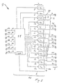
- the electrical circuit diagram shown in Fig. 1 Pickup switching device 1 has a plurality electrical connectors 2, each of the Connecting elements 2a, 2b, 2c, 2d, 2e, 2f, 2g, 2h, 2i, 2j for example as a clamp or as a Plug is designed to be an electrically conductive Connection to the coils 14a, 14b, 15a, 15b, 16a, 17a, 18a, 19a of pickups arranged on the guitar 14,15,16,17,18,19 to effect.
- the connecting element 2j is grounded and the fasteners 2a, 2b, 2c, 2d, 2e, 2f, 2g, 2h, 2i, 2j are about electrical Conductors, which, as shown, also partially with each other are connected to switches 4.
- Switches 4a, 4b, 4c, 4d, 4e, 4f, 4g, 4h, 4i, 4j, 4k, 4l, 4m, 4n as field effect transistors (FET transistors) educated.
- These switches 4a, 4b, 4c, 4d, 4e, 4f, 4g, 4h, 4i, 4j, 4k, 4l, 4m, 4n could also be in a different construction, for example as controllable be designed electromagnetic relay.
- the switches 4a, 4b, 4c, 4d, 4e, 4f, 4g, 4h, 4i, 4j, 4k are over Switch signal lines 5a, 5b, 5c, 5d, 5e, 5f, 5g, 5h, 5i, 5j, 5k individually controllable and with a control device 21 connected.
- This arrangement of switches 4 allows Coils 14a, 14b, 15a, 15b, 16a, 17a, 18a, 19a of the pickups 14,15,16,17,18,19 in different ways combine what the example of the configuration of Pickups shown in Fig. 2 shown in more detail becomes.
- pickups 14,15,16 in A GIBSON tonality has two pickups 14, 15 two coils 14a, 14b; 15a, 15b, also as a double coil referred to, and a pickup 16 with a single Coil 16a.
- the individual coils 14a, 14b, 15a, 15b, 16a are as shown on the corresponding electrical Connecting elements 2a, 2b, 2c, 2d, 2e, 2f, 2g, 2h, 2i, 2j connected.
- the Switching device 12 which the control device 21st and includes the switch 4, adjustable.
- the Control device has a programmable Microprocessor with memory on.
- the inputs to the Control device take place via the electrical Connecting elements 11a, 11b, 11c, 11d, 11e, 11f, 11g, which via signal lines 13 to the control device 21 are connected.
- the electrical Connecting elements 11a, 11b, 11c, 11d, 11e, 11f, 11g which via signal lines 13 to the control device 21 are connected.
- Push button switch can be the programmable switching device 12 can be programmed, whereby to designate the respective state of the switching device 12 Speech signal Sp is used by one with the Control device 21 connected Voice signal generating device 20 generates and on a voice signal line 9 is output accordingly the state of Wegvorrictung 12.
- Speech signal generating device 20 part of the Control device 21.
- the output signal S is via a further switch 4I passed, via a switching signal line 6 from the Control device 21 can be controlled. After the switch 4I, the output signal S becomes an electrical Connection element 3 fed where the output signal S tapped and usually a downstream Amplifier system with speakers is supplied.
- the Switch 4I allows the output signal S with respect to that Switch connecting element 3 on or off.
- the voice signal Sp is 4m via a further switch passed through a switching signal line 7 from the Control device 21 can be controlled.
- the switch 4m is the line carrying the speech signal Sp connected to the line transmitting the output signal S. and is common to the electrical connector 3 fed.
- the further switch 4n with switching signal line 8 is used to the speech signal Sp or by a additional switching of the switch 4m also on electrical connecting element 3 adjacent Output signal S to ground 10.
- FIG. 3 shows a further configuration of pickups 17, 18, 19, each a single coil 17a, 18a, 19a have, and the electrical Fasteners 2 in a FENDER tonality are interconnected and according to the Possibilities of the switching device 12 in different combinations can be switched.
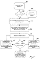
- FIG. 4 shows a programming process of the control device 21 or the switching device 12 using a flowchart.
- the key number 1 which is arranged on the guitar and is designed as a key switch and is connected to the control device 21 via the connecting element 11a, is pressed.
- a key with a stored switching state of the switches 4 is assigned to the button number 1 in the control device 21.
- the duration of the key press is monitored and, if the key is pressed for less than two seconds, the method is switched to method step 31.
- the state stored for key number 1 is applied to the individual switching signal lines 5a, 5b, 5c, 5d, 5e, 5f, 5g, 5h, 5i, 5j, 5k and the switches 4a, 4b, 4c, 4d, 4e, 4f, 4g , 4h, 4i, 4j, 4k switched accordingly, so that when the strings are actuated, an output signal S can be generated with a corresponding connection of the coils 14a, 14b, 15a, 15b, 16a.
- the respectively saved switching state can be set by actuating switches number 2, number 3 etc.
- the control device 21 changes to a programming mode and a speech signal Sp is generated in the following method step 33 with the content "swich number one is now in programming mode".
- a voice signal Sp is then output in method step 34 with the designation of the switching state currently in the memory, for example by the message “neck and bridge”, which means that the coil 14a is connected in parallel with the coil 14b, the coil 15a in parallel is connected to the coil 15b, and both parallel connections are connected in series.
- the switches 4 are also switched in accordance with this memory content, so that the tonality of this output signal S can be heard by operating the strings.
- a subsequent method step 35 the Push button with button number 1 pressed again, whereby the time period is monitored in method step 36.
- the key switch is pressed briefly once, it takes place a branch to process step 38, which causes from a fixed list of Switching states of the next state to switches 4 is applied and also with a speech signal Sp also is output acoustically, e.g. through the message "neck and brige outer coil parallel".
- a speech signal Sp also is output acoustically, e.g. through the message "neck and brige outer coil parallel”.
- By pressing the strings can turn the newly set combination be heard.
- pressing the Key number 1 takes place after method step 36 further branch to method step 38, so the next, in the fixed list of Switching states stored state at the switch 4 created and at the same time output acoustically.
- button number 1 is either for more than two seconds to press or it has no key input for more than thirty seconds more to be done, so that from step 36 to Method step 39 is branched, the The programming process ends with the message "Switch number one the setting has now been saved " Combination is thus saved and can be used at any time by pressing button number 1, as with Method step 31 shown can be called. Becomes briefly pressed the key twice in method step 36, branching to method step 37 and it is done in the list of fixed ones Switching states a return, that means in comparison to step 36, a jump to the opposite Direction. Thus, one or two times Pressing the key switch in step 36 in the fixed list of switching states to jump forward or backward.
- the flow chart shown is only an example from a variety of ways to look at how the control device 21 could be programmed.
- Tonality of the output signal S influencing Components such as capacitors, through which Control device 21 can be controlled programmably, to change the output signal S and one more greater variety of selectable sound variations enable.
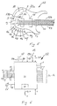
- FIG. 5 shows a guitar 22 with body 22a, neck 22b, Strings 23 and pickups 14.15.
- the bridge 25 are Pressure or tension sensors arranged which measure the tension allow to measure the individual strings 23 and the Voltage values through the signal line 28 of the Transmit switching device 12.
- the programmable switching device 12 Inside the body 22a is the programmable switching device 12 arranged, which via electrical signal lines 2, 13, 28 with the coils 14, 15, the sensors of the bridge 25 as well as the operating switches 11a, 11b, 11c, 11d, 11e, 11f, 11g.
- the output signal S and the speech signal Sp of the switching device 12 can on the electrical connector 3, which is a socket is designed for a plug of a cable, be tapped.
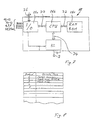
- Fig. 6 shows another embodiment of a programmable switching device 12, which a programmable control device 21 and a Voice signal generating device 20 includes.
- the switches 11a, 11b, 11c, 11d, 11e, 11f, 11g include which via signal lines 13 to the control device 21 are connected.
- These funds can continue, for example a controller 26, a measuring device for the to Lines 27a, 27b applied voltage of the battery 27, a signal line 28 for a pressure or tension sensor or the output signal S of individual coils or all Include coils.
- An electric guitar can do one Have a variety of states, which correspond with designed means detectable and the Control device 21 can be fed.
- the Programmable switching device 12 comprising the Control device 21 can, as in FIG. 7, for example shown consist of a microprocessor (CPU) 21b, which via data lines D2, D3, D4 with an input / output device (I / O) 21a, with a memory 12c (RAM, ROM) as well as with the Voice signal generating device 20 is connected.
- a microprocessor (CPU) 21b which via data lines D2, D3, D4 with an input / output device (I / O) 21a, with a memory 12c (RAM, ROM) as well as with the Voice signal generating device 20 is connected.
- the input / output device 21a becomes all states of the Lines 10,13,2a-2j, 6,7,8,28,29a recorded.
- the signal S the coils 17, 18, 19 are detected via the lines 2a-2j and individually or as a sum signal S of the interconnected Coils 17, 18, 19 from the input / output device 21a of the Speech signal generating device 20 supplied.
- the voice signal generating device 20 8 comprises a table according to FIG different states and corresponding texts, Voice or music signals are stored.
- the States can be saved as alphanumeric text be, the speech signal generating device 20 from this text a synthetic speech signal Sp allowed to generate.
- This initially electrical voice signal Sp is in via an internal or external speaker an acoustic signal is converted.
- the description of the States can also be considered in digitized form stored acoustic signals are stored, wherein these signals via a digital / analog converter as Speech signal Sp are output.
- An advantage of It stores the signals in digitized form to see that signals with any content can be stored are, including entire welcoming texts, identifications, Comments or advertising material, which in addition to language can also include music.
- the programmable switching device 12 can be external be programmable by connecting to the external digital line D1 for example a computer is connected, where also the table shown in Fig. 8 with assignment of States and corresponding voice signals programmable are.
- the programmable switching device 12 can also be designed without digital line D1, with Example, as shown in Fig. 6, an analog or digital input 29 can be provided, via which for example via a microphone, directly a speech signal can be stored in the table according to FIG. 8. So could one Guitar players in a very simple way too for example, a greeting directly via a microphone save as state in the table of FIG. 8, and by operating switches 11a, 11b, 11c, 11d, 11e, 11f, 11g call at a suitable time and as Speech signal Sp a downstream speaker respectively.
- the memory 21c arranged in the guitar can be used as Read only memory (ROM) as volatile memory (RAM) or as megnetic memory like a floppy disk, a hard disk or an optical memory like a megnet optical disk, a compact disk or a mini disk.
- ROM Read only memory
- RAM volatile memory
- megnetic memory like a floppy disk, a hard disk or an optical memory like a megnet optical disk, a compact disk or a mini disk.
Landscapes
- Physics & Mathematics (AREA)
- Engineering & Computer Science (AREA)
- Acoustics & Sound (AREA)
- Multimedia (AREA)
- Electrophonic Musical Instruments (AREA)
- Binders And Loading Units For Sheaves (AREA)
Claims (14)
- Dispositif de sélection de capteurs (1) pour un instrument à cordes comprenant plusieurs capteurs (14, 15, 16, 17, 18, 19), en particulier une guitare électrique,
comprenant un dispositif de sélection actionnable (12), qui est prévu pour connecter les bobines (14a, 14b, 15a, 15b, 16a, 17a, 18a, 19a) des capteurs (14, 15, 16, 17, 18, 19) suivant des combinaisons différentes pour générer un signal de sortie (S) de tonalité différente, caractérisé par un dispositif pour la production d'un signal vocal (20) qui génère un signal vocal (Sp) désignant l'état en fonction de l'état respectif du dispositif de sélection (12). - Dispositif de sélection de capteurs (1) selon la revendication 1, caractérisé en ce que le dispositif de sélection (12) est réalisé en tant que dispositif de commande électronique (21) avec des sélecteurs (4) commandables de manière sélective, en ce que chaque bobine (14a, 14b, 15a, 15b, 16a, 17a, 18a, 19a) peut être connectée à l'un des sélecteurs (4), et en ce que l'on utilise en particulier des sélecteurs (4) actionnables électromagnétiquement ou électroniquement, en particulier présentant un transistor FET.
- Dispositif de sélection de capteurs (1) selon la revendication 2, caractérisé en ce que le dispositif de commande électronique (21) est programmable et présente une mémoire.
- Dispositif de sélection de capteurs (1) selon l'une quelconque des revendications précédentes, caractérisé en ce que le dispositif pour la production d'un signal vocal (20) génère pendant la programmation un signal vocal (Sp) désignant l'état respectif.
- Dispositif de sélection de capteurs (1) selon l'une quelconque des revendications précédentes, caractérisé en ce que le dispositif de sélection (12) achemine, à une sortie électrique (3), soit le signal de sortie (S), soit le signal vocal (Sp), soit une superposition du signal de sortie (S) et du signal vocal (Sp).
- Dispositif de sélection de capteurs (1) selon l'une quelconque des revendications précédentes, caractérisé en ce que le dispositif pour la production d'un signal vocal (20) fait partie du dispositif de commande (21).
- Dispositif de sélection de capteurs (1) selon l'une quelconque des revendications 2 à 6, caractérisé en ce qu'un moyen d'entrée peut être connecté au dispositif de commande (21), et en ce que le moyen d'entrée est réalisé en particulier en tant que sélecteur ou en tant que dispositif de sélection électronique qui détecte un contact de la corde avec le capteur respectif (14, 15, 16, 17, 18, 19).
- Procédé pour régler un dispositif de sélection de capteurs (1) pour un instrument à cordes comprenant plusieurs capteurs (14, 15, 16, 17, 18, 19), en particulier une guitare électrique, dans lequel une pluralité d'états de connexion de bobines (14a, 14b, 15a, 15b, 16a, 17a, 18a, 19a) des capteurs (14, 15, 16, 17, 18, 19) est donnée, un état est sélectionné avec un dispositif de sélection actionnable (12), et les bobines (14a, 14b, 15a, 15b, 16a, 17a, 18a, 19a) sont connectées en conséquence, caractérisé en ce qu'un signal vocal (Sp) est généré, lequel décrit avec des mots l'état sélectionné.
- Procédé selon la revendication 8, caractérisé en ce que, pendant une programmation du dispositif de sélection (12), un signal vocal (Sp) est généré, lequel décrit avec des mots l'état respectif, et en ce qu'après avoir effectué un choix d'un état de connexion des bobines (14a, 14b, 15a, 15b, 16a, 17a, 18a, 19a), leur signal de sortie (S) est émis, afin que l'on puisse entendre la tonalité du signal de sortie (S) par l'actionnement des cordes.
- Instrument à cordes, en particulier une guitare, présentant un dispositif de sélection de capteurs selon l'une quelconque des revendications 1 à 7, ou actionné par un procédé selon l'une quelconque des revendications 8 à 9.
- Instrument à cordes à capteurs (14, 15, 16, 17, 18, 19), comprenant un dispositif de sélection de capteurs selon l'une quelconque des revendications 1 à 7, caractérisé par un dispositif pour la production d'un signal vocal (20) ainsi que par des moyens (11a, 11b, 11c, 11d, 11e, 11f, 11g) pour détecter un état de l'instrument à cordes et un moyen (21) pour acheminer l'état détecté au dispositif pour la production d'un signal vocal (20), le dispositif pour la production d'un signal vocal (20) présentant des moyens pour générer, en fonction de l'état détecté, un signal vocal correspondant (Sp), qui peut être acheminé à un convertisseur électroacoustique.
- Instrument à cordes selon la revendication 11, caractérisé en ce que les moyens pour détecter un état de l'instrument à cordes sont réalisés en tant que sélecteur (11a, 11b, 11c, 11d, 11e, 11f, 11g), en tant que régulateur (26), en tant qu'interface numérique (D1), ou en tant que détecteur tel qu'une bobine (17, 18, 19), un détecteur de traction (25), un détecteur de pression (24) ou un détecteur de tension.
- Instrument à cordes selon l'une quelconque des revendications 11 ou 12, caractérisé en ce que le moyen (21) pour acheminer l'état détecté au dispositif pour produire un signal vocal (20) est réalisé en tant que microprocesseur (21b) comprenant un dispositif d'entrée/sortie (21a) et une mémoire (21c).
- Instrument à cordes selon l'une quelconque des revendications 11 à 13, caractérisé en ce que le dispositif pour produire un signal vocal (20) comprend un tableau dans lequel différents états et les signaux vocaux correspondants (Sp) peuvent être mémorisés.
Applications Claiming Priority (4)
| Application Number | Priority Date | Filing Date | Title |
|---|---|---|---|
| CH63497 | 1997-03-17 | ||
| CH63497 | 1997-03-17 | ||
| PCT/CH1998/000102 WO1998041972A1 (fr) | 1997-03-17 | 1998-03-17 | Dispositif de selection de micros pour instrument a cordes, et instrument a cordes |
| US09/189,007 US6316713B1 (en) | 1997-03-17 | 1998-11-09 | Sound pickup switching apparatus for a string instrument having a plurality of sound pickups |
Publications (2)
| Publication Number | Publication Date |
|---|---|
| EP0968496A1 EP0968496A1 (fr) | 2000-01-05 |
| EP0968496B1 true EP0968496B1 (fr) | 2002-06-05 |
Family
ID=25685201
Family Applications (1)
| Application Number | Title | Priority Date | Filing Date |
|---|---|---|---|
| EP98906786A Expired - Lifetime EP0968496B1 (fr) | 1997-03-17 | 1998-03-17 | Dispositif de selection de micros pour instrument a cordes, et instrument a cordes |
Country Status (9)
| Country | Link |
|---|---|
| US (1) | US6316713B1 (fr) |
| EP (1) | EP0968496B1 (fr) |
| JP (1) | JP3220729B2 (fr) |
| AT (1) | ATE218738T1 (fr) |
| AU (1) | AU6287898A (fr) |
| CA (1) | CA2284021A1 (fr) |
| DE (1) | DE59804327D1 (fr) |
| ES (1) | ES2178168T3 (fr) |
| WO (1) | WO1998041972A1 (fr) |
Families Citing this family (25)
| Publication number | Priority date | Publication date | Assignee | Title |
|---|---|---|---|---|
| US6610917B2 (en) * | 1998-05-15 | 2003-08-26 | Lester F. Ludwig | Activity indication, external source, and processing loop provisions for driven vibrating-element environments |
| US7220912B2 (en) * | 1999-04-26 | 2007-05-22 | Gibson Guitar Corp. | Digital guitar system |
| US6998529B2 (en) * | 2001-07-20 | 2006-02-14 | Thomas Fredrick Wnorowski | Method for switching electric guitar pickups |
| US7457423B2 (en) * | 2001-08-06 | 2008-11-25 | Lazzeroni John J | Multi-accessory vehicle audio system, switch and method |
| US7220913B2 (en) * | 2003-01-09 | 2007-05-22 | Gibson Guitar Corp. | Breakout box for digital guitar |
| US7166794B2 (en) * | 2003-01-09 | 2007-01-23 | Gibson Guitar Corp. | Hexaphonic pickup for digital guitar system |
| EP1581925A4 (fr) * | 2003-01-09 | 2008-10-15 | Gibson Guitar Corp | Guitare numerique |
| US20050150364A1 (en) * | 2004-01-12 | 2005-07-14 | Paul Reed Smith Guitars, Limited Partnership | Multi-mode multi-coil pickup and pickup system for stringed musical instruments |
| US7288713B2 (en) * | 2004-01-14 | 2007-10-30 | Paul Reed Smith Guitars, Limited Partnership | Bobbin and pickup for stringed musical instruments |
| US7276657B2 (en) * | 2004-03-15 | 2007-10-02 | Bro William J | Maximized sound pickup switching apparatus for a string instrument having a plurality of sound pickups |
| US20060156912A1 (en) * | 2005-01-19 | 2006-07-20 | Annis Ross A | Electric guitar with cascaded voice and mode controls and laminated through body and method thereof |
| US7521628B2 (en) * | 2006-04-05 | 2009-04-21 | Joel Armstrong-Muntner | Electrical musical instrument with user interface and status display |
| US8445770B2 (en) * | 2008-06-14 | 2013-05-21 | Bruce Ledley Jacob | Programable switch for configuring circuit topologies |
| EP2200016A1 (fr) * | 2008-12-17 | 2010-06-23 | Goodbuy Corporation S.A. | Système de prise de son électroacoustique pour un instrument à cordes |
| US8324495B2 (en) * | 2009-02-13 | 2012-12-04 | Bruce Ledley Jacob | Volume-adjustment circuit for equilibrating pickup settings |
| US8796531B2 (en) | 2010-07-15 | 2014-08-05 | Ambrosonics, Llc | Programmable pickup director switching system and method of use |
| US20120240751A1 (en) * | 2011-03-23 | 2012-09-27 | Ayako Yonetani | Hybrid stringed instrument |
| JP5739298B2 (ja) * | 2011-10-03 | 2015-06-24 | 有限会社ヴィンテージ・ギターズ | 弦楽器用ピックアップ |
| JP2013178509A (ja) * | 2012-02-07 | 2013-09-09 | Yamaha Corp | 電子装置、及び音声ガイド用プログラム |
| US11087731B2 (en) * | 2014-07-23 | 2021-08-10 | Donald L Baker | Humbucking pair building block circuit for vibrational sensors |
| US10217450B2 (en) * | 2017-06-07 | 2019-02-26 | Donald L Baker | Humbucking switching arrangements and methods for stringed instrument pickups |
| US11011146B2 (en) * | 2014-07-23 | 2021-05-18 | Donald L Baker | More embodiments for common-point pickup circuits in musical instruments part C |
| JP6497773B2 (ja) * | 2015-03-02 | 2019-04-10 | 株式会社コルグ | 電子ギターの操作子設定装置およびプログラム |
| FR3079655B1 (fr) | 2018-04-03 | 2020-03-27 | Wild Customs | Dispositif pour interchanger des systemes electriques ou electroniques de captation des vibrations des cordes d'un instrument de musique |
| US20220051648A1 (en) * | 2020-08-12 | 2022-02-17 | Chad Gerber | Midi controller and system for distributing media therewith |
Family Cites Families (14)
| Publication number | Priority date | Publication date | Assignee | Title |
|---|---|---|---|---|
| US3915048A (en) * | 1974-08-05 | 1975-10-28 | Norlin Music Inc | Electric guitar circuit |
| US4151776A (en) * | 1975-06-20 | 1979-05-01 | Norlin Industries, Inc. | Electronic pickup system for stringed musical instrument |
| US4175462A (en) * | 1977-06-17 | 1979-11-27 | Simon Jonathan C | System for selection and phase control of humbucking coils in guitar pickups |
| JPS5695295A (en) * | 1979-12-28 | 1981-08-01 | Sharp Kk | Voice sysnthesis and control circuit |
| US4733591A (en) * | 1984-05-30 | 1988-03-29 | Nippon Gakki Seizo Kabushiki Kaisha | Electronic musical instrument |
| JPH0713797B2 (ja) * | 1985-01-31 | 1995-02-15 | ヤマハ株式会社 | 電子楽器 |
| US4711149A (en) | 1985-07-12 | 1987-12-08 | Starr Harvey W | Electric guitar pickup switching system |
| US5136919A (en) * | 1990-01-18 | 1992-08-11 | Gibson Guitar Corp. | Guitar pickup and switching apparatus |
| JPH04255899A (ja) * | 1991-02-08 | 1992-09-10 | Nec Corp | 音声合成lsi |
| JP3006923B2 (ja) * | 1991-08-07 | 2000-02-07 | ヤマハ株式会社 | 電子楽器 |
| US5399800A (en) * | 1992-01-28 | 1995-03-21 | Kabushiki Kaisha Kawai Gakki Seisakusho | Electronic musical instrument including an apparatus for aurally and visually displaying specification explanations and states of the electronic musical instrument |
| US5311806A (en) * | 1993-01-15 | 1994-05-17 | Gibson Guitar Corp. | Guitar pickup system for selecting from multiple tonalities |
| GB2309815B (en) * | 1996-01-31 | 1999-11-10 | Patrick Geoffrey Thomson | Switching apparatus for electric guitar pickups |
| US5780760A (en) * | 1997-01-13 | 1998-07-14 | Gibson Guitar Corp. | Guitar pickup switching system for three-pickup guitar |
-
1998
- 1998-03-17 AT AT98906786T patent/ATE218738T1/de not_active IP Right Cessation
- 1998-03-17 CA CA002284021A patent/CA2284021A1/fr not_active Abandoned
- 1998-03-17 DE DE59804327T patent/DE59804327D1/de not_active Expired - Fee Related
- 1998-03-17 ES ES98906786T patent/ES2178168T3/es not_active Expired - Lifetime
- 1998-03-17 JP JP53999198A patent/JP3220729B2/ja not_active Expired - Fee Related
- 1998-03-17 WO PCT/CH1998/000102 patent/WO1998041972A1/fr not_active Ceased
- 1998-03-17 AU AU62878/98A patent/AU6287898A/en not_active Abandoned
- 1998-03-17 EP EP98906786A patent/EP0968496B1/fr not_active Expired - Lifetime
- 1998-11-09 US US09/189,007 patent/US6316713B1/en not_active Expired - Fee Related
Also Published As
| Publication number | Publication date |
|---|---|
| ATE218738T1 (de) | 2002-06-15 |
| JP3220729B2 (ja) | 2001-10-22 |
| ES2178168T3 (es) | 2002-12-16 |
| JP2000512400A (ja) | 2000-09-19 |
| WO1998041972A1 (fr) | 1998-09-24 |
| AU6287898A (en) | 1998-10-12 |
| US6316713B1 (en) | 2001-11-13 |
| EP0968496A1 (fr) | 2000-01-05 |
| CA2284021A1 (fr) | 1998-09-24 |
| DE59804327D1 (de) | 2002-07-11 |
Similar Documents
| Publication | Publication Date | Title |
|---|---|---|
| EP0968496B1 (fr) | Dispositif de selection de micros pour instrument a cordes, et instrument a cordes | |
| DE60307576T2 (de) | Verfahren zum Einstellen eines Hörgerätes an eine momentane akustische Umgebungssituation und ein Hörgerätsystem | |
| DE2526457C3 (de) | Elektronisches Musikinstrument | |
| DE19735039A1 (de) | Tonsignalmischer und -verfahren mit Schaltpult | |
| EP2207646A1 (fr) | Commande d'appareil à effet | |
| DE19730251B4 (de) | Resonator-Saiteninstrument | |
| DE112020006211T5 (de) | Steuervorrichtung, Signalverarbeitungsverfahren und Lautsprechervorrichtung | |
| DE4141843B4 (de) | Verfahren zur Steuerung der Signalwiedergabe von gemischten Musik- und Sprachsignalen, Schaltungsanordnungen zum Durchführen des Verfahrens sowie Anwendungen des Verfahrens bzw. der Schaltungsanordnung | |
| DE2625922C3 (de) | Wiedergabeverstärker für Instrumentalisten, Sänger und Orchester | |
| CH700498B1 (de) | Gitarre mit eingebauten Tonverstärker, Lautsprecher und Effektengerät. | |
| DE2336425A1 (de) | Einrichtung zum vorzugsweisen waehlen von hohen oder niedrigen toenen fuer elektrische musikinstrumente mit tastatur | |
| DE19882351C2 (de) | Vorrichtung zur Tonsimulation von Orchestermusik | |
| DE4406942A1 (de) | Tonabnehmersystem für Gitarren oder andere Saiteninstrumente | |
| EP2200016A1 (fr) | Système de prise de son électroacoustique pour un instrument à cordes | |
| DE19511564C2 (de) | Tonverstärker und Stimmgerät | |
| DE10030899B4 (de) | Musikinstrument | |
| DE2002334A1 (de) | Musikverstaerker mit Einrichtung fuer das Stimmen von Musikinstrumenten | |
| DE202005000536U1 (de) | 10 Kanal Stereo "In-Ear-Monitoring" Mischpult | |
| DE10049279B4 (de) | Zither | |
| EP1766607A1 (fr) | Amplificateur pour instruments de musique, notamment amplificateur pour guitare | |
| DE2338513A1 (de) | Elektronisches musikinstrument | |
| DE4340686C2 (de) | Vorrichtung zum Erzeugen von räumlichen Klangeffekten bei elektronischen Musikinstrumenten | |
| DE9109889U1 (de) | Leistungsverstärker mit zwei Betriebsarten | |
| DE2604954A1 (de) | Lautsprecher-anordnung, insbesondere schaltung aus mehreren lautsprechern | |
| DE102016013308A1 (de) | Verbessertes musikgerät mit rechner |
Legal Events
| Date | Code | Title | Description |
|---|---|---|---|
| PUAI | Public reference made under article 153(3) epc to a published international application that has entered the european phase |
Free format text: ORIGINAL CODE: 0009012 |
|
| 17P | Request for examination filed |
Effective date: 19990913 |
|
| AK | Designated contracting states |
Kind code of ref document: A1 Designated state(s): AT BE CH DE DK ES FI FR GB GR IE IT LI LU MC NL PT SE |
|
| GRAG | Despatch of communication of intention to grant |
Free format text: ORIGINAL CODE: EPIDOS AGRA |
|
| 17Q | First examination report despatched |
Effective date: 20010710 |
|
| GRAG | Despatch of communication of intention to grant |
Free format text: ORIGINAL CODE: EPIDOS AGRA |
|
| GRAH | Despatch of communication of intention to grant a patent |
Free format text: ORIGINAL CODE: EPIDOS IGRA |
|
| GRAH | Despatch of communication of intention to grant a patent |
Free format text: ORIGINAL CODE: EPIDOS IGRA |
|
| GRAA | (expected) grant |
Free format text: ORIGINAL CODE: 0009210 |
|
| AK | Designated contracting states |
Kind code of ref document: B1 Designated state(s): AT BE CH DE DK ES FI FR GB GR IE IT LI LU MC NL PT SE |
|
| PG25 | Lapsed in a contracting state [announced via postgrant information from national office to epo] |
Ref country code: GR Free format text: LAPSE BECAUSE OF FAILURE TO SUBMIT A TRANSLATION OF THE DESCRIPTION OR TO PAY THE FEE WITHIN THE PRESCRIBED TIME-LIMIT Effective date: 20020605 Ref country code: FI Free format text: LAPSE BECAUSE OF FAILURE TO SUBMIT A TRANSLATION OF THE DESCRIPTION OR TO PAY THE FEE WITHIN THE PRESCRIBED TIME-LIMIT Effective date: 20020605 |
|
| REF | Corresponds to: |
Ref document number: 218738 Country of ref document: AT Date of ref document: 20020615 Kind code of ref document: T |
|
| REG | Reference to a national code |
Ref country code: GB Ref legal event code: FG4D Free format text: NOT ENGLISH |
|
| REG | Reference to a national code |
Ref country code: CH Ref legal event code: EP |
|
| REG | Reference to a national code |
Ref country code: IE Ref legal event code: FG4D Free format text: GERMAN |
|
| REF | Corresponds to: |
Ref document number: 59804327 Country of ref document: DE Date of ref document: 20020711 |
|
| PG25 | Lapsed in a contracting state [announced via postgrant information from national office to epo] |
Ref country code: SE Free format text: LAPSE BECAUSE OF FAILURE TO SUBMIT A TRANSLATION OF THE DESCRIPTION OR TO PAY THE FEE WITHIN THE PRESCRIBED TIME-LIMIT Effective date: 20020905 Ref country code: PT Free format text: LAPSE BECAUSE OF FAILURE TO SUBMIT A TRANSLATION OF THE DESCRIPTION OR TO PAY THE FEE WITHIN THE PRESCRIBED TIME-LIMIT Effective date: 20020905 Ref country code: DK Free format text: LAPSE BECAUSE OF FAILURE TO SUBMIT A TRANSLATION OF THE DESCRIPTION OR TO PAY THE FEE WITHIN THE PRESCRIBED TIME-LIMIT Effective date: 20020905 |
|
| REG | Reference to a national code |
Ref country code: CH Ref legal event code: NV Representative=s name: PATENTANWAELTE SCHAAD, BALASS, MENZL & PARTNER AG |
|
| GBT | Gb: translation of ep patent filed (gb section 77(6)(a)/1977) |
Effective date: 20020906 |
|
| ET | Fr: translation filed | ||
| REG | Reference to a national code |
Ref country code: ES Ref legal event code: FG2A Ref document number: 2178168 Country of ref document: ES Kind code of ref document: T3 |
|
| PG25 | Lapsed in a contracting state [announced via postgrant information from national office to epo] |
Ref country code: LU Free format text: LAPSE BECAUSE OF NON-PAYMENT OF DUE FEES Effective date: 20030317 |
|
| PG25 | Lapsed in a contracting state [announced via postgrant information from national office to epo] |
Ref country code: MC Free format text: LAPSE BECAUSE OF NON-PAYMENT OF DUE FEES Effective date: 20030331 |
|
| PLBE | No opposition filed within time limit |
Free format text: ORIGINAL CODE: 0009261 |
|
| STAA | Information on the status of an ep patent application or granted ep patent |
Free format text: STATUS: NO OPPOSITION FILED WITHIN TIME LIMIT |
|
| 26N | No opposition filed |
Effective date: 20030306 |
|
| PGFP | Annual fee paid to national office [announced via postgrant information from national office to epo] |
Ref country code: IE Payment date: 20040218 Year of fee payment: 7 |
|
| PGFP | Annual fee paid to national office [announced via postgrant information from national office to epo] |
Ref country code: NL Payment date: 20040227 Year of fee payment: 7 |
|
| PGFP | Annual fee paid to national office [announced via postgrant information from national office to epo] |
Ref country code: AT Payment date: 20040303 Year of fee payment: 7 |
|
| PGFP | Annual fee paid to national office [announced via postgrant information from national office to epo] |
Ref country code: BE Payment date: 20040512 Year of fee payment: 7 |
|
| REG | Reference to a national code |
Ref country code: CH Ref legal event code: NV Representative=s name: FELBER & PARTNER AG PATENTANWAELTE |
|
| PGFP | Annual fee paid to national office [announced via postgrant information from national office to epo] |
Ref country code: CH Payment date: 20050314 Year of fee payment: 8 |
|
| PGFP | Annual fee paid to national office [announced via postgrant information from national office to epo] |
Ref country code: GB Payment date: 20050316 Year of fee payment: 8 |
|
| PG25 | Lapsed in a contracting state [announced via postgrant information from national office to epo] |
Ref country code: IE Free format text: LAPSE BECAUSE OF NON-PAYMENT OF DUE FEES Effective date: 20050317 Ref country code: AT Free format text: LAPSE BECAUSE OF NON-PAYMENT OF DUE FEES Effective date: 20050317 |
|
| PGFP | Annual fee paid to national office [announced via postgrant information from national office to epo] |
Ref country code: FR Payment date: 20050324 Year of fee payment: 8 Ref country code: DE Payment date: 20050324 Year of fee payment: 8 |
|
| PG25 | Lapsed in a contracting state [announced via postgrant information from national office to epo] |
Ref country code: BE Free format text: LAPSE BECAUSE OF NON-PAYMENT OF DUE FEES Effective date: 20050331 |
|
| PGFP | Annual fee paid to national office [announced via postgrant information from national office to epo] |
Ref country code: ES Payment date: 20050429 Year of fee payment: 8 |
|
| BERE | Be: lapsed |
Owner name: *BOXER & FURST A.G. Effective date: 20050331 |
|
| PG25 | Lapsed in a contracting state [announced via postgrant information from national office to epo] |
Ref country code: NL Free format text: LAPSE BECAUSE OF NON-PAYMENT OF DUE FEES Effective date: 20051001 |
|
| NLV4 | Nl: lapsed or anulled due to non-payment of the annual fee |
Effective date: 20051001 |
|
| REG | Reference to a national code |
Ref country code: IE Ref legal event code: MM4A |
|
| PG25 | Lapsed in a contracting state [announced via postgrant information from national office to epo] |
Ref country code: GB Free format text: LAPSE BECAUSE OF NON-PAYMENT OF DUE FEES Effective date: 20060317 |
|
| PG25 | Lapsed in a contracting state [announced via postgrant information from national office to epo] |
Ref country code: ES Free format text: LAPSE BECAUSE OF NON-PAYMENT OF DUE FEES Effective date: 20060318 |
|
| PG25 | Lapsed in a contracting state [announced via postgrant information from national office to epo] |
Ref country code: LI Free format text: LAPSE BECAUSE OF NON-PAYMENT OF DUE FEES Effective date: 20060331 Ref country code: CH Free format text: LAPSE BECAUSE OF NON-PAYMENT OF DUE FEES Effective date: 20060331 |
|
| PGFP | Annual fee paid to national office [announced via postgrant information from national office to epo] |
Ref country code: IT Payment date: 20060331 Year of fee payment: 9 |
|
| PG25 | Lapsed in a contracting state [announced via postgrant information from national office to epo] |
Ref country code: DE Free format text: LAPSE BECAUSE OF NON-PAYMENT OF DUE FEES Effective date: 20061003 |
|
| REG | Reference to a national code |
Ref country code: CH Ref legal event code: PL |
|
| GBPC | Gb: european patent ceased through non-payment of renewal fee |
Effective date: 20060317 |
|
| REG | Reference to a national code |
Ref country code: FR Ref legal event code: ST Effective date: 20061130 |
|
| REG | Reference to a national code |
Ref country code: ES Ref legal event code: FD2A Effective date: 20060318 |
|
| BERE | Be: lapsed |
Owner name: *BOXER & FURST A.G. Effective date: 20050331 |
|
| PG25 | Lapsed in a contracting state [announced via postgrant information from national office to epo] |
Ref country code: FR Free format text: LAPSE BECAUSE OF NON-PAYMENT OF DUE FEES Effective date: 20060331 |
|
| PG25 | Lapsed in a contracting state [announced via postgrant information from national office to epo] |
Ref country code: IT Free format text: LAPSE BECAUSE OF NON-PAYMENT OF DUE FEES Effective date: 20070317 |