EP0968685A2 - Dispositif pour le traitement des fractures des os - Google Patents
Dispositif pour le traitement des fractures des os Download PDFInfo
- Publication number
- EP0968685A2 EP0968685A2 EP99112136A EP99112136A EP0968685A2 EP 0968685 A2 EP0968685 A2 EP 0968685A2 EP 99112136 A EP99112136 A EP 99112136A EP 99112136 A EP99112136 A EP 99112136A EP 0968685 A2 EP0968685 A2 EP 0968685A2
- Authority
- EP
- European Patent Office
- Prior art keywords
- hole
- sleeve
- locking nail
- extension
- rotation pin
- Prior art date
- Legal status (The legal status is an assumption and is not a legal conclusion. Google has not performed a legal analysis and makes no representation as to the accuracy of the status listed.)
- Granted
Links
- 208000010392 Bone Fractures Diseases 0.000 title claims abstract description 4
- 210000000689 upper leg Anatomy 0.000 claims abstract description 9
- 210000002436 femur neck Anatomy 0.000 claims abstract description 7
- 210000000988 bone and bone Anatomy 0.000 claims description 18
- 208000006670 Multiple fractures Diseases 0.000 claims description 2
- 238000011144 upstream manufacturing Methods 0.000 claims description 2
- 239000012634 fragment Substances 0.000 description 11
- 238000010276 construction Methods 0.000 description 4
- 230000009286 beneficial effect Effects 0.000 description 2
- 238000006073 displacement reaction Methods 0.000 description 2
- 230000035876 healing Effects 0.000 description 2
- 238000003780 insertion Methods 0.000 description 2
- 230000037431 insertion Effects 0.000 description 2
- 230000002093 peripheral effect Effects 0.000 description 2
- 230000003313 weakening effect Effects 0.000 description 2
- 208000020089 femoral neck fracture Diseases 0.000 description 1
- 238000004519 manufacturing process Methods 0.000 description 1
- 238000000034 method Methods 0.000 description 1
- 238000010079 rubber tapping Methods 0.000 description 1
- 230000007704 transition Effects 0.000 description 1
Images

Classifications
-
- A—HUMAN NECESSITIES
- A61—MEDICAL OR VETERINARY SCIENCE; HYGIENE
- A61B—DIAGNOSIS; SURGERY; IDENTIFICATION
- A61B17/00—Surgical instruments, devices or methods
- A61B17/56—Surgical instruments or methods for treatment of bones or joints; Devices specially adapted therefor
- A61B17/58—Surgical instruments or methods for treatment of bones or joints; Devices specially adapted therefor for osteosynthesis, e.g. bone plates, screws or setting implements
- A61B17/68—Internal fixation devices, including fasteners and spinal fixators, even if a part thereof projects from the skin
- A61B17/74—Devices for the head or neck or trochanter of the femur
- A61B17/742—Devices for the head or neck or trochanter of the femur having one or more longitudinal elements oriented along or parallel to the axis of the neck
- A61B17/744—Devices for the head or neck or trochanter of the femur having one or more longitudinal elements oriented along or parallel to the axis of the neck the longitudinal elements coupled to an intramedullary nail
Definitions
- the invention relates to a device for supply of broken bones in the proximal part of the joint Femoral bone with one in the medullary bone of the femur insertable locking nail that in his upper area a transverse to its longitudinal axis Has through hole, with one in this Through hole in the axial direction fixed sleeve, which at one end protrudes beyond its outer jacket Carries external thread, and with one with one Shank immersed in the sleeve and in the sleeve axially displaceable femoral neck screw.
- Such devices are known for example from EP 0 727 189 B1 or EP 0 599 752 B1.
- This task is the beginning of a device described type according to the invention solved in that the through hole has a smooth cylindrical inner wall has on which the sleeve with her also smooth outer jacket fits tightly, and that the through hole a step-shaped in the locking nail Extension is upstream on its side wall at least one essentially in the circumferential direction has running rib, which when screwing the Sleeve into the through hole between the threads of the external thread of the sleeve engages.
- the through hole remains with this construction smooth over their entire length, and remains the same the outer circumference of the sleeve in the insertion area in the Through hole smooth, so that both parts with little Game can be performed exactly relative to each other.
- the locking nail does not experience any of this Weakening, a smooth continuous cylindrical bore is easy to manufacture.
- Laying down the sleeve takes place in that the external thread of the sleeve and the Rib or the ribs on the side wall of the extension interlock.
- This allows the sleeve to go into the through hole for as long be screwed in until the external thread on the Sleeve against the step of the step-like expansion strikes. This gives you a defined location of the Sleeve in the locking nail, in which the sleeve in the locking nail by engaging the rib or the Ribs in the external thread is securely fixed.
- the rib can be threaded through an internal thread the side wall be formed so that this two threads on the side wall on the one hand and on the Outside of the sleeve on the other hand when screwing in Interlock sleeve.
- the rib exactly in one plane runs perpendicular to the longitudinal axis of the through hole stands.
- the rib is not Part of a thread, so has no pitch on, nevertheless, such a rib can with appropriate Dimensioning between the threads of the external thread engage the sleeve and thereby the sleeve in axial Set direction.
- the enlargement extends over the entire circumference of the through hole, however, in a preferred embodiment provided that the extension was only one Part of the circumference of the through hole extends.
- the extension with a diagonally leading through the locking nail Through hole on the side of the through hole connects the farthest over a vertical one the plane of the longitudinal axis of the through hole protrudes.
- the through hole arranged at an angle a plane perpendicular to the longitudinal axis of the Through hole is located. This will make the through hole longer on one side than on the opposite Side, and on this longer side closes the step-like expansion in this configuration which therefore continues to be within the outer circumference of the locking nail remains.
- a second through hole in the locking nail is arranged, which has an anti-rotation pin records.
- This parallel to the locking screw running anti-rotation pen also penetrates into the bone fragment to be fixed and secure this therefore prevents rotation about the longitudinal axis the femoral neck screw.
- the thread can be designed so that there is only one Part of the second through opening extends so that the screw depth is limited by the fact that the end of the external thread of the anti-rotation pin against the End of the internal thread in the second through hole strikes.
- the anti-rotation pin has its length protruding from the locking nail smooth cylindrical outer wall on, so that an axial displacement between bone fragment on the one hand and Anti-rotation pin on the other hand is not hindered.
- the anti-rotation pin has a pointed end, that is if necessary, when the bone fragments approach in the course of the healing process also deeper into that Can dig in the bone fragment.
- the anti-rotation pin has an outer diameter which is significantly smaller than that of the sleeve, for example, this can be less than half Diameter of the sleeve.
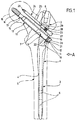
- the supply device shown in the drawing a femoral neck fracture includes a locking nail 1 with a cylindrical upper part 2 and an adjoining, tapered shaft 3.
- This locking nail 1 is in the medullary canal 4 of a femur bone 5 and inserted there through across the femur 5 screwed, not in the drawing shown screws set through cross holes 6 pass through in the area of the shaft 3. in the inserted state, the locking nail 1 is thereby recorded almost completely in the medullary canal 4.
- the Push shaft 3 across and opposite the longitudinal axis of the shaft 3 are inclined, for example around an angle of 50 °.
- the first through hole 7, which is closer to the shaft 3 lies, has a smooth, circular cylindrical inner wall 9 on, whose diameter over the entire length of the Through hole 7 is the same. Only at one end the through hole 7 increases the inner diameter the through hole 7 is stepped and forms thus an extension 10, the cylindrical inner wall 11 a plurality of ribs running parallel to one another 12 carries. This can be done by screwing one Be formed on the inner wall 11, the ribs can also be exactly in the circumferential direction run, i.e. without a slope in the longitudinal direction.
- the depth of the extension 10 is so small that the extension 10 due to the oblique course of the through hole 7 in the shaft 3 does not cover the entire Extends the peripheral region of the through hole 7, but only over the lower part, i.e. the part that is in immerses the outline of the shaft 3 on the opposite
- the through hole 7 ends with the smooth, cylindrical inner wall 9.
- the extension 10 thus forms in the illustrated Embodiment a trough-shaped depression on lower end of the otherwise completely cylindrical Through hole 7, and in this trough-shaped
- the ribs 12 are arranged in a recess.
- a possibly self-tapping bone thread 14 carries, which is a cylindrical Shaft 15 connects, the outer diameter clearly is smaller than the inner diameter of the inner wall 9 the through hole 7.
- the outside diameter of the bone thread 14 is chosen so that the locking screw 13 pushed through the through hole 7 and by means of a not shown in the drawing suitable tool in the to be fixed Bone fragment 16 can be screwed in.
- This sleeve 17 carries on the bone thread 14 facing away End of an external thread 18, the screw threads outwards via the cylindrical outer jacket 19 of the Project sleeve 17.
- depressions 21 are arranged, which is a turning tool, not shown in the drawing can record, with the help of the sleeve 17 can be rotated in the through hole 7.
- the screw-in depth of the sleeve 17 is limited.
- the sleeve 17 is practical in this construction along its entire length with the cylindrical Outer jacket 19 on the likewise cylindrical inner wall 9 of the through hole 7 and learns about it there optimal length, only in the area very in the longitudinal direction of the through hole short extension 10 there is an interference with the External thread 18, and thus the shaft 3 of the locking nail 1 in the exit area of the through hole 7 only slightly compared to a construction modified that no such extension with corresponding Ribs.
- the sleeve 17 is also very simply trained, its outer jacket is over the the entire length is of a cylindrical design, only in a short area is on this outer jacket the external thread 18 is attached.
- the second through hole 8 has one smaller diameter than the first through hole 7, for example, the inside diameter of the Through hole 8 smaller than 50% of the inner diameter the first through hole 7.
- the through hole 8 is from the insertion side developed gradually narrowing, expanded Part of it carries an internal thread 23, otherwise the inner walls executed smoothly.
- this second through hole 8 is an anti-rotation pin 24 screwed in, which is a smooth, cylindrical Has shaft 25 with a tip 26 and a adjoining, thickened cylindrical section 27, which in the transition area to the shaft 25 carries an external thread 28.
- the outside diameter of the Shank 25 corresponds to the inside diameter of the through hole 8 in the section with a smaller inner diameter, the outside diameter of the thickened section 27 of the anti-rotation pin 24, however, the outer diameter the second through hole 8 in the area with larger inner diameter.
- the anti-rotation pin 24 projects with its shaft 25 and its tip 26 into the bone fragment to be fixed 16 and prevents twisting of the bone fragment 16 around the longitudinal axis of the locking screw 13.
- the shaft 25 of the anti-rotation pin 24 is relatively thin and that the anti-rotation pin 24 with the tip 26 if necessary also deeper into the bone fragment 16 can dig in, is a relative displacement of the Bone fragment 16 to the anti-rotation pin 24 in the axial Direction possible, so that a possibly at Healing process approaching without further ado is possible.
Landscapes
- Health & Medical Sciences (AREA)
- Orthopedic Medicine & Surgery (AREA)
- Surgery (AREA)
- Life Sciences & Earth Sciences (AREA)
- Heart & Thoracic Surgery (AREA)
- Nuclear Medicine, Radiotherapy & Molecular Imaging (AREA)
- Engineering & Computer Science (AREA)
- Biomedical Technology (AREA)
- Neurology (AREA)
- Medical Informatics (AREA)
- Molecular Biology (AREA)
- Animal Behavior & Ethology (AREA)
- General Health & Medical Sciences (AREA)
- Public Health (AREA)
- Veterinary Medicine (AREA)
- Surgical Instruments (AREA)
Applications Claiming Priority (2)
| Application Number | Priority Date | Filing Date | Title |
|---|---|---|---|
| DE1998129228 DE19829228C1 (de) | 1998-06-30 | 1998-06-30 | Vorrichtung zur Versorgung von Knochenbrüchen |
| DE19829228 | 1998-06-30 |
Publications (3)
| Publication Number | Publication Date |
|---|---|
| EP0968685A2 true EP0968685A2 (fr) | 2000-01-05 |
| EP0968685A3 EP0968685A3 (fr) | 2002-03-27 |
| EP0968685B1 EP0968685B1 (fr) | 2004-09-01 |
Family
ID=7872536
Family Applications (1)
| Application Number | Title | Priority Date | Filing Date |
|---|---|---|---|
| EP19990112136 Expired - Lifetime EP0968685B1 (fr) | 1998-06-30 | 1999-06-24 | Dispositif pour le traitement des fractures des os |
Country Status (3)
| Country | Link |
|---|---|
| EP (1) | EP0968685B1 (fr) |
| DE (1) | DE19829228C1 (fr) |
| ES (1) | ES2226239T3 (fr) |
Cited By (13)
| Publication number | Priority date | Publication date | Assignee | Title |
|---|---|---|---|---|
| DE20219683U1 (de) * | 2002-12-19 | 2004-04-29 | Stryker Trauma Gmbh | Osteosynthesehilfsmittel |
| US6835197B2 (en) | 2001-10-17 | 2004-12-28 | Christoph Andreas Roth | Bone fixation system |
| JP2008068011A (ja) * | 2006-09-15 | 2008-03-27 | Japan Medical Materials Corp | 大腿骨近位部骨折用固定器具 |
| US7892234B2 (en) | 2004-06-22 | 2011-02-22 | Synthes Usa, Llc | Intramedullary nail |
| US8066706B2 (en) | 2004-06-30 | 2011-11-29 | Synthes Usa, Llc | Surgical nail |
| US8114079B2 (en) | 2008-03-31 | 2012-02-14 | Depuy Products, Inc. | Intramedullary nail with coupled shafts |
| US8221419B2 (en) | 2003-08-29 | 2012-07-17 | Synthes Usa, Llc | Intramedullary nail |
| US8465489B2 (en) | 2003-06-12 | 2013-06-18 | Synthes Usa, Llc | Surgical nail |
| US8641740B2 (en) | 2007-09-26 | 2014-02-04 | Zimmer, Gmbh | Bone anchoring device for the operative repair of fractures |
| US8888779B2 (en) | 2003-03-07 | 2014-11-18 | DePuy Synthes Products, LLC | Locking screw for an intramedullary nail |
| US8939978B2 (en) | 2007-03-20 | 2015-01-27 | Smith & Nephew, Inc. | Orthopaedic plate and screw assembly |
| US9237909B2 (en) | 2003-07-30 | 2016-01-19 | DePuy Synthes Products, Inc. | Surgical nail |
| US9737347B2 (en) | 2003-06-12 | 2017-08-22 | DePuy Synthes Products, Inc. | Surgical nail |
Families Citing this family (14)
| Publication number | Priority date | Publication date | Assignee | Title |
|---|---|---|---|---|
| DE20113345U1 (de) | 2001-08-17 | 2003-01-02 | Tantum AG, 24534 Neumünster | Femurfrakturnagel |
| US7632272B2 (en) | 2002-10-03 | 2009-12-15 | Synthes Usa, Llc | Device for bone fixation |
| DE10305348A1 (de) * | 2003-02-10 | 2004-08-26 | Cell Center Cologne Gmbh | Dynamische epiphysäre Teleskopschraube |
| US7455673B2 (en) * | 2003-07-08 | 2008-11-25 | Yechiel Gotfried | Intramedullary nail system and method for fixation of a fractured bone |
| US20050055024A1 (en) | 2003-09-08 | 2005-03-10 | James Anthony H. | Orthopaedic implant and screw assembly |
| US7780667B2 (en) | 2003-09-08 | 2010-08-24 | Smith & Nephew, Inc. | Orthopaedic plate and screw assembly |
| US7799030B2 (en) | 2003-09-08 | 2010-09-21 | Smith & Nephew, Inc. | Orthopaedic plate and screw assembly |
| JP4657104B2 (ja) * | 2003-09-18 | 2011-03-23 | ジンテーズ ゲゼルシャフト ミト ベシュレンクテル ハフツング | 大腿骨の骨折を治療するための装置 |
| DE102005039854B4 (de) * | 2005-08-23 | 2007-07-12 | Königsee Implantate und Instrumente zur Osteosynthese GmbH | Proximaler Femurnagel |
| US8100911B2 (en) | 2008-06-30 | 2012-01-24 | Depuy Products, Inc. | Fracture fixation apparatus |
| CN105726112B (zh) | 2009-06-30 | 2021-04-27 | 史密夫和内修有限公司 | 整形外科的植入物和紧固组件 |
| US8449544B2 (en) | 2009-06-30 | 2013-05-28 | Smith & Nephew, Inc. | Orthopaedic implant and fastener assembly |
| US9895177B2 (en) | 2016-01-15 | 2018-02-20 | ARTHREX, GmbH | Bone fixation device for treatment of femoral fractures |
| BR112019007255B1 (pt) * | 2016-10-10 | 2022-10-04 | Francisco Ferrero Manzanal | Sistema de fixação intramedular de ângulo variável para tratar fraturas femuras |
Citations (2)
| Publication number | Priority date | Publication date | Assignee | Title |
|---|---|---|---|---|
| EP0599752B1 (fr) | 1992-11-24 | 1997-04-23 | Fixano Sa | Dispositif d'ostéosynthèse pour fractures trochantérienne ou trochantéro-diaphysaire |
| EP0727189B1 (fr) | 1995-02-18 | 1998-04-01 | Aesculap Ag | Dispositif pour traiter des fractures d'os |
Family Cites Families (2)
| Publication number | Priority date | Publication date | Assignee | Title |
|---|---|---|---|---|
| IT1272537B (it) * | 1993-08-30 | 1997-06-23 | Synos Medical Spa | Chiodo endomidollare per la sintesi delle fratture del femore prossimale ed apparecchiatura per il suo posizionamento |
| DE29709725U1 (de) * | 1997-06-04 | 1997-08-21 | Aesculap AG & Co. KG, 78532 Tuttlingen | Implantat |
-
1998
- 1998-06-30 DE DE1998129228 patent/DE19829228C1/de not_active Expired - Lifetime
-
1999
- 1999-06-24 ES ES99112136T patent/ES2226239T3/es not_active Expired - Lifetime
- 1999-06-24 EP EP19990112136 patent/EP0968685B1/fr not_active Expired - Lifetime
Patent Citations (2)
| Publication number | Priority date | Publication date | Assignee | Title |
|---|---|---|---|---|
| EP0599752B1 (fr) | 1992-11-24 | 1997-04-23 | Fixano Sa | Dispositif d'ostéosynthèse pour fractures trochantérienne ou trochantéro-diaphysaire |
| EP0727189B1 (fr) | 1995-02-18 | 1998-04-01 | Aesculap Ag | Dispositif pour traiter des fractures d'os |
Cited By (19)
| Publication number | Priority date | Publication date | Assignee | Title |
|---|---|---|---|---|
| US9918757B2 (en) | 2001-10-17 | 2018-03-20 | DePuy Synthes Products, Inc. | Bone fixation system |
| US6835197B2 (en) | 2001-10-17 | 2004-12-28 | Christoph Andreas Roth | Bone fixation system |
| US7182765B2 (en) | 2001-10-17 | 2007-02-27 | Synthes (Usa) | Bone fixation system |
| US7306600B2 (en) | 2001-10-17 | 2007-12-11 | Synthes (U.S.A.) | Bone fixation system |
| US10271881B2 (en) | 2001-10-17 | 2019-04-30 | DePuy Synthes Products, Inc. | Bone fixation system |
| DE20219683U1 (de) * | 2002-12-19 | 2004-04-29 | Stryker Trauma Gmbh | Osteosynthesehilfsmittel |
| US7569055B2 (en) | 2002-12-19 | 2009-08-04 | Stryker Trauma Gmbh | Osteosynthetic aid |
| US8888779B2 (en) | 2003-03-07 | 2014-11-18 | DePuy Synthes Products, LLC | Locking screw for an intramedullary nail |
| US9737347B2 (en) | 2003-06-12 | 2017-08-22 | DePuy Synthes Products, Inc. | Surgical nail |
| US8465489B2 (en) | 2003-06-12 | 2013-06-18 | Synthes Usa, Llc | Surgical nail |
| US9237909B2 (en) | 2003-07-30 | 2016-01-19 | DePuy Synthes Products, Inc. | Surgical nail |
| US8221419B2 (en) | 2003-08-29 | 2012-07-17 | Synthes Usa, Llc | Intramedullary nail |
| US9814500B2 (en) | 2003-08-29 | 2017-11-14 | DePuy Synthes Products, Inc. | Intramedullary nail |
| US7892234B2 (en) | 2004-06-22 | 2011-02-22 | Synthes Usa, Llc | Intramedullary nail |
| US8066706B2 (en) | 2004-06-30 | 2011-11-29 | Synthes Usa, Llc | Surgical nail |
| JP2008068011A (ja) * | 2006-09-15 | 2008-03-27 | Japan Medical Materials Corp | 大腿骨近位部骨折用固定器具 |
| US8939978B2 (en) | 2007-03-20 | 2015-01-27 | Smith & Nephew, Inc. | Orthopaedic plate and screw assembly |
| US8641740B2 (en) | 2007-09-26 | 2014-02-04 | Zimmer, Gmbh | Bone anchoring device for the operative repair of fractures |
| US8114079B2 (en) | 2008-03-31 | 2012-02-14 | Depuy Products, Inc. | Intramedullary nail with coupled shafts |
Also Published As
| Publication number | Publication date |
|---|---|
| ES2226239T3 (es) | 2005-03-16 |
| EP0968685A3 (fr) | 2002-03-27 |
| EP0968685B1 (fr) | 2004-09-01 |
| DE19829228C1 (de) | 1999-10-28 |
Similar Documents
| Publication | Publication Date | Title |
|---|---|---|
| EP0968685B1 (fr) | Dispositif pour le traitement des fractures des os | |
| DE60206216T2 (de) | Selbstschneidende Schraube zur Chirurgie kleiner Knochen | |
| EP1718229B1 (fr) | Vis osseuse | |
| EP1246578B1 (fr) | Vis pour os | |
| EP1853182B1 (fr) | Systeme de fixation orthopedique | |
| EP0917449B1 (fr) | Dispositif de fixation de tetes d'articulation de hanche fracturees | |
| EP1608278B1 (fr) | Logement pour un element de blocage et element de blocage | |
| EP1096892B1 (fr) | Vis d'osteosynthese, s'utilisant notamment lors d'une fixation par vis vertebrale translaminaire | |
| EP1175871B1 (fr) | Clou de verrouillage | |
| EP0172130B1 (fr) | Vis à fixation orthopédique | |
| DE69317654T2 (de) | Absorbierbare knochenschraube und werkzeug zum einsetzen derselben | |
| EP1175181B1 (fr) | Plaque pour osteosynthese pouvant etre bloquee | |
| EP1719450A1 (fr) | Dispositif pour introduire un élément d'ancrage avec un fil dans un os | |
| DE9115200U1 (de) | Verriegelungsnagel für die Versorgung von Frakturen der Röhrenknochen | |
| EP1978885A1 (fr) | Implant dentaire et butée pour cet implant dentaire | |
| DE8631649U1 (de) | Transkutaner Befestigungsstift für Knochenfragmente oder -teile | |
| EP0340413A1 (fr) | Cheville à expansion pour applications médicales | |
| DE19831338A1 (de) | Knochenschraube | |
| DE29811670U1 (de) | Vorrichtung zur Versorgung von Knochenbrüchen | |
| EP1214914B1 (fr) | Vis de blocage pour implants | |
| DE202022002403U1 (de) | Vorrichtung zum Versorgen einer Fraktur | |
| WO2002080790A1 (fr) | Broche a usage chirurgical | |
| DE19913770B4 (de) | Knochenschraube | |
| DE102009030177B4 (de) | Markraumnagel und Implantat zur Festlegung eines Markraumnagels | |
| AT403543B (de) | Vorrichtung zur behandlung von schenkelhalsfrakturen |
Legal Events
| Date | Code | Title | Description |
|---|---|---|---|
| PUAI | Public reference made under article 153(3) epc to a published international application that has entered the european phase |
Free format text: ORIGINAL CODE: 0009012 |
|
| AK | Designated contracting states |
Kind code of ref document: A2 Designated state(s): AT BE CH CY DE DK ES FI FR GB GR IE IT LI LU MC NL PT SE Kind code of ref document: A2 Designated state(s): CH ES FR GB IT LI |
|
| AX | Request for extension of the european patent |
Free format text: AL;LT;LV;MK;RO;SI |
|
| RIN1 | Information on inventor provided before grant (corrected) |
Inventor name: STEDTFELD, HANS-WERNER Inventor name: BOETTIGER, ROLAND |
|
| RIN1 | Information on inventor provided before grant (corrected) |
Inventor name: SAUERESSIG, THOMAS Inventor name: STEDTFELD, HANS-WERNER Inventor name: BOETTIGER, ROLAND |
|
| PUAL | Search report despatched |
Free format text: ORIGINAL CODE: 0009013 |
|
| AK | Designated contracting states |
Kind code of ref document: A3 Designated state(s): AT BE CH CY DE DK ES FI FR GB GR IE IT LI LU MC NL PT SE |
|
| AX | Request for extension of the european patent |
Free format text: AL;LT;LV;MK;RO;SI |
|
| 17P | Request for examination filed |
Effective date: 20020709 |
|
| AKX | Designation fees paid |
Free format text: CH ES FR GB IT LI |
|
| 17Q | First examination report despatched |
Effective date: 20030818 |
|
| GRAP | Despatch of communication of intention to grant a patent |
Free format text: ORIGINAL CODE: EPIDOSNIGR1 |
|
| GRAS | Grant fee paid |
Free format text: ORIGINAL CODE: EPIDOSNIGR3 |
|
| GRAA | (expected) grant |
Free format text: ORIGINAL CODE: 0009210 |
|
| AK | Designated contracting states |
Kind code of ref document: B1 Designated state(s): CH ES FR GB IT LI |
|
| REG | Reference to a national code |
Ref country code: GB Ref legal event code: FG4D Free format text: NOT ENGLISH |
|
| RIN1 | Information on inventor provided before grant (corrected) |
Inventor name: SAUERESSIG, THOMAS Inventor name: STEDTFELD, HANS-WERNER Inventor name: BOETTIGER, ROLAND |
|
| REG | Reference to a national code |
Ref country code: CH Ref legal event code: NV Representative=s name: ISLER & PEDRAZZINI AG Ref country code: CH Ref legal event code: EP |
|
| REG | Reference to a national code |
Ref country code: IE Ref legal event code: FG4D Free format text: GERMAN |
|
| GBT | Gb: translation of ep patent filed (gb section 77(6)(a)/1977) |
Effective date: 20040916 |
|
| REG | Reference to a national code |
Ref country code: ES Ref legal event code: FG2A Ref document number: 2226239 Country of ref document: ES Kind code of ref document: T3 |
|
| REG | Reference to a national code |
Ref country code: IE Ref legal event code: FD4D |
|
| PLBE | No opposition filed within time limit |
Free format text: ORIGINAL CODE: 0009261 |
|
| STAA | Information on the status of an ep patent application or granted ep patent |
Free format text: STATUS: NO OPPOSITION FILED WITHIN TIME LIMIT |
|
| ET | Fr: translation filed | ||
| 26N | No opposition filed |
Effective date: 20050602 |
|
| REG | Reference to a national code |
Ref country code: CH Ref legal event code: PCAR Free format text: ISLER & PEDRAZZINI AG;POSTFACH 1772;8027 ZUERICH (CH) |
|
| REG | Reference to a national code |
Ref country code: FR Ref legal event code: PLFP Year of fee payment: 18 |
|
| REG | Reference to a national code |
Ref country code: FR Ref legal event code: PLFP Year of fee payment: 19 |
|
| REG | Reference to a national code |
Ref country code: FR Ref legal event code: PLFP Year of fee payment: 20 |
|
| PGFP | Annual fee paid to national office [announced via postgrant information from national office to epo] |
Ref country code: CH Payment date: 20180626 Year of fee payment: 20 |
|
| PGFP | Annual fee paid to national office [announced via postgrant information from national office to epo] |
Ref country code: FR Payment date: 20180625 Year of fee payment: 20 |
|
| PGFP | Annual fee paid to national office [announced via postgrant information from national office to epo] |
Ref country code: GB Payment date: 20180626 Year of fee payment: 20 Ref country code: ES Payment date: 20180723 Year of fee payment: 20 Ref country code: IT Payment date: 20180622 Year of fee payment: 20 |
|
| REG | Reference to a national code |
Ref country code: CH Ref legal event code: PL |
|
| REG | Reference to a national code |
Ref country code: GB Ref legal event code: PE20 Expiry date: 20190623 |
|
| PG25 | Lapsed in a contracting state [announced via postgrant information from national office to epo] |
Ref country code: GB Free format text: LAPSE BECAUSE OF EXPIRATION OF PROTECTION Effective date: 20190623 |
|
| REG | Reference to a national code |
Ref country code: ES Ref legal event code: FD2A Effective date: 20200723 |
|
| PG25 | Lapsed in a contracting state [announced via postgrant information from national office to epo] |
Ref country code: ES Free format text: LAPSE BECAUSE OF EXPIRATION OF PROTECTION Effective date: 20190625 |