EP0968760B1 - Mischer zur Herstellung von mikrobiologischen Analysen- und/oder Testproben - Google Patents
Mischer zur Herstellung von mikrobiologischen Analysen- und/oder Testproben Download PDFInfo
- Publication number
- EP0968760B1 EP0968760B1 EP99401621A EP99401621A EP0968760B1 EP 0968760 B1 EP0968760 B1 EP 0968760B1 EP 99401621 A EP99401621 A EP 99401621A EP 99401621 A EP99401621 A EP 99401621A EP 0968760 B1 EP0968760 B1 EP 0968760B1
- Authority
- EP
- European Patent Office
- Prior art keywords
- mixer according
- jaw
- mixer
- support means
- door
- Prior art date
- Legal status (The legal status is an assumption and is not a legal conclusion. Google has not performed a legal analysis and makes no representation as to the accuracy of the status listed.)
- Expired - Lifetime
Links
- 238000012543 microbiological analysis Methods 0.000 title 1
- 238000012009 microbiological test Methods 0.000 title 1
- 238000001816 cooling Methods 0.000 claims description 24
- 238000010438 heat treatment Methods 0.000 claims description 19
- 239000002826 coolant Substances 0.000 claims description 7
- 239000007787 solid Substances 0.000 claims description 7
- 230000000694 effects Effects 0.000 claims description 6
- 238000000227 grinding Methods 0.000 claims description 6
- 239000007788 liquid Substances 0.000 claims description 5
- 238000002156 mixing Methods 0.000 claims description 5
- 239000013256 coordination polymer Substances 0.000 claims description 4
- 238000013016 damping Methods 0.000 claims description 4
- XLYOFNOQVPJJNP-UHFFFAOYSA-N water Substances O XLYOFNOQVPJJNP-UHFFFAOYSA-N 0.000 claims description 4
- 230000005679 Peltier effect Effects 0.000 claims description 3
- 241000282461 Canis lupus Species 0.000 claims description 2
- 238000004458 analytical method Methods 0.000 claims description 2
- 239000000110 cooling liquid Substances 0.000 claims description 2
- 230000004913 activation Effects 0.000 claims 12
- 239000000523 sample Substances 0.000 description 9
- 239000013529 heat transfer fluid Substances 0.000 description 4
- 239000000463 material Substances 0.000 description 4
- 230000000903 blocking effect Effects 0.000 description 3
- 230000000717 retained effect Effects 0.000 description 3
- 239000000243 solution Substances 0.000 description 3
- 230000000721 bacterilogical effect Effects 0.000 description 2
- 238000005553 drilling Methods 0.000 description 2
- 239000012530 fluid Substances 0.000 description 2
- 239000011229 interlayer Substances 0.000 description 2
- 239000007791 liquid phase Substances 0.000 description 2
- 239000002184 metal Substances 0.000 description 2
- 239000004033 plastic Substances 0.000 description 2
- 239000007790 solid phase Substances 0.000 description 2
- 229910001220 stainless steel Inorganic materials 0.000 description 2
- 239000010935 stainless steel Substances 0.000 description 2
- 235000014676 Phragmites communis Nutrition 0.000 description 1
- 241000920340 Pion Species 0.000 description 1
- 239000006096 absorbing agent Substances 0.000 description 1
- 230000006978 adaptation Effects 0.000 description 1
- 230000006835 compression Effects 0.000 description 1
- 238000007906 compression Methods 0.000 description 1
- 230000006866 deterioration Effects 0.000 description 1
- 238000006073 displacement reaction Methods 0.000 description 1
- 238000001914 filtration Methods 0.000 description 1
- 238000000034 method Methods 0.000 description 1
- 230000002906 microbiologic effect Effects 0.000 description 1
- 235000015097 nutrients Nutrition 0.000 description 1
- 230000000050 nutritive effect Effects 0.000 description 1
- 238000005192 partition Methods 0.000 description 1
- 239000012071 phase Substances 0.000 description 1
- 239000002504 physiological saline solution Substances 0.000 description 1
- 230000036316 preload Effects 0.000 description 1
- 238000002360 preparation method Methods 0.000 description 1
- 230000001105 regulatory effect Effects 0.000 description 1
- 238000005070 sampling Methods 0.000 description 1
- 238000000926 separation method Methods 0.000 description 1
- 230000035939 shock Effects 0.000 description 1
- 239000000126 substance Substances 0.000 description 1
- 235000013311 vegetables Nutrition 0.000 description 1
- 238000003466 welding Methods 0.000 description 1
Images


Classifications
-
- B—PERFORMING OPERATIONS; TRANSPORTING
- B01—PHYSICAL OR CHEMICAL PROCESSES OR APPARATUS IN GENERAL
- B01F—MIXING, e.g. DISSOLVING, EMULSIFYING OR DISPERSING
- B01F31/00—Mixers with shaking, oscillating, or vibrating mechanisms
- B01F31/55—Mixers with shaking, oscillating, or vibrating mechanisms the materials to be mixed being contained in a flexible bag submitted to periodical deformation
Definitions
- the present invention relates to a mixer for preparing samples solid and / or nutritive and / or vegetable matter, in order to carry out analyzes and / or microbiological, for example bacteriological, tests.
- physiological saline is added to the material to be analyzed and the assembly is subjected to a mechanical action so as to wash out the material solid sample. Separation of the liquid phase and the solid phase is then obtained by removing the liquid phase from the sampling, the solid phase then being retained by the filter.
- the chemical and / or bacteriological analysis of the sampled liquid can then be executed, for example in a "hairspring" in which it is injected in a rotating nutrient medium in a spiral path.
- a mixer comprising a grinding chamber equipped with support means such a plate against which the bags are arranged and two movable jaws perpendicular to the plate and each with an alternating movement in phase opposition to the movement of the other. These two jaws hammer the bag against the wall, it being understood that a space is left free between the wall and the jaw, at the end of the travel hammering thereof, so as to avoid deterioration of the bag.
- this interval has been constant and determined in the factory, depending on the average thickness of the bags containing the samples to be analyzed.
- this solution has a number of disadvantages especially when the bags have a thickness less than the thickness medium or contain solids whose dimensions exceed this thickness. Indeed, in the first case, the mixing may be insufficient. In the second case, especially when the solids are hard, the bag and / or the whole device may be damaged.
- DE 2243494 also describes a mixer such as described in the preamble of claim 1.
- the invention therefore firstly aims to eliminate this drawback by allowing the user to adjust the distance between the jaws and the bulkhead depending on the dimensions of the bags and / or the nature of the samples they contain and also more or less harden the damper to make vary the pressure on the jaws.
- This adjustment can be carried out even if the jaws are mounted on the actuation mechanism via an elastic link. In effect, in this case, the operator will move the mobile structure until it exerts pressure on the bag which he will be able to appreciate the amplitude.
- the above fixed structure may consist of a housing parallelepiped whose front face which consists of a hinged door according to a vertical or horizontal axis constitutes the above support means.
- the rigid or deformable mobile structure is housed inside the housing, its movements and its blocking in position being then ensured by means of a actuation and blocking device passing through the housing.
- a heater and / or a cooling of the grinding chamber carried out from the compartment technique of the crusher where the mechanism for actuating the jaws, does not give good results: because the gap between the temperature of the heating and / or cooling means and the set temperature is relatively high due to the absence of direct contact between the bag and said heating / cooling means, there results from high heat losses by the housing of the device, (usually metallic).
- the invention starts from the observation that the bag pushed by the jaws remains constantly applied to both jaws and on the support means.
- These heating and / or cooling means can consist of a heat exchanger in which circulates (in open or closed circuit), a fluid coolant.
- the means of heating may include heating resistors integrated into support means; the cooling means may consist of into Peltier effect cells.
- the mixer includes a housing containing the grinding chamber and the technical compartment, and support means consisting of a door or a French window for access to the grinding chamber.
- the heating and / or cooling means are integrated into said door.
- the mixer includes all first a fixed structure constituted by a first box I of form parallelepiped elongated along a longitudinal axis.
- a first box I of form parallelepiped elongated along a longitudinal axis.
- This case made by example in stainless steel, mounted on vibration absorbing pads 2.
- It includes an upper face 3, a lower face 4, two faces side 5, 6 and a bottom 7.
- the front face is constituted by a door 8 having a possibly transparent window 9 and articulated around a axis A / A 'on the side face 5 around a vertical axis.
- Door 8 could just as well swing around a horizontal axis integral with the face lower 4 of the housing.
- a mobile structure shown schematically here by a parallelepiped housing 10 whose cross section is substantially equal to the interior section of the housing 1 but which has a length less than the latter.
- This box 10 (which could be reduced to a simple plate) contains (or door) a drive mechanism of two vertical jaws 12, 13 movable in axial translation, facing door 8 when it is in position closed.
- jaws 12, 13 which extend in the space between the door 8 and the front face 14 of the housing 10, each have the shape of a plate vertical, the front face of which has reliefs, for example ribs in wolf teeth 15 intended to favor the movements of solids contained in bag 16 containing the sample to be analyzed and to prevent clogging of the filter by the products contained in the bag.
- Each of these jaws 12, 13 is fixed at the end of a pin 17, 18 mounted sliding axially in a bearing fitted to an orifice on the front face 14.
- This axis 17, 18 is articulated by its other end on a crank pin 19, 20 a crankshaft 21 rotated by an electric motor M.
- connection between the shafts 17, 18 and the crankshaft 21 includes a connection elastic 22, 23 constituted by a telescopic structure urged by a spring and possibly comprising damping means.
- Adjustment and locking in position of the mobile housing 10 in the fixed housing 1 is provided by a screw 25 whose head is secured to the upper face 26 of the housing 10 and which passes through an oblong bore 27 oriented along the axis longitudinal of the housing 1.
- Elastic means associated with the locking means could be provided between the two boxes 1, 10 to reinforce or for replace the effect of bonds 22, 23.
- a graduation can be provided along the oblong hole 27 to indicate the width of the space e between the jaws 12, 13 in the deployed state and the door 8 in the closed state.
- the door 8 is locked by a lever in hook shape 30 mounted pivoting about a horizontal axis integral with the side edge of the door 8 opposite the axis of articulation A / A '.
- This lever 30 is intended to engage with a lug 31 passing through a bore 32 made through the side face 6 of the housing 1 to ensure locking the door 8 in the closed position.
- This lug 31 axially movable against the effect of an elastic means not shown, carries a permanent magnet 34 which cooperates with a relay magnetic 33 type "Reed relay” which controls the supply of the electric current mixer. This is a security allowing to prohibit operation of the mixer until the door is locked.
- the jaws 12 ', 13' are not fixedly mounted on their respective actuating shafts 17 ', 18' but are articulated or mounted mad on them so as to improve the mixing.
- these jaws 12 ', 13' are articulated at one of their borders, on the end of an axis 37, 38 parallel to the longitudinal axis of the housing 1 and which is slidably mounted through holes provided in the wall 14.
- the jaws 12, 13 can be mounted so removable on their actuation shaft 17, 18 so that they can be made rotary, to change them by other jaws of shapes and reliefs and remove them so that they can be cleaned and autoclaved.
- jaws 12, 13 may be equipped with heating means and / or cooling, similar to those fitted to door 108 below.
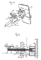
- FIGs 4 to 7 illustrate an embodiment of removable jaws made using a sheet plate bent at right angles, one side F constitutes the application face of the jaw, while the fold R is used for removable fixing of the jaw 12-13 on the actuation shaft 17, 18.
- This attachment involves a stirrup E of U-shaped section produced using a folded sheet metal strip.
- the free ends of the wings 40, 41 of this stirrup E include tabs intended to engage and fix themselves for example by welding in slots 42, 43 made in the fold R parallel to side F.
- the parallel wings 40, 41 of the stirrup E are provided with two coaxial holes T 1 , T 2 in which the end of the shaft 17, 18 engages, which has for this purpose a corresponding diameter.
- the blocking of the shaft 17, 18 is then obtained by means of a pin of positioning P to crimp or screw which includes a socket D in which is screwed a PU needle by means of a knurled head TM.
- the end of socket D opposite the head TM includes a constriction or a thread intended to come to engage in force or to be screwed in a drilling carried out in the fold R at the right of the tree 17, 18.
- the head of the needle screw PU engages in a bore T 3 made previously in the shaft 17, 18 in an appropriate location.
- a PU needle screw it would be possible to use a pawl biased by a spring so as to be able to engage in the bore T 3 or in a circular groove (in the latter case, the jaw will be crazy climb around the tree 17, 18).
- a transparent or non-transparent FT sheet for example made of rubber or plastic material with or without incrustations or reliefs I improving mixing while allowing vision of the bag through window 9 of door 8 (figure 8).
- This interlayer sheet which comes in direct contact with the bags containing the samples may be equipped with heating means and / or cooling.
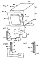
- the mixer first includes a housing 101 of parallelepiped shape elongated along a longitudinal axis.
- This case made for example of stainless steel, is mounted on pads absorbing vibrations 102. It comprises an upper face 103, a face lower 104, two lateral faces 105, 106 and a bottom 107.
- the front face is constituted by a door 108 articulated around an axis A / A 'on the bottom around a horizontal axis.
- Door 108 could just as well swing around a vertical axis secured to one side side 105, 106 of the housing.
- the door 108 has in its central part a double wall P 1 , P 2 delimiting a volume V in which a heat transfer fluid can flow from a fluid circuit connected to an inlet nozzle BA and to a nozzle back BR.
- This heat transfer fluid may consist, for example, of water coming from a water circuit.
- the temperature of the sample submitted to the mixer will be maintained at a temperature close to the water temperature.
- the coolant temperature is set to a value of adjustable setpoint thanks to a CT control circuit which measures the deviation between the setpoint temperature TC and the temperature of the cooling measured by an ST temperature probe immersed in the tank CU, and which controls the primary cooling circuit CP of so as to reduce this deviation to zero.
- Volume V may also contain in addition to or in replacement of the coolant, solid or temperature regulating wax.
- the door could be fitted with an effect cell Peltier PE controlled by an electronic regulation circuit CER receiving a information of the temperature of the wall of the door on which comes in press the bag containing the sample, this temperature being measured by a DT sensor in thermal contact with the interior wall PI of door P.
- an electronic regulation circuit CER receiving a information of the temperature of the wall of the door on which comes in press the bag containing the sample, this temperature being measured by a DT sensor in thermal contact with the interior wall PI of door P.
- the rear articulation of the door could be disconnectable so as to be able to equip the mixer with a door 108 corresponding to its needs (heating / cooling / maintaining at ambient temperature, etc.).
- connection head TD has a parallelepiped shape, one of the longitudinal faces FL 1 of which has a series of transverse slots ET 1 , ET 2 , ET 3 , while a series of transverse holes P 1 to P 3 is produced in the vicinity of the longitudinal face FL 2 situated opposite the face FL 1 , these holes P 1 to P 3 being spaced from each other by a distance equal to the distance separating the notches AND 1 to AND 3
- the two wings AL 1 , AL 2 are provided with two pairs of coaxial holes, namely, a pair of holes P 5 , P 6 in which the ends of a connecting rod TL and a pair of holes P 7 , P 8 into which a key CL can engage, the distance between the rod TL and the key CL corresponding to the distance separating the bottom of the slots ET 1 to ET 3 to the corresponding holes P 1 to P 3 .
- connection head TD The attachment of the jaw 12 "on the connection head TD is then obtained by engaging the rod TL in one of the slots ET 1 to ET 3 , then after having brought the pair of holes P 7 , P 8 coaxially to the holes P 1 to P 3 corresponding to this notch, by engaging the key in said holes.
- the machine 12 "' is integral with a structure ST on which is rotatably mounted a nut EC 1 into which the threaded end of the actuating rod 17" is screwed.
- This nut EC 1 which is retained axially on the structure ST therefore allows adjustment in the axial position of the jaw 12 "'.
- the rod 17 "' is slidably mounted in a slide tube TG passing through a bore PE 1 of the front face 14 of the housing 10 and whose end, located on the jaw side 12", abuts on an adjusting nut EC 2 prestressing screwed onto a threaded portion of the 17 '''rod.
- the actuation of the rod 17 "'from a BT rod driven by the crankshaft 21 is ensured by means of a pusher PS produced by means of a metal part in the shape of a U, the two vertical wings AV 1 , AV 2 have two coaxial holes PE 2 , PE 3 .
- a helical damping spring RH coaxial with the rod 17 "'.
- This spring RH is subjected to a adjustable preload by screwing or unscrewing the nut EC 2 which causes an axial displacement of the tube TG relative to the pusher PS and therefore compression or loosening of the spring RH.
- the nut EC 1 (Allen type) accessible through the central part of the front face of the jaw 12 "', leaves, by turning, varying the distance in addition to the jaw 12"' and the door 8 "'of the mixer, the rotation of the jaw 12 '''around its axis being avoided by a rotation locking rod TB secured to the jaw 12 "' which extends parallel to the rod 17"'and passes through a PE 4 hole of the face 14 of the housing 10.
Landscapes
- Chemical & Material Sciences (AREA)
- Chemical Kinetics & Catalysis (AREA)
- Mixers With Rotating Receptacles And Mixers With Vibration Mechanisms (AREA)
- Sampling And Sample Adjustment (AREA)
- Investigating Or Analysing Biological Materials (AREA)
Claims (26)
- Knetmaschine für die Vorbereitung von Proben für die Durchführung von Analysen und/oder Tests, wobei diese Knetmaschine Auflagevorrichtungen (8) beinhaltet, gegen die ein Beutel (16) mit einer Probe anhand von mindestens einer Backe (12, 13) gedrückt wird, die rechtwinklig im Verhältnis zu der Auflagevorrichtung (8) beweglich ist, und dies anhand einer hin- und hergehenden Bewegung, um den Beutel gegen die Auflagevorrichtung zu klopfen, und eine feststehende Tragkonstruktion (1)
dadurch gekennzeichnet, dass sie zwei Strukturen beinhaltet, die im Verhältnis zueinander beweglich sind, nämlich:die genannte feststehende Tragkonstruktion (1),eine bewegliche, starre oder verformbare Struktur (10), die anhand der feststehenden Struktur (1) in der Weise geführt wird, dass sie sich im Verhältnis zu den Auflagevorrichtungen bewegen kann, wobei diese bewegliche Struktur die Backe (12, 13) sowie deren Betätigungsmechanismus und Mittel für die Verriegelung/Entriegelung in Position (25, 26, 27) der beweglichen Struktur (10) auf der feststehenden Struktur (1) beinhaltet. - Knetmaschine gemäß Patentanspruch 1,
dadurch gekennzeichnet, dass die. genannte Backe (12, 13) anhand einer elastischen Verbindung (22, 23) und gegebenenfalls in Verbindung mit Dämpfüngsmitteln auf dem Betätigungsmechanismus montiert ist. - Knetmaschine gemäß Patentanspruch 2,
dadurch gekennzeichnet, dass die Backe (12, 13) eine Vorderseite besitzt, die sägezahnförmige Rippen (15) aufweist. - Knetmaschine gemäß einem der vorangegangenen Patentansprüche,
dadurch gekennzeichnet, dass die oben genannte Backe (12, 13) auf dem Wege über eventuell trennbare Befestigungsmittel feststehend auf einer Betätigungswelle (17, 18) montiert ist. - Knetmaschine gemäß Patentanspruch 1 bis 3,
dadurch gekennzeichnet, dass die oben genannte Backe (12, 13) locker auf ihrer Betätigungswelle montiert ist (um den Kneteffekt zu verbessern). - Knetmaschine gemäß Patentanspruch 4,
dadurch gekennzeichnet, dass die oben genannten Befestigungsmittel einen Bügel (E) beinhalten, der auf der Backe (12, 13) montiert ist und dessen beide gegenüberliegenden Flügel (40, 42) mit koaxialen Bohrungen (T1, T2) ausgerüstet sind, in welche das Ende der Betätigungswelle (17, 18) eingreift. - Knetmaschine gemäß Patentanspruch 6,
dadurch gekennzeichnet, dass der genannte Bügel (E) auf einem Teil der Backe (12, 13) montiert ist, die rechtwinklig umgebogen ist. - Knetmaschine gemäß Patentanspruch 4,
dadurch gekennzeichnet, dass die lösbaren Mittel für die Befestigung eine Schraube mit spitzem Ende (POU) oder eine Klinke beinhalten, die in eine Bohrung (T3) oder in eine Nut in der Betätigungswelle (17, 18) eingreift. - Knetmaschine gemäß einem der Patentansprüche 1 bis 3,
dadurch gekennzeichnet, dass die Backe (12, 13) auf der Betätigungswelle (17, 18) gelenkig gelagert ist. - Knetmaschine gemäß Patentanspruch 9,
dadurch gekennzeichnet, dass die Backe (12, 13) auf der feststehenden Struktur (1) gelenkig gelagert ist. - Knetmaschine gemäß einem der Patentansprüche 9 und 10,
dadurch gekennzeichnet, dass die Backe (12, 13) in Höhe eines ihrer Ränder am Ende einer Achse (38) gelenkig gelagert ist, die verschiebbar auf der feststehenden Struktur (1) montiert ist und anhand der elastischen Mittel (42) beansprucht wird. - Knetmaschine gemäß einem der vorangegangenen Patentansprüche,
dadurch gekennzeichnet, dass die feststehende Struktur aus einem ersten Gehäuse in Form eines Parallelepipedons (1) besteht, dessen Vorderseite eine Klappe (8) aufweist, die auf dem Gehäuse (1) um eine senkrechte oder waagerechte Achse (A/A') herum gelenkig gelagert ist und die die genannten Auflagevorrichtungen bildet, und dadurch, dass die bewegliche Struktur aus einem Gehäuse (19) oder einer Platte besteht, die den Betätigungsmechanismus der Backe (12, 13) trägt, wobei dieses zweite Gehäuse (10) oder diese Platte in Längsrichtung im ersten Gehäuse (1) beweglich ist und in letzterem anhand der Blockiervorrichtungen (25, 26) blockiert werden kann, die eine der Seitenwände (3) des ersten Gehäuses (1) durchqueren. - Knetmaschine gemäß Patentanspruch 12,
dadurch gekennzeichnet, dass sie Verriegelungsmittel (30, 31, 32) für die Klappe (8) beinhaltet, die die Versorgung der Knetmaschine mit elektrischem Strom steuern. - Knetmaschine gemäß einem der vorangegangenen Patentansprüche,
dadurch gekennzeichnet. dass zwischen den genannten Auflagevorrichtungen (8) und der genannte Backe (12, 13) ein transparentes oder nicht transparentes Blatt (FT) angeordnet ist, das Vertiefungen (1) oder Reliefs aufweist, die das Kneten verbessern und gleichzeitig die Sicht auf den Beutel durch das Fenster (9) in den Auflagevorrichtungen (9) ermöglichen. - Knetmaschine gemäß einem der vorangegangenen Patentansprüche,
dadurch gekennzeichnet, dass den oben genannten Backen (12, 13) und/oder den oben genannten Auflagevorrichtungen (8) Heiz- und/oder Kühlvorrichtungen und/oder Vorrichtungen für das Halten der Temperatur der Beutel mit den zu analysierenden Proben zugeordnet sind. - Knetmaschine gemäß Patentanspruch 15,
dadurch gekennzeichnet, dass die oben genannten Heiz- und/oder Kühlvorrichtungen und/oder Vorrichtungen für das Halten der Temperatur einen Wärmetauscher (P1, P2) beinhalten, in dem eine Kühlflüssigkeit zirkuliert. - Knetmaschine gemäß Patentanspruch 16,
dadurch gekennzeichnet, dass die oben genannte Kühlflüssigkeit aus Wasser besteht, das aus einem Verteilerkreislauf stammt. - Knetmaschine gemäß Patentanspruch 16,
dadurch gekennzeichnet, dass die oben genannte Kühlflüssigkeit eine Flüssigkeit ist, die aus einem Sekundärkühlreis stammt, der thermisch an einen Primärkühlreis (CP) gekoppelt ist. - Knetmaschine gemäß einem der Patentansprüche 15 bis 18,
dadurch gekennzeichnet, dass die genannten Heizmittel Heizwiderstände (REC) beinhalten, die in die oben genannten Auflagevorrichtungen (8) integriert sind. - Knetmaschine gemäß Patentanspruch 15,
dadurch gekennzeichnet, dass die oben genannten Kühlvorrichtungen aus Peltier-Elementen (PE) bestehen. - Knetmaschine gemäß einem der voranstehenden Patentansprüche,
dadurch gekennzeichnet, dass sie ein Gehäuse beinhaltet, das eine Zerkleinerungskammer und eine technische Kammer und Auflagevorrichtungen beinhaltet, die aus einer Klappe (108) und einer Fensterklappe für den Zugang zur Zerkleinerungskammer bestehen, wobei die Vorrichtungen für das Beheizen und/oder Kühlen und/oder Halten der Temperatur in die oben genannten Klappe (108) integriert sind. - Knetmaschine gemäß Patentanspruch 21,
dadurch gekennzeichnet, dass die Klappe eine Doppelwandung (P1, P2) aufweist, die einen Raum (V) begrenzt, in dem eine Kühlflüssigkeit zirkulieren kann und/oder die einen Feststoff oder ein Wachs mit einer temperaturregelnden Wirkung enthält. - Knetmaschine gemäß Patentanspruch 14,
dadurch gekennzeichnet, dass die oben genannte Zwischenlage mit Vorrichtungen zum Heizen und/oder Abkühlen ausgerüstet ist. - Knetmaschine gemäß Patentanspruch 4,
dadurch gekennzeichnet, dass die einstellbare Befestigung der Backe (12") auf ihrer Betätigungswelle (17") anhand einer trennbaren Verbindung erreicht wird, die einerseits einen Verbindungskopf (TC) beinhaltet, der fest mit der Betätigungswelle (17") verbunden ist, eine Serie von Einschnitten in Querrichtung (ET1, ET2, ET3) sowie eine Reihe von Bohrungen (P1 bis P3), und andererseits eine Kappe, die fest mit der Backe (12") verbunden ist und deren beide parallelen Flügel anhand eines Verbindungsstabs (TL) miteinander verbunden sind, der dazu dient, um in einen Einschnitt (ET1 bis ET3) einzugreifen und zwei koaxiale Bohrungen (P7, P8) aufweist, die mit einer der genannten Bohrungen (P1 bis P3) des Kopfes (TD) zusammenwirken und dafür vorgesehen sind, um einen Stift aufzunehmen, der die genannte Bohrung passiert. - Knetmaschine gemäß Patentanspruch 4,
dadurch gekennzeichnet, dass:die Backe (12''') fest mit einer Struktur (ST) verbunden ist, auf der rotierend eine Mutter (EC1) montiert ist, in die ein Gewindeende des Betätigungsstabs (17''') eingeschraubt wird,der Stab (17''') verschiebbar in einem Gleitrohr (TG) montiert ist, das verschiebbar auf der feststehenden Struktur des Gehäuses angebracht ist und dessen eines Ende zur Seite der Backe (12''') hin gegen eine Einstellschraube EC2 drückt, die mit Vorspannung auf einen Gewindeabschnitt des Stabs (13''') aufgeschraubt ist.die Betätigung des Stabs (17''') anhand einer elastischen Verbindung gewährleistet wird, deren Vorspannung anhand des Aufschraubens oder Abschraubens der genannten Einstellmutter (EC2) einstellbar ist. - Knetmaschine gemäß Patentanspruch 25,
dadurch gekennzeichnet, dass die oben genannte elastische Verbindung einen Stößel (PS) in Form eines U beinhaltet, dessen beide senkrechten Flügel (AV1, AV2) mit zwei koaxialen Bohrungen versehen sind, in denen jeweils das Ende des Stabs (12''') und des Gleitrohrs (TG) gleiten, wobei das genannte Ende einen Absatz (EP) aufweist, der als Endanschlag für die relativen Bewegungen des Stabes (12''') im Verhältnis zum Stößel (PS) dient und dass zwischen dem Ende des Gleitrohrs (TG) gegenüber der Einstellschraube (EC2) und dem senkrechten Flügel (AV1) eine Dämpfungsfeder (RH) angeordnet ist.
Priority Applications (1)
| Application Number | Priority Date | Filing Date | Title |
|---|---|---|---|
| FR9916552A FR2795658B1 (fr) | 1999-06-30 | 1999-12-24 | Malaxeur a action mecanique reglable |
Applications Claiming Priority (4)
| Application Number | Priority Date | Filing Date | Title |
|---|---|---|---|
| FR9808587 | 1998-07-01 | ||
| FR9808587A FR2780786B1 (fr) | 1998-07-01 | 1998-07-01 | Malaxeur pour la preparation d'echantillons, en vue d'effectuer des analyses et/ou des tests |
| FR9809904A FR2781695B1 (fr) | 1998-07-30 | 1998-07-30 | Malaxeur pour la preparation sous temperature controlee d'echantillons en vue de leurs analyses |
| FR9809904 | 1998-07-30 |
Publications (2)
| Publication Number | Publication Date |
|---|---|
| EP0968760A1 EP0968760A1 (de) | 2000-01-05 |
| EP0968760B1 true EP0968760B1 (de) | 2002-12-18 |
Family
ID=26234426
Family Applications (1)
| Application Number | Title | Priority Date | Filing Date |
|---|---|---|---|
| EP99401621A Expired - Lifetime EP0968760B1 (de) | 1998-07-01 | 1999-06-30 | Mischer zur Herstellung von mikrobiologischen Analysen- und/oder Testproben |
Country Status (2)
| Country | Link |
|---|---|
| EP (1) | EP0968760B1 (de) |
| ES (1) | ES2189360T3 (de) |
Families Citing this family (22)
| Publication number | Priority date | Publication date | Assignee | Title |
|---|---|---|---|---|
| US11077020B2 (en) * | 2013-05-07 | 2021-08-03 | Biosafe S.A. | Fluid processing based on inflatable bags, mixing system, and method of use thereof |
| FR3012979B1 (fr) * | 2013-11-14 | 2016-01-01 | Awel | Broyeur de produits enfermes dans des sacs comprenant au moins deux pales pivotantes |
| CN104874321A (zh) * | 2015-05-11 | 2015-09-02 | 成都中牧生物药业有限公司 | 具有控温系统的粉末摇匀装置改进结构 |
| JP7010926B2 (ja) * | 2016-07-28 | 2022-01-26 | バイオファイア・ダイアグノスティクス,リミテッド・ライアビリティ・カンパニー | 自己完結型の核酸処理 |
| CN110312576B (zh) * | 2016-12-19 | 2021-10-29 | 坎布科技有限公司 | 改进的提取设备 |
| CN107054752A (zh) * | 2017-04-08 | 2017-08-18 | 温州智科包装机械有限公司 | 一种zk‑500型多工位全自动给袋机 |
| FR3090407B1 (fr) | 2018-12-21 | 2020-12-04 | Seb Sa | Appareil de fabrication, machine à mélange et/ou dispositif de réception pour la fabrication d’une composition à partir d’un mélange de formulations |
| FR3090405B1 (fr) | 2018-12-21 | 2023-04-28 | Seb Sa | Appareil de fabrication, machine à mélange et/ou dispositif de réception pour la fabrication d’une composition à partir d’un mélange de formulations |
| FR3090406B1 (fr) * | 2018-12-21 | 2020-12-04 | Seb Sa | Appareil de fabrication, machine à mélange et/ou dispositif de réception pour la fabrication d’une composition à partir d’un mélange de formulations |
| FR3090403B1 (fr) * | 2018-12-21 | 2023-03-31 | Seb Sa | Appareil de fabrication, machine à mélange et/ou dispositif de réception pour la fabrication d’une composition à partir d’un mélange de formulations |
| FR3090396B1 (fr) | 2018-12-21 | 2023-03-31 | Seb Sa | Appareil de fabrication, machine à mélange et/ou dispositif de réception pour la fabrication d’une composition à partir d’un mélange de formulations |
| FR3090404B1 (fr) * | 2018-12-21 | 2023-03-31 | Seb Sa | Appareil de fabrication, machine à mélange et/ou dispositif de réception pour la fabrication d’une composition à partir d’un mélange de formulations |
| FR3090400B1 (fr) | 2018-12-21 | 2023-03-31 | Seb Sa | Appareil de fabrication, machine à mélange et/ou dispositif de réception pour la fabrication d’une composition à partir d’un mélange de formulations |
| FR3090397B1 (fr) | 2018-12-21 | 2021-09-17 | Seb Sa | Appareil de fabrication, machine à mélange et/ou dispositif de réception pour la fabrication d’une composition à partir d’un mélange de formulations |
| FR3090402B1 (fr) | 2018-12-21 | 2021-09-17 | Seb Sa | Appareil de fabrication, machine à mélange et/ou dispositif de réception pour la fabrication d’une composition à partir d’un mélange de formulations |
| FR3090408B1 (fr) | 2018-12-21 | 2023-03-31 | Seb Sa | Appareil de fabrication, machine à mélange et/ou dispositif de réception pour la fabrication d’une composition à partir d’un mélange de formulations |
| FR3090399B1 (fr) | 2018-12-21 | 2021-09-17 | Seb Sa | Appareil de fabrication, machine à mélange et/ou dispositif de réception pour la fabrication d’une composition à partir d’un mélange de formulations |
| FR3090398B1 (fr) * | 2018-12-21 | 2021-06-25 | Seb Sa | Appareil de fabrication, machine à mélange et/ou dispositif de réception pour la fabrication d’une composition à partir d’un mélange de formulations |
| FR3090401B1 (fr) | 2018-12-21 | 2023-04-28 | Seb Sa | Appareil de fabrication, machine à mélange et/ou dispositif de réception pour la fabrication d’une composition à partir d’un mélange de formulations |
| GB2586567B (en) * | 2019-03-01 | 2023-10-18 | Asymptote Ltd | Closed tissue disaggregation and cryopreservation |
| KR102926094B1 (ko) * | 2019-03-01 | 2026-02-12 | 바이오세이프 쏘시에떼아노님 | 폐쇄된 조직 분해 및 냉동 보존 |
| GB202017038D0 (en) * | 2020-10-27 | 2020-12-09 | Global Life Sciences Solutions Operations UK Ltd | Apparatus for tissue disaggregation |
Family Cites Families (3)
| Publication number | Priority date | Publication date | Assignee | Title |
|---|---|---|---|---|
| BE788274A (fr) * | 1971-09-06 | 1973-02-28 | Unilever Nv | Dispositifs servant a melanger des matieres |
| JPS6265724A (ja) * | 1985-09-17 | 1987-03-25 | Chiyoda Tech & Ind Co Ltd | 袋詰め混練方法 |
| EP0912237B1 (de) * | 1996-05-13 | 2001-04-18 | Filtaflex Limited | Mit schlaggerät versehender beutelklopfende supendiergerät für mikroben |
-
1999
- 1999-06-30 ES ES99401621T patent/ES2189360T3/es not_active Expired - Lifetime
- 1999-06-30 EP EP99401621A patent/EP0968760B1/de not_active Expired - Lifetime
Also Published As
| Publication number | Publication date |
|---|---|
| EP0968760A1 (de) | 2000-01-05 |
| ES2189360T3 (es) | 2003-07-01 |
Similar Documents
| Publication | Publication Date | Title |
|---|---|---|
| EP0968760B1 (de) | Mischer zur Herstellung von mikrobiologischen Analysen- und/oder Testproben | |
| FR2781695A1 (fr) | Malaxeur pour la preparation sous temperature controlee d'echantillons en vue de leurs analyses | |
| EP0102301A2 (de) | Maschine und Arbeitsweise zum Herstellen von Kunststoffbeuteln mit Reissverschluss und Vorrichtung zum Anbringen desselben | |
| EA014679B1 (ru) | Самофиксирующийся механизм | |
| FR3015933A1 (de) | ||
| WO2007027443A2 (en) | Hair clipper with blade assembly release | |
| EP3345660B1 (de) | Anschlag für fixierungsvorrichtung eines schuhs | |
| FR2795658A1 (fr) | Malaxeur a action mecanique reglable | |
| FR2702563A1 (fr) | Dispositif pour le prélèvement d'échantillons de sols. | |
| FR2838995A3 (fr) | Cle a molette reversible du type a galet | |
| EP0754832B1 (de) | Scharnier für den Gehäusedeckel eines Kochgerätes | |
| CN110455520B (zh) | 瓶盖开合寿命测试装置 | |
| FR3118570A1 (fr) | Poignée amovible munie d’un organe d’appui renforcé | |
| EP0216717A1 (de) | Klemmzange mit selbsteinstellenden Backen | |
| FR2893560A1 (fr) | Vehicule comprenant un siege coulissant escamotable | |
| FR2780786A1 (fr) | Malaxeur pour la preparation d'echantillons, en vue d'effectuer des analyses et/ou des tests | |
| EP0479659A1 (de) | Scheibenwischerarm besonders für Kraftfahrzeuge | |
| EP0514299A1 (de) | Zwischen Schaftmaschine und Webschäfte eingebaute Hebelzugvorrichtung | |
| EP2586940B1 (de) | Verriegelungsvorrichtung eines Öffnungsflügels | |
| FR3057896A1 (fr) | Montage d’une commande d’ouverture de porte du type flush | |
| WO2008071750A1 (fr) | Brucelles a pointes interchangeables | |
| FR2919364A3 (fr) | Dispositif d'embrayage avec fonction anti-panique pour verrous electromecaniques | |
| EP0565436B1 (de) | Wischerarm | |
| BE1017694A3 (fr) | Dispositif de commande pour ustensile de travail, notamment tondeuse a gazon. | |
| FR2766411A1 (fr) | Mecanisme d'impression thermique |
Legal Events
| Date | Code | Title | Description |
|---|---|---|---|
| PUAI | Public reference made under article 153(3) epc to a published international application that has entered the european phase |
Free format text: ORIGINAL CODE: 0009012 |
|
| 17P | Request for examination filed |
Effective date: 19990705 |
|
| AK | Designated contracting states |
Kind code of ref document: A1 Designated state(s): ES FR GB IT |
|
| AX | Request for extension of the european patent |
Free format text: AL;LT;LV;MK;RO;SI |
|
| AKX | Designation fees paid |
Free format text: ES FR GB IT |
|
| REG | Reference to a national code |
Ref country code: DE Ref legal event code: 8566 |
|
| GRAH | Despatch of communication of intention to grant a patent |
Free format text: ORIGINAL CODE: EPIDOS IGRA |
|
| GRAH | Despatch of communication of intention to grant a patent |
Free format text: ORIGINAL CODE: EPIDOS IGRA |
|
| GRAA | (expected) grant |
Free format text: ORIGINAL CODE: 0009210 |
|
| AK | Designated contracting states |
Kind code of ref document: B1 Designated state(s): ES FR GB IT |
|
| REG | Reference to a national code |
Ref country code: GB Ref legal event code: FG4D Free format text: NOT ENGLISH |
|
| GBT | Gb: translation of ep patent filed (gb section 77(6)(a)/1977) |
Effective date: 20030429 |
|
| REG | Reference to a national code |
Ref country code: ES Ref legal event code: FG2A Ref document number: 2189360 Country of ref document: ES Kind code of ref document: T3 |
|
| PLBE | No opposition filed within time limit |
Free format text: ORIGINAL CODE: 0009261 |
|
| STAA | Information on the status of an ep patent application or granted ep patent |
Free format text: STATUS: NO OPPOSITION FILED WITHIN TIME LIMIT |
|
| 26N | No opposition filed |
Effective date: 20030919 |
|
| PGFP | Annual fee paid to national office [announced via postgrant information from national office to epo] |
Ref country code: IT Payment date: 20060630 Year of fee payment: 8 |
|
| PG25 | Lapsed in a contracting state [announced via postgrant information from national office to epo] |
Ref country code: IT Free format text: LAPSE BECAUSE OF NON-PAYMENT OF DUE FEES Effective date: 20070630 |
|
| REG | Reference to a national code |
Ref country code: FR Ref legal event code: PLFP Year of fee payment: 18 |
|
| REG | Reference to a national code |
Ref country code: FR Ref legal event code: PLFP Year of fee payment: 19 |
|
| REG | Reference to a national code |
Ref country code: FR Ref legal event code: PLFP Year of fee payment: 20 |
|
| PGFP | Annual fee paid to national office [announced via postgrant information from national office to epo] |
Ref country code: FR Payment date: 20180605 Year of fee payment: 20 |
|
| PGFP | Annual fee paid to national office [announced via postgrant information from national office to epo] |
Ref country code: ES Payment date: 20180702 Year of fee payment: 20 Ref country code: GB Payment date: 20180418 Year of fee payment: 20 |
|
| REG | Reference to a national code |
Ref country code: GB Ref legal event code: PE20 Expiry date: 20190629 |
|
| PG25 | Lapsed in a contracting state [announced via postgrant information from national office to epo] |
Ref country code: GB Free format text: LAPSE BECAUSE OF EXPIRATION OF PROTECTION Effective date: 20190629 |
|
| REG | Reference to a national code |
Ref country code: ES Ref legal event code: FD2A Effective date: 20201204 |
|
| PG25 | Lapsed in a contracting state [announced via postgrant information from national office to epo] |
Ref country code: ES Free format text: LAPSE BECAUSE OF EXPIRATION OF PROTECTION Effective date: 20190701 |