EP0968798A2 - Motorisch angetriebenes Klammergerät - Google Patents
Motorisch angetriebenes Klammergerät Download PDFInfo
- Publication number
- EP0968798A2 EP0968798A2 EP99250221A EP99250221A EP0968798A2 EP 0968798 A2 EP0968798 A2 EP 0968798A2 EP 99250221 A EP99250221 A EP 99250221A EP 99250221 A EP99250221 A EP 99250221A EP 0968798 A2 EP0968798 A2 EP 0968798A2
- Authority
- EP
- European Patent Office
- Prior art keywords
- staple
- driver
- holding
- parts
- clincher
- Prior art date
- Legal status (The legal status is an assumption and is not a legal conclusion. Google has not performed a legal analysis and makes no representation as to the accuracy of the status listed.)
- Granted
Links
- 230000007246 mechanism Effects 0.000 abstract description 47
- 238000010276 construction Methods 0.000 description 3
- 238000005452 bending Methods 0.000 description 2
- 210000000078 claw Anatomy 0.000 description 2
- 238000001514 detection method Methods 0.000 description 1
- 230000037431 insertion Effects 0.000 description 1
- 238000003780 insertion Methods 0.000 description 1
- 125000006850 spacer group Chemical group 0.000 description 1
Images
















Classifications
-
- B—PERFORMING OPERATIONS; TRANSPORTING
- B27—WORKING OR PRESERVING WOOD OR SIMILAR MATERIAL; NAILING OR STAPLING MACHINES IN GENERAL
- B27F—DOVETAILED WORK; TENONS; SLOTTING MACHINES FOR WOOD OR SIMILAR MATERIAL; NAILING OR STAPLING MACHINES
- B27F7/00—Nailing or stapling; Nailed or stapled work
- B27F7/17—Stapling machines
- B27F7/38—Staple feeding devices
-
- B—PERFORMING OPERATIONS; TRANSPORTING
- B27—WORKING OR PRESERVING WOOD OR SIMILAR MATERIAL; NAILING OR STAPLING MACHINES IN GENERAL
- B27F—DOVETAILED WORK; TENONS; SLOTTING MACHINES FOR WOOD OR SIMILAR MATERIAL; NAILING OR STAPLING MACHINES
- B27F7/00—Nailing or stapling; Nailed or stapled work
- B27F7/17—Stapling machines
- B27F7/19—Stapling machines with provision for bending the ends of the staples on to the work
Definitions
- the present invention relates to a motor driven stapler having a driver unit provided with a driving member for driving out a stapler, and a clincher unit provided with a clinching member for clinching the legs of a staple.
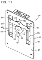
- a motor driven stapler 10 incorporated into, for example, a copying machine has a driver unit 11 and a clincher unit 100.
- the driver unit 11 is movable in the directions of the arrow P1 along a guide rail, not shown.
- the clincher unit 100 is movable in the directions of the arrows P1 along a guide rail, not shown.
- the copying machine delivers a pile Q of sheets in the direction of the arrow P2.
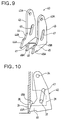
- the anvil 40 has a pair of side plates 42 and 43, and a connecting plate 41 connecting the side plates 42 and 43. Lower parts of the side plates 42 and 43 are projected to the left, as viewed in Fig. 9, to form guide parts 44 and 45. Inclined faces 44A and 45A are formed in free end parts of the guide parts 44 and 45. Flat steps 44B and 45B extend from the upper ends of the inclined faces 44A and 45A.
- a guide part 48 having an inclined face 48A is disposed between the side plates 42 and 43. The inclined faces 44A, 45A and 48A are included in a single plane.
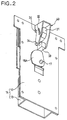
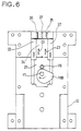
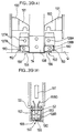
- the guide part 181 has an inclined face 183 for guiding the leg of the staple driven through the pile of sheets toward the clinching plate 138.
- a projection 184 is formed on one side of the clincher guide 180 so as to be brought into contact with a corner of the front end of the clinching plate 138.
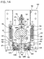
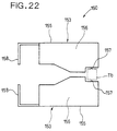
- the clincher guides 180 are biased by springs S3 so that the guide parts 181 are forced into the space between the holding parts 156 of the holding member 153, and the space between the holding parts 166 of the holding member 163, respectively.
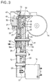
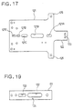
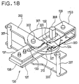
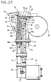
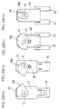
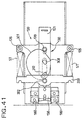
- a protrusion 312 is formed on a side surface 311 of the drive cam 301. As shown in Fig. 18, the protrusion 312 has an inclined face 312A and a triangular cross section. As shown in Fig. 25, an elastic stopper 320 is spaced from the inner surface of the base plate 121 by a spacer 313 and is fixedly held on the inner surface of the base plate 121. The stopper 320 can elastically be warped as shown in Fig. 18.
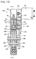
- the drive shaft 308 turns the drive cam 301.
- the drive cam 301 pushes the rod 202 connected to the arm members 200 downward as the same is turned.
- the arm members 200 are moved downward together with the rod 202 relative to the housing 103 to move the clinching device 120 downward.
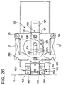
- the photosensor H2 detects the cut 351 of the rotating plate 350, and then the drive motor 307 is stopped.
Landscapes
- Engineering & Computer Science (AREA)
- Mechanical Engineering (AREA)
- Life Sciences & Earth Sciences (AREA)
- Forests & Forestry (AREA)
- Dovetailed Work, And Nailing Machines And Stapling Machines For Wood (AREA)
- Portable Nailing Machines And Staplers (AREA)
- Folding Of Thin Sheet-Like Materials, Special Discharging Devices, And Others (AREA)
Applications Claiming Priority (2)
| Application Number | Priority Date | Filing Date | Title |
|---|---|---|---|
| JP18930098 | 1998-07-03 | ||
| JP18930098 | 1998-07-03 |
Publications (3)
| Publication Number | Publication Date |
|---|---|
| EP0968798A2 true EP0968798A2 (de) | 2000-01-05 |
| EP0968798A3 EP0968798A3 (de) | 2003-03-19 |
| EP0968798B1 EP0968798B1 (de) | 2005-09-28 |
Family
ID=16239034
Family Applications (1)
| Application Number | Title | Priority Date | Filing Date |
|---|---|---|---|
| EP99250221A Expired - Lifetime EP0968798B1 (de) | 1998-07-03 | 1999-07-02 | Motorisch angetriebenes Klammergerät |
Country Status (3)
| Country | Link |
|---|---|
| US (1) | US6164513A (de) |
| EP (1) | EP0968798B1 (de) |
| DE (1) | DE69927437T2 (de) |
Cited By (3)
| Publication number | Priority date | Publication date | Assignee | Title |
|---|---|---|---|---|
| WO2003045645A1 (en) * | 2001-11-29 | 2003-06-05 | Max Co., Ltd. | Electric stapler |
| EP1932638A4 (de) * | 2005-10-04 | 2010-10-20 | Max Co Ltd | Elektrische heftmaschine |
| US7913378B2 (en) | 2006-03-22 | 2011-03-29 | Heidelberger Druckmaschinen Ag | Wire stitcher having a stitching head for processing annular-eyelet staples |
Families Citing this family (17)
| Publication number | Priority date | Publication date | Assignee | Title |
|---|---|---|---|---|
| US6250532B1 (en) * | 1991-10-18 | 2001-06-26 | United States Surgical Corporation | Surgical stapling apparatus |
| DE69805245T2 (de) * | 1997-07-22 | 2003-02-06 | Max Co. Ltd., Tokio/Tokyo | Heftvorrichtung |
| US6634536B2 (en) * | 1999-12-28 | 2003-10-21 | Max Co., Ltd. | Electric stapler |
| JP2002355803A (ja) * | 2001-05-31 | 2002-12-10 | Nisca Corp | ステープル装置 |
| SE0200936L (sv) * | 2002-03-27 | 2003-02-11 | Isaberg Rapid Ab | Klammerformningsarrangemang med benfångarorgan som förhindrar återfjädring av den bockade klammerns ben |
| JP4078924B2 (ja) * | 2002-08-30 | 2008-04-23 | マックス株式会社 | 電動ステープラー |
| JP3955251B2 (ja) * | 2002-09-30 | 2007-08-08 | 松下電器産業株式会社 | ステープラ |
| US6772930B2 (en) * | 2002-11-01 | 2004-08-10 | L&P Property Management Company | Stapler for flaring staple |
| JP4269661B2 (ja) * | 2002-11-26 | 2009-05-27 | マックス株式会社 | 電動ステープラー |
| US7111378B2 (en) * | 2003-08-20 | 2006-09-26 | Hewlett-Packard Development Company, L.P. | Fastener closing |
| US7093339B2 (en) | 2003-08-20 | 2006-08-22 | Hewlett-Packard Development Company, L.P. | Media fastening |
| EP1683616B1 (de) * | 2003-10-20 | 2010-09-15 | Max Co., Ltd. | Schneideinheit für hefter |
| WO2005068135A1 (ja) * | 2004-01-13 | 2005-07-28 | Max Co., Ltd. | ステープラー |
| WO2005097424A2 (en) * | 2004-04-02 | 2005-10-20 | Acco Brands, Inc. | Stapler with inside leg support |
| US7311236B2 (en) * | 2005-04-25 | 2007-12-25 | Tsi Manufacturing Llc | Electric stapler having two anvil plates and workpiece sensing controller |
| US9987734B2 (en) | 2013-01-23 | 2018-06-05 | Worktools, Inc. | Flat clinch anvil assembly |
| US9592597B2 (en) | 2013-01-23 | 2017-03-14 | Worktools, Inc. | Flat clinch stapler anvil assembly |
Family Cites Families (16)
| Publication number | Priority date | Publication date | Assignee | Title |
|---|---|---|---|---|
| US1169339A (en) * | 1915-06-30 | 1916-01-25 | Boston Wire Stitcher Co | Stapling-machine. |
| US2185518A (en) * | 1938-05-23 | 1940-01-02 | Emanuel R Posnack | Stapling device and method |
| US2374770A (en) * | 1940-05-25 | 1945-05-01 | Vickers Armstrongs Ltd | Wire-stitching machine |
| US2320703A (en) * | 1941-06-16 | 1943-06-01 | Boston Wire Stitcher Co | Wire-stitching machine |
| US2469054A (en) * | 1945-11-19 | 1949-05-03 | Internat Staple And Machine Co | Stapling machine |
| US2845626A (en) * | 1955-11-09 | 1958-08-05 | Bocil Corp | Stapling apparatus |
| US3504837A (en) * | 1968-04-24 | 1970-04-07 | Werner Schafroth | Stapling machine and method of forming staples |
| US3807619A (en) * | 1972-06-05 | 1974-04-30 | Fastener Corp | Apparatus for driving staples |
| US4364507A (en) * | 1981-03-23 | 1982-12-21 | Savino Dominick J | Variable closure surgical stapling apparatus with retractable anvil |
| US4593847A (en) * | 1985-05-01 | 1986-06-10 | Interlake, Inc. | Bypass clincher for stitching machine |
| US4623082A (en) * | 1985-05-14 | 1986-11-18 | Max Co. Ltd. | Electronic stapler |
| US4708277A (en) * | 1986-11-28 | 1987-11-24 | Am International Incorporated | Stitching head |
| EP0322906B1 (de) * | 1987-12-28 | 1994-08-17 | Max Co., Ltd. | Elektrischer Heftapparat |
| US5080274A (en) * | 1990-11-01 | 1992-01-14 | Eastman Kodak Company | Stapler head having wire path defining cover |
| US5413266A (en) * | 1991-09-17 | 1995-05-09 | Acco Usa, Inc. | Compact gear arm powered stapler with movable anvil |
| US6059504A (en) * | 1997-07-03 | 2000-05-09 | Max Co., Ltd. | Binding device |
-
1999
- 1999-07-02 US US09/347,511 patent/US6164513A/en not_active Expired - Lifetime
- 1999-07-02 DE DE69927437T patent/DE69927437T2/de not_active Expired - Lifetime
- 1999-07-02 EP EP99250221A patent/EP0968798B1/de not_active Expired - Lifetime
Cited By (13)
| Publication number | Priority date | Publication date | Assignee | Title |
|---|---|---|---|---|
| WO2003045645A1 (en) * | 2001-11-29 | 2003-06-05 | Max Co., Ltd. | Electric stapler |
| US7083073B2 (en) | 2001-11-29 | 2006-08-01 | Max Co., Ltd. | Electric stapler |
| US7191928B2 (en) | 2001-11-29 | 2007-03-20 | Max Co., Ltd. | Electric stapler |
| US7210608B2 (en) | 2001-11-29 | 2007-05-01 | Max Co., Ltd. | Electric stapler |
| US7222771B2 (en) | 2001-11-29 | 2007-05-29 | Max Co., Ltd. | Electric stapler |
| US7222769B2 (en) | 2001-11-29 | 2007-05-29 | Max Co., Ltd. | Electric stapler |
| US7222770B2 (en) | 2001-11-29 | 2007-05-29 | Max Co., Ltd. | Electric stapler |
| US7222766B2 (en) | 2001-11-29 | 2007-05-29 | Max Co., Ltd. | Electric stapler |
| US7311237B2 (en) | 2001-11-29 | 2007-12-25 | Max Co., Ltd. | Electric stapler |
| US7314156B2 (en) | 2001-11-29 | 2008-01-01 | Max Co., Ltd. | Electric stapler |
| EP2116343A3 (de) * | 2001-11-29 | 2009-12-02 | Max Co., Ltd. | Elektrischer Hefter |
| EP1932638A4 (de) * | 2005-10-04 | 2010-10-20 | Max Co Ltd | Elektrische heftmaschine |
| US7913378B2 (en) | 2006-03-22 | 2011-03-29 | Heidelberger Druckmaschinen Ag | Wire stitcher having a stitching head for processing annular-eyelet staples |
Also Published As
| Publication number | Publication date |
|---|---|
| US6164513A (en) | 2000-12-26 |
| EP0968798A3 (de) | 2003-03-19 |
| EP0968798B1 (de) | 2005-09-28 |
| DE69927437T2 (de) | 2006-07-13 |
| DE69927437D1 (de) | 2006-02-09 |
Similar Documents
| Publication | Publication Date | Title |
|---|---|---|
| US6164513A (en) | Motor driven stapler with staple leg holding mechanism | |
| US5269451A (en) | Electric stapler with unmovably fixed magazine | |
| EP0612594B1 (de) | Motorisch angetriebenes Klammergerät | |
| US5791543A (en) | Electric stapler | |
| KR20010049727A (ko) | 전동 호치키스 | |
| US8251272B2 (en) | Stapler | |
| KR100709993B1 (ko) | 전동 호치키스 | |
| US7644851B2 (en) | Stapler | |
| EP1166981B1 (de) | Klammergerät | |
| EP1582323B1 (de) | Klammerfussführungsmechanismus | |
| JP4053757B2 (ja) | ステップラー | |
| EP2111957B1 (de) | Klammerzuführmechanismus in einem Klammerapparat | |
| EP2127834B1 (de) | Mechanismus für Positionierung einer Klammervorrichtung eines Hefters | |
| JP3518428B2 (ja) | 電動ステープラ | |
| US7036706B2 (en) | Stapler apparatus | |
| JPS6399904A (ja) | ホツチキスのステ−プル脚切断駆動装置 | |
| JP4232716B2 (ja) | ステープラ用カートリッジ | |
| JP3692881B2 (ja) | 電動ホッチキス | |
| EP0446055A1 (de) | Vorrichtung zum Formen und Eintreiben von Heftklammern | |
| JP2501487Y2 (ja) | 電動ホッチキス | |
| JP2005022079A (ja) | 電動ステープラ | |
| JP3697989B2 (ja) | 電動ホッチキス | |
| JP2727169B2 (ja) | ステープラー | |
| JP2001191265A (ja) | 電動式ステープラー | |
| JP3692878B2 (ja) | 電動ホチキス |
Legal Events
| Date | Code | Title | Description |
|---|---|---|---|
| PUAI | Public reference made under article 153(3) epc to a published international application that has entered the european phase |
Free format text: ORIGINAL CODE: 0009012 |
|
| AK | Designated contracting states |
Kind code of ref document: A2 Designated state(s): AT BE CH CY DE DK ES FI FR GB GR IE IT LI LU MC NL PT SE |
|
| AX | Request for extension of the european patent |
Free format text: AL;LT;LV;MK;RO;SI |
|
| PUAL | Search report despatched |
Free format text: ORIGINAL CODE: 0009013 |
|
| AK | Designated contracting states |
Kind code of ref document: A3 Designated state(s): AT BE CH CY DE DK ES FI FR GB GR IE IT LI LU MC NL PT SE |
|
| AX | Request for extension of the european patent |
Extension state: AL LT LV MK RO SI |
|
| 17P | Request for examination filed |
Effective date: 20030725 |
|
| AKX | Designation fees paid |
Designated state(s): DE FR GB NL SE |
|
| 17Q | First examination report despatched |
Effective date: 20040204 |
|
| GRAP | Despatch of communication of intention to grant a patent |
Free format text: ORIGINAL CODE: EPIDOSNIGR1 |
|
| GRAS | Grant fee paid |
Free format text: ORIGINAL CODE: EPIDOSNIGR3 |
|
| GRAA | (expected) grant |
Free format text: ORIGINAL CODE: 0009210 |
|
| AK | Designated contracting states |
Kind code of ref document: B1 Designated state(s): DE FR GB NL SE |
|
| REG | Reference to a national code |
Ref country code: GB Ref legal event code: FG4D |
|
| REG | Reference to a national code |
Ref country code: SE Ref legal event code: TRGR |
|
| REF | Corresponds to: |
Ref document number: 69927437 Country of ref document: DE Date of ref document: 20060209 Kind code of ref document: P |
|
| ET | Fr: translation filed | ||
| PLBE | No opposition filed within time limit |
Free format text: ORIGINAL CODE: 0009261 |
|
| STAA | Information on the status of an ep patent application or granted ep patent |
Free format text: STATUS: NO OPPOSITION FILED WITHIN TIME LIMIT |
|
| 26N | No opposition filed |
Effective date: 20060629 |
|
| PGFP | Annual fee paid to national office [announced via postgrant information from national office to epo] |
Ref country code: FR Payment date: 20140708 Year of fee payment: 16 Ref country code: GB Payment date: 20140702 Year of fee payment: 16 |
|
| GBPC | Gb: european patent ceased through non-payment of renewal fee |
Effective date: 20150702 |
|
| PG25 | Lapsed in a contracting state [announced via postgrant information from national office to epo] |
Ref country code: GB Free format text: LAPSE BECAUSE OF NON-PAYMENT OF DUE FEES Effective date: 20150702 |
|
| REG | Reference to a national code |
Ref country code: FR Ref legal event code: ST Effective date: 20160331 |
|
| PG25 | Lapsed in a contracting state [announced via postgrant information from national office to epo] |
Ref country code: FR Free format text: LAPSE BECAUSE OF NON-PAYMENT OF DUE FEES Effective date: 20150731 |
|
| PGFP | Annual fee paid to national office [announced via postgrant information from national office to epo] |
Ref country code: NL Payment date: 20170614 Year of fee payment: 19 |
|
| PGFP | Annual fee paid to national office [announced via postgrant information from national office to epo] |
Ref country code: DE Payment date: 20170627 Year of fee payment: 19 |
|
| PGFP | Annual fee paid to national office [announced via postgrant information from national office to epo] |
Ref country code: SE Payment date: 20170711 Year of fee payment: 19 |
|
| REG | Reference to a national code |
Ref country code: DE Ref legal event code: R119 Ref document number: 69927437 Country of ref document: DE |
|
| REG | Reference to a national code |
Ref country code: NL Ref legal event code: MM Effective date: 20180801 |
|
| PG25 | Lapsed in a contracting state [announced via postgrant information from national office to epo] |
Ref country code: DE Free format text: LAPSE BECAUSE OF NON-PAYMENT OF DUE FEES Effective date: 20190201 |
|
| PG25 | Lapsed in a contracting state [announced via postgrant information from national office to epo] |
Ref country code: SE Free format text: LAPSE BECAUSE OF NON-PAYMENT OF DUE FEES Effective date: 20180703 Ref country code: NL Free format text: LAPSE BECAUSE OF NON-PAYMENT OF DUE FEES Effective date: 20180801 |