EP0968846A2 - Luftreifen, Verfahren zu seiner Herstellung und Vulkanisierform für ein Luftreifen Herstellungsverfahren - Google Patents
Luftreifen, Verfahren zu seiner Herstellung und Vulkanisierform für ein Luftreifen Herstellungsverfahren Download PDFInfo
- Publication number
- EP0968846A2 EP0968846A2 EP99305000A EP99305000A EP0968846A2 EP 0968846 A2 EP0968846 A2 EP 0968846A2 EP 99305000 A EP99305000 A EP 99305000A EP 99305000 A EP99305000 A EP 99305000A EP 0968846 A2 EP0968846 A2 EP 0968846A2
- Authority
- EP
- European Patent Office
- Prior art keywords
- tyre
- bead
- forming
- tread
- sidewall
- Prior art date
- Legal status (The legal status is an assumption and is not a legal conclusion. Google has not performed a legal analysis and makes no representation as to the accuracy of the status listed.)
- Granted
Links
Images


Classifications
-
- B—PERFORMING OPERATIONS; TRANSPORTING
- B60—VEHICLES IN GENERAL
- B60C—VEHICLE TYRES; TYRE INFLATION; TYRE CHANGING; CONNECTING VALVES TO INFLATABLE ELASTIC BODIES IN GENERAL; DEVICES OR ARRANGEMENTS RELATED TO TYRES
- B60C3/00—Tyres characterised by the transverse section
Definitions
- the present invention relates to a pneumatic tyre, a producing method thereof and a tyre vulcanising mould used for the producing method of the pneumatic tyre, capable of suppressing disturbance of the carcass cord arrangement generated when a green tyre is vulcanised and formed, and improving the uniformity.
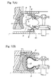
- a green tyre (t1) made on a forming drum is vulcanised and formed in a tyre vulcanising mould (b), thereby making a finished tyre (t2) having final a shape very close to the tyre outline shape when assembled onto a rim as shown in Figs. 7(A) and 7(B).
- a compression force (x) which becomes greatest when the bead cores (d1) pass through the sidewall maximum width positions (p) is temporarily applied to the carcass (e).
- a disturbance of the cord arrangement such as a meander (k) is generated in the carcass cords (e1), and this is a cause of deterioration in the uniformity which results in increased tyre noise and lowering of the steering stability of the vehicle.
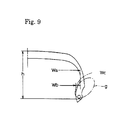
- Wc is designated as the difference between the axial distance Wa of the tyre inner peripheral surface and the distance Wb of the bead portion inner surface, both from the tyre centreline, and h is the height of the tyre cross-section then a bead offset ratio can be set as Wc/h.
- this was set at 0.2 or smaller whereas in normal tyres it is typically 0.5.
- a pneumatic tyre comprises a bead core in a bead portion, and a carcass extending from a tread portion to said bead core of said bead portion through a sidewall portion, wherein a tyre inner surface in a tyre meridian cross-section is in a substantially spread form inward in the tyre's radial direction in its region from said tread portion to said bead portion through said sidewall portion.
- a method of producing a pneumatic tyre comprises the steps of vulcanising a green tyre provided at its bead portion with a bead core, using a vulcanising mould having a shape in which a tyre inner surface in a tyre meridian cross-section when said green tyre is mounted and pressurised by a bladder substantially spreads inward in the tyre's radial direction in its region from a tread portion to a bead portion through a sidewall portion.
- a tyre vulcanising mould comprises a tyre forming surface having a substantially spread shape inwardly in the tyre's radial direction in its region from a tread forming surface portion forming an outer surface of a tread portion to a bead forming surface portion forming an outer surface of a bead portion through a sidewall forming surface portion forming an outer surface of a sidewall portion, and said tyre forming surface has a maximum width at a bead heel corresponding portion for forming a bead heel.
- the tyre vulcanising mould may have an angle ⁇ which is 85 degrees or smaller, where said angle ⁇ is defined between a tyre axial direction line and a line segment extending from said bead heel corresponding portion through a position of intermediate height of a curved surface of a minimum radius between said tread forming surface portion and said sidewall forming surface portion.
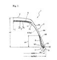
- Fig. 1 is a meridian cross-sectional view of a pneumatic tyre 1 after being vulcanised and formed.
- the pneumatic tyre 1 is a radial tyre for a passenger car, and includes a tread portion 2, a pair of sidewall portions 3 extending from opposite ends of the tread portion 2 in a radially inward direction of the tyre, and bead portions 4 located at the inner ends of the sidewall portions 3.
- a carcass 6 is provided between the bead portions 4, 4 of the pneumatic tyre 1, and the tread portion 2 is reinforced by a belt layer 7 disposed outside the carcass 6 and inside of the tread portion 2.
- the belt layer 7 comprises two or more (two, in the present embodiment) belt plies 7a, 7b whose belt cords are disposed at 30° or less with respect to the tyre equator C, and the belt cords are superposed such that they intersect each other between the plies.
- Steel cord is preferable as the belt cord, but the belt cord may be an organic fibre cord such as nylon, polyester, rayon and aromatic polyamide.
- the belt layer 7 has at its outer side with a band layer 9 for preventing lifting of the belt layer 7.
- the band layer 9 comprises a continuous ply formed by helically winding an organic fibre cord such as nylon substantially parallel to the tyre equator C, and the band layer 9 is formed such as to cover at least an outer edge portion of the belt layer 7.
- the carcass 6 is formed of one or more carcass plies 6a having a ply body 6A extending from the tread portion 2 to the bead portion 4 through the sidewall portion 3 and reaching a bead core 5, and a ply turn-up portion 6B continuously formed with the ply body 6A and folded back from the inner side of the tyre around the bead core 5.
- the carcass ply 6a includes carcass cords disposed at 70 to 90° with respect to the tyre equator C.
- An organic fibre cord such as nylon, polyester, rayon and aromatic polyamide, or a metal fibre cord such as steel is employed as the carcass cord.
- one carcass ply 6a is used comprising an organic fibre cord disposed at substantially 90° with respect to the tyre equator C.
- a bead apex rubber 8 extending from the bead core 5 outwardly in the tyre radial direction is disposed between the ply body 6A and the ply turn-up portion 6B.
- An inner surface and an outer surface of the bead apex rubber 8 in the tyre axial direction contact the ply body 6A and the ply folding portion 6B respectively and or extend substantially parallel to the ply body 6A and the ply folding portion 6B as a reinforcing layer.
- the bead apex rubber 8 has a height H1 from a cross-section centre 5P of the bead core 5 which is 30% or more of a tyre height HT at the cross-section centre 5P, and is made of a hard rubber having a JIS A hardness of 60 to 90 degrees.
- the cross-section of the core has substantially symmetrical shape around its cross-section centre point 5P, i.e., a core having a structure which does not have directivity around the cross-section centre point 5P in terms of strength.
- a core having a structure which does not have directivity around the cross-section centre point 5P in terms of strength.
- various structures of circularly cross-section such as a so-called bunched type in which a large number of filaments are bound together, and a so-called cable type formed with a sheath layer comprising a plurality of sheath wires helically wound around the periphery of the core in the manner a cable.
- an inner liner layer 11 forming a tyre inner barrel, i.e., a tyre inner surface IS is provided between the bead portions 4, 4 along the ply body 6A.
- the tyre inner surface IS is in a substantially spread form inward in the radial direction in its region from the tread portion 2 to the toe tip ends 4A of the bead portions 4 through the sidewall portions 3.
- substantially spread form used in the present application means a shape of an outward inclining state in which the tyre inner surface IS extends substantially obliquely outwards in the tyre axial direction towards the radially inner direction.
- the tyre width Wi between the tyre inner surfaces IS gradually increases in the radially inward direction to form a maximum width Wil between the toe tip ends 4A and 4A.
- the tyre inner surface IS is substantially parallel to the ply body 6A of the carcass 6 and the inner surface of the bead apex rubber 8. Therefore, the inner surfaces of the ply body 6A and the bead apex rubber 8 are also in the substantially spread form.
- the toe tip end 4A corresponds to an inner end of the tyre inner surface IS in the radial direction.
- the bead portion 4 comprises a bead bottom surface portion S1 extending from the toe tip end 4A for sitting on a wheel rim seat, and a flange contact surface portion S3 connected to an outer side of the bead bottom surface portion S1 through a convex arc bead heel S2.
- the tyre outer surface OS is also in a substantially spread form in its region from the tread portion 2 to the bead heel S2 of the bead portion 4 through the sidewall portion 3. Therefore, the tyre width Wo between the tyre outer surfaces OS also gradually increases in the radially inward direction to reach a maximum width Wol between the bead heels S2 and S2.
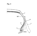
- this pneumatic tyre 1 when this pneumatic tyre 1 is mounted in its standard rim specified by specifications such as JATMA, TRA or ETRTO, the pneumatic tyre 1 assumes a conventional tyre shape, wherein the tyre maximum width WT is provided at a substantially intermediate portion of the sidewall portion 3, and the bead portion 4 is disposed axially inside the maximum width position P.
- the pneumatic tyre 1 is in the substantially spread form close to the green tyre, which is vulcanised. Therefore, in the vulcanising and formation process, the carcass 6 does not receive compression deformation in the radial direction and so it is possible to reliably and effectively prevent disturbance of the cord arrangement such as meander of the carcass cord due to no compression deformation being generated. It is therefore possible to greatly improve the uniformity and to reduce noise in service and to improve the steering stability on a vehicle.
- the bead portion 4 When the tyre is assembled to its rim, the bead portion 4 is deformed to turn inwards from is maximum width position P.
- the bead core 5 does not have directivity around the cross-section centre in terms of strength as described above, it is possible to stably secure the rigidity of the bead. To the contrary, internal stress from the bead portion 4 to the sidewall portion 3 is increased due to the deformation and the rigidity is increased, which contribute to the improvement of the steering stability.
- the tyre assembly process is basically like a conventional tyre.
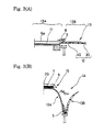
- the green tyre 1A is formed such that a tyre covering rubber 12 comprising the inner liner rubber 11, a chafer rubber 4G and sidewall rubber 3G are assemble together on a building drum and the carcass ply 6a and the like are sequentially wound to form a cylindrical base 13 and then, bead cores 5 on which bead apex rubbers 8 are mounted are set to opposite sides of the cylindrical base 13.
- a main portion 13A of building drum cylindrical base 13 between the bead cores 5 and 5 is expanded to bring the main portion 13A into contact under pressure with an inner peripheral surface of an annular tread ring 15 including a pre-assembled belt layer 7, a band layer 9 and a tread rubber 2G, and the side portions 13B outside the bead core 5 are folded up to contact the main portion 13A, thereby forming the green tyre 1A in its spread form.
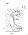
- the vulcanising mould 20 comprises a mould body 21 having a tyre forming surface 23, and a bladder 22 for pressing the tyre inner surface of a green tyre 1A mounted in the tyre forming surface 23.
- the vulcanising mould body 21 comprises an upper mould 21U for forming one of the tyre outside surfaces, a lower mould 21L for forming the other tyre outside surface, and a plurality of segments 21T capable of forming the tread surface.
- the upper mould 21U and the segments 21T By mounting the upper mould 21U and the segments 21T to a ram of a press, and by mounting the lower mould 21L to a bed, the upper mould 21U, the lower mould 21L and the segments 21T can be united together or separated from one another by the vertical movement of the ram.
- a forming chamber surrounded by the tyre forming surface 23 is formed.
- the bladder 22 is a bag-like resilient sheet body formed using rubber, synthetic resin or the like. By charging high temperature and high pressure gas or liquid into the bladder 22, the bladder 22 is expanded, and this presses the green tyre 1A against the tyre forming surface 23. Thus the vulcanising process and the forming process are carried out simultaneously.
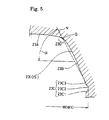
- the tyre forming surface 23 comprises a tread forming surface portion 23A forming an outer surface of the tread portion 2, a sidewall forming surface portion 23B forming an outer surface of the sidewall portion 3, and a bead forming surface portion 23C forming an outer surface of the bead portion 4.
- the bead forming surface portion 23C comprises a bottom surface corresponding portion 23C1 forming the bead bottom surface portion S1, a bead heel corresponding portion 23C2 forming the bead heel S2, and a flange contact surface corresponding portion 23C3 forming the flange contact surface portion S3.
- the tyre forming surface 23 has substantially the same outline as that of the unvulcanised green tyre outer surface OS. Therefore, the tyre forming surface 23 has a substantially spreading shape in the radially inward direction over a region from the tread forming surface portion 23A to the bead heel corresponding portion 23C2 through the sidewall forming surface portion 23B, and a width W of the tyre forming surface 23 between the bead heel corresponding portions 23C2 and 23C2 is the maximum width W1.
- the angle ⁇ defined between a tyre axial direction line and a line segment N extending from the bead heel corresponding portion 23C2 through a position Q is set to 85 degrees or smaller.
- the position Q is the position of intermediate height of a curved surface of a minimum diameter portion 23D between the tread forming surface portion 23A and the sidewall forming surface portion 23B.
- This angle ⁇ is an index of the spreading degree, and by setting this angle at 85 degrees or smaller to increase the spreading degree, the outward projection from the maximum width position P of the bead portion 4 can be set greater and more reliably, and it is then possible to further improve the suppressing effect of the disturbance of the cord arrangement. If the angle ⁇ is greater than 85 degrees, the suppressing effect might be insufficient.
- the tyre inner surface IS in the substantially spreading shape, as shown in Fig. 6, it is possible to prevent the bladder 22 from needing on over-hang portion 30 in the tyre axially outward direction for expanding, unlike the conventional tyre.
- trapped air 16 is prone to be held in a position of the over-hang portion 30 between the green tyre 1A and the bladder 22, and there is a tendency that the tyre shaping precision is lowered and uniformity is deteriorated. Therefore, by forming the pneumatic tyre 1 into the above-mentioned outline, the uniformity can further be enhanced.
- the present application is not be limited to a tyre for a passenger car, and can be applied to tyres for various purposes such as a heavy load tyres and small truck tyre, and a bias structure other than the radial structure can also be employed as the carcass.
- tyres for a passenger car having a tyre size of 195/65R16 were made based on the specifications shown in Table 1, and the noise and steering stability of the tyres were measured.
- the tyres were produced by vulcanising and forming substantially the same green tyres, and only the outline shapes at the time of the vulcanisation were different and other specifications were all the same.
- the sample tyres were mounted on all the wheels of a passenger car (2000 cc) each on a rim (6JJ ⁇ 16) and at standard internal pressure (200 kpa).
- the passenger car was run on a hot rolled road (asphalt road surface) and on a bitumen road (road surface on which chesils are spread) at a speed of 60 km an hour, and the over all (O.A.) and the noise level (dB(A)) at 160Hz were measured by a microphone set at the side of a right ear portion of a driving seat. On the hot rolled road, the noise level at 250 Hz was also measured.
- the above-mentioned car was run on a tyre test course, and the steering wheel response performance, turning performance, wet grip performance and riding comfort degree were evaluated each on a scale of 10 by the driver's sensory evaluation. The result is better as the score is higher.
- the weight of the sample tyre, the vertical spring coefficient, the lateral spring coefficient, the cornering power (CP), the cornering force (CF), the self aligning torque power (SATP), the rolling resistance coefficient (RRC), the projection climbing over performance, and resonance frequency of the tyre were measured by laboratory test, and the results are shown in Table 1.
- the RRC is a value obtained by dividing the rolling resistance value by a load at that time. @1° and @12° in CP, CF and SATP show slip angle.
- the resonance frequency of the tyre was calculated such that a tread centre of a tyre having a rim (6JJ ⁇ 16) and internal pressure (200 kpa) therein was vibrated by an impact hammer (input of about 20 kgf), its output is detected by, e.g., a piezoelectric triaxial load cell, and the correlation between these input and output is analysed by a computer, thereby calculating resonance frequency in the circumferential direction and the radial direction which are inherent in a tyre.
- the cord distribution of the tyre of the embodiment was smaller than that of the conventional product and that wave of the carcass cord is suppressed and the uniformity is improved. Further, it was confirmed that the tyre of the embodiment was excellent in respect of tyre noise and steering stability, especially the steering wheel response performance on a dry road surface.
Landscapes
- Engineering & Computer Science (AREA)
- Mechanical Engineering (AREA)
- Moulds For Moulding Plastics Or The Like (AREA)
- Tires In General (AREA)
- Heating, Cooling, Or Curing Plastics Or The Like In General (AREA)
- Tyre Moulding (AREA)
- Air Bags (AREA)
Applications Claiming Priority (2)
| Application Number | Priority Date | Filing Date | Title |
|---|---|---|---|
| JP18230198 | 1998-06-29 | ||
| JP10182301A JP3133982B2 (ja) | 1998-06-29 | 1998-06-29 | 空気入りタイヤ、及びその製造方法 |
Publications (4)
| Publication Number | Publication Date |
|---|---|
| EP0968846A2 true EP0968846A2 (de) | 2000-01-05 |
| EP0968846A3 EP0968846A3 (de) | 2001-05-02 |
| EP0968846B1 EP0968846B1 (de) | 2005-10-19 |
| EP0968846B9 EP0968846B9 (de) | 2006-01-18 |
Family
ID=16115905
Family Applications (1)
| Application Number | Title | Priority Date | Filing Date |
|---|---|---|---|
| EP19990305000 Expired - Lifetime EP0968846B9 (de) | 1998-06-29 | 1999-06-25 | Luftreifen, Verfahren zu seiner Herstellung und Vulkanisierform für ein Luftreifen Herstellungsverfahren |
Country Status (3)
| Country | Link |
|---|---|
| EP (1) | EP0968846B9 (de) |
| JP (1) | JP3133982B2 (de) |
| DE (1) | DE69927749T2 (de) |
Cited By (2)
| Publication number | Priority date | Publication date | Assignee | Title |
|---|---|---|---|---|
| US6827115B1 (en) | 1999-10-18 | 2004-12-07 | John See Van Hoose | Bead construction |
| US6964719B1 (en) | 1999-10-18 | 2005-11-15 | The Goodyear Tire & Rubber Company | Process for manufacturing tires |
Families Citing this family (7)
| Publication number | Priority date | Publication date | Assignee | Title |
|---|---|---|---|---|
| JP5091599B2 (ja) * | 2007-09-14 | 2012-12-05 | 住友ゴム工業株式会社 | 空気入りタイヤ及びその製造方法 |
| JP5262605B2 (ja) * | 2008-11-14 | 2013-08-14 | 横浜ゴム株式会社 | 空気入りタイヤの製造方法 |
| JP2019001099A (ja) * | 2017-06-16 | 2019-01-10 | 住友ゴム工業株式会社 | 空気入りタイヤの製造方法、タイヤ加硫金型、及び、空気入りタイヤ |
| JP6950370B2 (ja) * | 2017-08-30 | 2021-10-13 | 住友ゴム工業株式会社 | 空気入りラジアルタイヤ |
| JP6950368B2 (ja) * | 2017-08-30 | 2021-10-13 | 住友ゴム工業株式会社 | 空気入りラジアルタイヤ |
| JP6950371B2 (ja) * | 2017-08-30 | 2021-10-13 | 住友ゴム工業株式会社 | 空気入りラジアルタイヤ |
| JP6950369B2 (ja) * | 2017-08-30 | 2021-10-13 | 住友ゴム工業株式会社 | 空気入りラジアルタイヤ |
Family Cites Families (2)
| Publication number | Priority date | Publication date | Assignee | Title |
|---|---|---|---|---|
| US4513802A (en) * | 1982-03-16 | 1985-04-30 | Bridgestone Tire Company Limited | Reduced rolling resistance pneumatic radial tire and method of manufacturing the same |
| JPH07228104A (ja) * | 1993-12-24 | 1995-08-29 | Toyo Tire & Rubber Co Ltd | 空気入りタイヤおよびその製造方法 |
-
1998
- 1998-06-29 JP JP10182301A patent/JP3133982B2/ja not_active Expired - Fee Related
-
1999
- 1999-06-25 DE DE69927749T patent/DE69927749T2/de not_active Expired - Fee Related
- 1999-06-25 EP EP19990305000 patent/EP0968846B9/de not_active Expired - Lifetime
Cited By (2)
| Publication number | Priority date | Publication date | Assignee | Title |
|---|---|---|---|---|
| US6827115B1 (en) | 1999-10-18 | 2004-12-07 | John See Van Hoose | Bead construction |
| US6964719B1 (en) | 1999-10-18 | 2005-11-15 | The Goodyear Tire & Rubber Company | Process for manufacturing tires |
Also Published As
| Publication number | Publication date |
|---|---|
| JP2000016011A (ja) | 2000-01-18 |
| DE69927749D1 (de) | 2006-03-02 |
| EP0968846A3 (de) | 2001-05-02 |
| EP0968846B9 (de) | 2006-01-18 |
| JP3133982B2 (ja) | 2001-02-13 |
| DE69927749T2 (de) | 2006-07-06 |
| EP0968846B1 (de) | 2005-10-19 |
Similar Documents
| Publication | Publication Date | Title |
|---|---|---|
| EP1430277B1 (de) | Verfahren zur bestimmung von parametern eines sitzpassagiers | |
| US7036541B2 (en) | Pneumatic tire | |
| US5117886A (en) | Pneumatic radial tire for passenger cars | |
| JP3527699B2 (ja) | 空気入りタイヤ | |
| JP2887172B2 (ja) | 空気入りタイヤ | |
| EP0890454B1 (de) | Verbesserungen in Reifen | |
| EP0968846B9 (de) | Luftreifen, Verfahren zu seiner Herstellung und Vulkanisierform für ein Luftreifen Herstellungsverfahren | |
| JP4237638B2 (ja) | 空気入りタイヤ | |
| JP2002002216A (ja) | 空気入りタイヤ | |
| US5411069A (en) | Pneumatic radial tires including an annular recess portion in the tread | |
| JPH0761214A (ja) | 燃費にすぐれる空気入りラジアルタイヤ | |
| JP4537517B2 (ja) | 空気入りラジアルタイヤの製造方法 | |
| US5238039A (en) | Pneumatic radial tires having carcass line with plural inflection points | |
| JP2002518231A5 (de) | ||
| JP2003094912A (ja) | ランフラットタイヤ及びその製造方法 | |
| JPH0958212A (ja) | 空気入りタイヤ | |
| JP2004237808A (ja) | 空気入りタイヤ及びその製造方法 | |
| JP2002127713A (ja) | 空気入りタイヤ | |
| EP0317318B1 (de) | Verfahren zur Herstellung von Reifen | |
| JP2003191713A (ja) | 空気入りラジアルタイヤ | |
| JP3410648B2 (ja) | 重荷重用タイヤ及びその製造方法 | |
| JP2978472B1 (ja) | 空気入りタイヤ | |
| JP2002120515A (ja) | 空気入りタイヤ | |
| JP2005239068A (ja) | 空気入りタイヤ | |
| JPH11321216A (ja) | 重荷重用タイヤ |
Legal Events
| Date | Code | Title | Description |
|---|---|---|---|
| PUAI | Public reference made under article 153(3) epc to a published international application that has entered the european phase |
Free format text: ORIGINAL CODE: 0009012 |
|
| AK | Designated contracting states |
Kind code of ref document: A2 Designated state(s): DE FR GB |
|
| AX | Request for extension of the european patent |
Free format text: AL;LT;LV;MK;RO;SI |
|
| RIC1 | Information provided on ipc code assigned before grant |
Free format text: 7B 60C 3/04 A, 7B 29D 30/20 B |
|
| PUAL | Search report despatched |
Free format text: ORIGINAL CODE: 0009013 |
|
| AK | Designated contracting states |
Kind code of ref document: A3 Designated state(s): AT BE CH CY DE DK ES FI FR GB GR IE IT LI LU MC NL PT SE |
|
| AX | Request for extension of the european patent |
Free format text: AL;LT;LV;MK;RO;SI |
|
| 17P | Request for examination filed |
Effective date: 20010710 |
|
| AKX | Designation fees paid |
Free format text: DE FR GB |
|
| 17Q | First examination report despatched |
Effective date: 20040427 |
|
| GRAP | Despatch of communication of intention to grant a patent |
Free format text: ORIGINAL CODE: EPIDOSNIGR1 |
|
| GRAS | Grant fee paid |
Free format text: ORIGINAL CODE: EPIDOSNIGR3 |
|
| GRAA | (expected) grant |
Free format text: ORIGINAL CODE: 0009210 |
|
| AK | Designated contracting states |
Kind code of ref document: B1 Designated state(s): DE FR GB |
|
| REG | Reference to a national code |
Ref country code: GB Ref legal event code: FG4D |
|
| REF | Corresponds to: |
Ref document number: 69927749 Country of ref document: DE Date of ref document: 20060302 Kind code of ref document: P |
|
| ET | Fr: translation filed | ||
| PGFP | Annual fee paid to national office [announced via postgrant information from national office to epo] |
Ref country code: GB Payment date: 20060615 Year of fee payment: 8 |
|
| PLBE | No opposition filed within time limit |
Free format text: ORIGINAL CODE: 0009261 |
|
| STAA | Information on the status of an ep patent application or granted ep patent |
Free format text: STATUS: NO OPPOSITION FILED WITHIN TIME LIMIT |
|
| 26N | No opposition filed |
Effective date: 20060720 |
|
| GBPC | Gb: european patent ceased through non-payment of renewal fee |
Effective date: 20070625 |
|
| PG25 | Lapsed in a contracting state [announced via postgrant information from national office to epo] |
Ref country code: GB Free format text: LAPSE BECAUSE OF NON-PAYMENT OF DUE FEES Effective date: 20070625 |
|
| PGFP | Annual fee paid to national office [announced via postgrant information from national office to epo] |
Ref country code: DE Payment date: 20090619 Year of fee payment: 11 |
|
| REG | Reference to a national code |
Ref country code: FR Ref legal event code: ST Effective date: 20110228 |
|
| PG25 | Lapsed in a contracting state [announced via postgrant information from national office to epo] |
Ref country code: DE Free format text: LAPSE BECAUSE OF NON-PAYMENT OF DUE FEES Effective date: 20110101 |
|
| PG25 | Lapsed in a contracting state [announced via postgrant information from national office to epo] |
Ref country code: FR Free format text: LAPSE BECAUSE OF NON-PAYMENT OF DUE FEES Effective date: 20100630 |
|
| PGFP | Annual fee paid to national office [announced via postgrant information from national office to epo] |
Ref country code: FR Payment date: 20090611 Year of fee payment: 11 |