EP0968885B1 - Refroidissement d'une unité de commande moteur - Google Patents
Refroidissement d'une unité de commande moteur Download PDFInfo
- Publication number
- EP0968885B1 EP0968885B1 EP99201875A EP99201875A EP0968885B1 EP 0968885 B1 EP0968885 B1 EP 0968885B1 EP 99201875 A EP99201875 A EP 99201875A EP 99201875 A EP99201875 A EP 99201875A EP 0968885 B1 EP0968885 B1 EP 0968885B1
- Authority
- EP
- European Patent Office
- Prior art keywords
- ecu
- plate
- control unit
- fuel
- chill plate
- Prior art date
- Legal status (The legal status is an assumption and is not a legal conclusion. Google has not performed a legal analysis and makes no representation as to the accuracy of the status listed.)
- Expired - Lifetime
Links
- 238000001816 cooling Methods 0.000 title claims description 14
- 239000000446 fuel Substances 0.000 claims description 31
- 238000005058 metal casting Methods 0.000 claims description 5
- 238000005192 partition Methods 0.000 claims description 5
- 238000007789 sealing Methods 0.000 claims description 4
- 230000035939 shock Effects 0.000 claims description 4
- 241001247986 Calotropis procera Species 0.000 claims description 3
- 239000000110 cooling liquid Substances 0.000 claims description 2
- 230000013011 mating Effects 0.000 claims description 2
- 238000005266 casting Methods 0.000 description 4
- 239000012530 fluid Substances 0.000 description 3
- 239000004411 aluminium Substances 0.000 description 2
- 229910052782 aluminium Inorganic materials 0.000 description 2
- XAGFODPZIPBFFR-UHFFFAOYSA-N aluminium Chemical compound [Al] XAGFODPZIPBFFR-UHFFFAOYSA-N 0.000 description 2
- 239000000919 ceramic Substances 0.000 description 2
- 239000004020 conductor Substances 0.000 description 2
- 239000002826 coolant Substances 0.000 description 2
- 239000012809 cooling fluid Substances 0.000 description 2
- 239000000498 cooling water Substances 0.000 description 2
- 229910052751 metal Inorganic materials 0.000 description 2
- 239000002184 metal Substances 0.000 description 2
- 230000005540 biological transmission Effects 0.000 description 1
- 238000010276 construction Methods 0.000 description 1
- 239000000284 extract Substances 0.000 description 1
- 239000002828 fuel tank Substances 0.000 description 1
- 238000002347 injection Methods 0.000 description 1
- 239000007924 injection Substances 0.000 description 1
- 238000002955 isolation Methods 0.000 description 1
- 239000007788 liquid Substances 0.000 description 1
- 230000007257 malfunction Effects 0.000 description 1
- 238000000034 method Methods 0.000 description 1
- 230000002093 peripheral effect Effects 0.000 description 1
- XLYOFNOQVPJJNP-UHFFFAOYSA-N water Substances O XLYOFNOQVPJJNP-UHFFFAOYSA-N 0.000 description 1
Images



Classifications
-
- B—PERFORMING OPERATIONS; TRANSPORTING
- B60—VEHICLES IN GENERAL
- B60R—VEHICLES, VEHICLE FITTINGS, OR VEHICLE PARTS, NOT OTHERWISE PROVIDED FOR
- B60R16/00—Electric or fluid circuits specially adapted for vehicles and not otherwise provided for; Arrangement of elements of electric or fluid circuits specially adapted for vehicles and not otherwise provided for
- B60R16/02—Electric or fluid circuits specially adapted for vehicles and not otherwise provided for; Arrangement of elements of electric or fluid circuits specially adapted for vehicles and not otherwise provided for electric constitutive elements
- B60R16/023—Electric or fluid circuits specially adapted for vehicles and not otherwise provided for; Arrangement of elements of electric or fluid circuits specially adapted for vehicles and not otherwise provided for electric constitutive elements for transmission of signals between vehicle parts or subsystems
- B60R16/0239—Electronic boxes
-
- F—MECHANICAL ENGINEERING; LIGHTING; HEATING; WEAPONS; BLASTING
- F28—HEAT EXCHANGE IN GENERAL
- F28F—DETAILS OF HEAT-EXCHANGE AND HEAT-TRANSFER APPARATUS, OF GENERAL APPLICATION
- F28F3/00—Plate-like or laminated elements; Assemblies of plate-like or laminated elements
- F28F3/12—Elements constructed in the shape of a hollow panel, e.g. with channels
-
- H—ELECTRICITY
- H05—ELECTRIC TECHNIQUES NOT OTHERWISE PROVIDED FOR
- H05K—PRINTED CIRCUITS; CASINGS OR CONSTRUCTIONAL DETAILS OF ELECTRIC APPARATUS; MANUFACTURE OF ASSEMBLAGES OF ELECTRICAL COMPONENTS
- H05K7/00—Constructional details common to different types of electric apparatus
- H05K7/20—Modifications to facilitate cooling, ventilating, or heating
- H05K7/20845—Modifications to facilitate cooling, ventilating, or heating for automotive electronic casings
- H05K7/20872—Liquid coolant without phase change
Definitions
- the present invention relates to the cooling of an electronic control unit (ECU) of an engine, in particular a diesel engine.
- ECU electronice control unit
- the chill plate comprises a coolant chamber which, in use, is connected in a supply line through which passes fuel flowing from a fuel reservoir to the engine.
- the chill plate serves to cool the ECU module by transferring heat to the fuel supplied to the engine.
- the known chill plates have the disadvantage that they can only be used with ECU's having a flat heat sink of conductive material to which the heat generating electronic components are attached.
- an engine electronic control unit (ECU) and chill plate assembly is described with a housing comprising: a base on one side of which the components of the ECU are mounted either directly or indirectly (i.e. via a ceramic board), the base being formed with a central pocket for accommodating any components protruding from the rear face of the ECU ceramic board, a recess being formed in the opposite side of the base to the ECU components; an upper enclosure fixed to the base and covering the components; and a closure fixed to to the side of the base to cooperate with the recess to define a cooling water passage, the cooling water passage extending around at least part of the periphery of the central pocket and an area covering the full region of the central pocket to transfer heat to the water from the pocket and a region of the base adjacent the pocket.
- the chill plate and ECU assembly comprises a cooling fluid passage which covers the full region of the ECU, thus cooling all components of the ECU, irrespective of the amount of heat the individual components produce.
- the cooling passage moreover is merely an open space with an inlet and an outlet resulting in an inefficient use of the cooling capacity of the cooling fluid since the fluid is not forced around the ECU components in a predetermined path.
- a chill plate for cooling an electronic control unit of an engine comprising a housing having a flat front face onto which the ECU may be mounted, the housing being formed with a central pocket for accommodating any components protruding from the rear face of the ECU; the chill plate further comprising a passage within the housing through which cooling liquid may flow, wherein the ECU has a rear backing plate comprising a substantially circumferentially provided surface mating with said flat front face of the chill plate and which needs to be cooled, and a box that protrudes from said surface; said passage comprising flow conduits through which fuel flows substantially only around at least part of the periphery of the central pocket to transfer heat to the fuel from the regions of the front face surrounding the pocket.
- the housing is preferably formed with mounting bosses for receiving shock and vibration absorbing rubber bushes.
- the housing may conveniently be formed of a metal casting defining an open channel surrounding three sides of the central pocket, and a cover plate for closing the open channel to constitute the fuel flow conduits.
- the cover plate is preferably welded to the metal casting.
- the open channel may comprise one or more partitions such that the fuel in the flow conduits is constrained to follow a convoluted path.
- an ECU has a metal backing plate with the result that when the ECU is fitted to the chill plate there will be two layers of metal between the liquid coolant and the circuit components to be cooled.
- an electronic control unit for an engine having a rear face and a central box which accommodates components protruding from the rear face of the ECU, and wherein a plate comprising a raised outer wall portion extending around the periphery of the plate is mounted on the ECU in sealing engagement with the rim of the rear face to define in combination with the rear face and the box a chamber for circulation of fuel for cooling the ECU, the chamber comprising a flow conduit through which fuel flows substantially only around at least part of the periphery of the box to transfer heat to the fuel from regions of the rear face of the ECU surrounding the box.
- FIG 3 shows a prior art type of ECU 10 that is currently available and in use in engine management systems.
- This ECU 10 presents no particular problem as it has a flat rear face 12 that needs to be cooled around its periphery.
- Such an ECU can be cooled using a flat chill plate, as already known in the prior art.
- FIGS 4 and 5 show a different type of ECU 20 that is also currently in use and differs from that of Figure 3.
- the ECU 20 On its front face, the ECU 20 has various electrical connection terminals 22, 24.
- the ECU 20 On its rear face, the ECU 20 has a surface 26 that needs to be cooled and a box 28 that protrudes from that surface.
- the parts of the rear surface 26 that need to be cooled are located partly circumferentially around the box 28 and it will be clear that such an ECU cannot be cooled using a flat chill plate as the protruding box 28 would prevent the parts of the rear surface 26 that need to be cooled from contacting the chill plate.
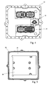
- the invention provides a chill plate 30 that is shown in Figures 1 and 2.
- the chill plate 30 is formed of two parts that are welded to each other, namely an aluminium casting 32 and a cover plate 34.
- the casting defines a pocket 36 recessed into the flat front face 38 of the chill plate, which pocket is surrounded on three sides by a channel 40 of U-shaped cross section.
- flow conduits are formed for fuel that enters the chill plate 30 through a fuel inlet 46 and leaves through a fuel outlet 48.
- Two partition walls 42, 44 are cast into the upper and lower sides of the channel 40, respectively, to constrain the fuel to follow a convoluted flow path through the flow conduit to increase residence time and the effective heat transfer from the electronic components.
- the ECU 20 of Figures 3 and 4 can be mounted on the chill plate because its protruding box 28 can be accommodated in the pocket 36.
- the chill plate is connected in series in the pipe leading from the fuel tank to the fuel injection system of the engine.
- the fuel follows the path shown by the arrow 50 in Figure 7.
- the fuel enters from the inlet 46, traverses the upper side of the channel 40 twice, descends along the vertical side and traverses the lower side of the channel 40 twice before leaving through the outlet 48.
- the fuel extracts heat from the periphery of the front surface 38 of the chill plate 30 which is in thermal contact with the surface 26 of the ECU 20 that needs to be cooled.
- the chill plate 30 is intended for mounting directly on the engine.
- the chill plate has three engine mounting bosses 52 that are designed to receive rubber bushes 54 ( Figure 6) which are positioned between the bosses 52 and mounting screws which attach to the engine receiving the ECU 20. These bushes absorb shocks and vibrations and also provide thermal isolation between the chill plate 30 and the engine mounts.
- chill plate 30 can equally well accept an ECU of the type shown in Figure 3 that has no protrusions that inhibit the surface to be cooled from being brought into thermal contact with the cooling surface of the chill plate 30.
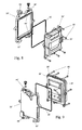
- the ECU 20' of Figures 8 and 9 has electrical connectors 22' on its front face and a box 28' containing electrical components projecting from its rear face 26'.
- a plate 30' formed as a casting of aluminium or other heat conductive material is mounted by means of screws 60 directly onto the rear face 26' of the ECU 20' and is sealed against it by means of a resilient gasket or rubber ring 62 received in a continuous perimeter groove in the plate 30'.
- the plate 30' When the plate 30' is assembled to the ECU 20', it defines a sealed cooling chamber having a central pocket constituted by the box 28'.
- the region of the chamber surrounding the box 28' is divided by a partition wall 44' formed as part of the casting of the plate 30' into a convoluted flow path like the path shown in Figure 2 that surrounds and cools the periphery of the central pocket. Fuel enters and leaves the flow path through connectors 46' and 48'.
- the seal 62 prevents fuel from leaking out of the cooling chamber but it is not necessary to take any steps to prevent fuel from reaching the space between the central box 28' and the plate 30'. As the maximum depth of the box 28' is selected to closely fit the facing side of the plate 30', there will be only a small leakage from the convoluted fuel flow path which will not detract significantly from the cooling of the peripheral regions of the ECU 20'.
- the plate 30' can once again be used to mount the ECU 20' to an engine and to this end it is provided with bosses 52' for receiving shock absorbing mounting bushes.
Landscapes
- Engineering & Computer Science (AREA)
- Physics & Mathematics (AREA)
- Thermal Sciences (AREA)
- Mechanical Engineering (AREA)
- Microelectronics & Electronic Packaging (AREA)
- General Engineering & Computer Science (AREA)
- Fuel-Injection Apparatus (AREA)
- Cooling Or The Like Of Electrical Apparatus (AREA)
- Cooling, Air Intake And Gas Exhaust, And Fuel Tank Arrangements In Propulsion Units (AREA)
- Cylinder Crankcases Of Internal Combustion Engines (AREA)
Claims (10)
- Refroidisseur (30) pour le refroidissement de l'unité de commande électronique (UCE) d'un moteur, comprenant un carter (32, 34) possédant un devant plat (38) sur lequel l'UCE (20, 20') peut être montée, le carter étant constitué d'une poche centrale (36) pour accueillir les composants (28) qui dépassent de la face arrière (26) de l'UCE, le refroidisseur (30) comprenant en outre un passage (40) dans le carter à travers lequel le liquide de refroidissement peut s'écouler, et dans lequel
l'UCE (20) possède une plaque de renforcement arrière comprenant une surface (26) prévue de manière essentiellement circonférentielle, s'adaptant avec ledit devant plat (38) du refroidisseur et qui doit être refroidie, et un boîtier (28) qui dépasse de ladite surface (26) ; ledit passage (40) comprenant des conduits d'écoulement (40) à travers lesquels le carburant s'écoule uniquement pour l'essentiel autour d'au moins une partie de la périphérie de la poche centrale (36 de manière à transférer la chaleur du carburant depuis les régions du devant (38) entourant la poche (36). - Unité de commande électronique (UCE) avec un refroidisseur selon la revendication 1, caractérisée en ce que le carter du refroidisseur (32, 34) est formé avec des pastilles de montage (52) pour recevoir des douilles en caoutchouc absorbant les chocs et les vibrations (54), de manière à permettre le montage direct du refroidisseur (30) sur un moteur.
- Unité de commande électronique (UCE) avec un refroidisseur selon la revendication 1 ou 2, caractérisée en ce que le carter du refroidisseur (32, 34) est formé d'une pièce moulée en métal définissant un profilé ouvert (40) entourant trois côtés de la poche centrale (36) et d'un couvercle (34) pour refermer le profilé ouvert (40) de manière à constituer les conduits d'écoulement du carburant.
- Unité de commande électronique (UCE) avec un refroidisseur selon la revendication 3, caractérisée en ce que le couvercle (34) est soudé à la pièce moulée en métal.
- Unité de commande électronique (UCE) avec un refroidisseur selon la revendication 3 ou 4, caractérisée en ce que le profilé ouvert (40) comprend une ou plusieurs séparations (42, 44) de manière telle que le carburant présent dans les conduits d'écoulement soit contraint de suivre un trajet contourné.
- Unité de commande électronique (UCE) (20') pour un moteur possédant une face arrière (26') et un boîtier central (28') qui accueille les composants dépassant de la surface arrière (26') de l'UCE (20'), dans laquelle
une plaque (30') comprenant une partie de paroi extérieure relevée s'étendant sur la périphérie de la plaque (30') est montée sur l'UCE (20') en engagement de fermeture avec le bord de la face arrière (26') de manière à définir, en combinaison avec la face arrière (26') et le boîtier (28'), une chambre pour la circulation du carburant en vue du refroidissement de l'UCE (20'), ladite chambre comprenant un conduit d'écoulement à travers lequel du carburant s'écoule essentiellement autour d'une partie au moins seulement de la périphérie de la boîte (28') de manière à transférer la chaleur du carburant depuis les zones de la face arrière (26') de l'UCE (20') entourant le boîtier (28'). - Unité de commande électronique selon la revendication 6, caractérisée en ce que la tôle (30') a la forme d'une pièce moulée en métal avec au moins un cloison de séparation relevée (44') qui divise les régions de la chambre entourant le boîtier central (28') dans un conduit d'écoulement contoumé.
- Unité de commande électronique selon la revendication 6 ou 7, caractérisée en ce qu'un fond du boîtier central (28') s'étend de manière étroitement adjacente à la tôle (30') pour obliger le carburant à s'écouler selon un trajet autour d'au moins une partie de la périphérie dudit boîtier central (28').
- Unité de commande électronique selon les revendication 6 à 8, caractérisée en ce qu'un élément de fermeture continu (62) s'étend autour de la périphérie du boîtier central (28') pour enfermer le carburant dans ladite chambre.
- Unité de commande électronique selon l'une quelconque des revendication 6 à 9, caractérisée en ce que l'UCE (20') est fixée de manière amovible à la tôle (30') au moyen d'une pluralité de vis (60).
Applications Claiming Priority (2)
| Application Number | Priority Date | Filing Date | Title |
|---|---|---|---|
| GB9814082 | 1998-06-30 | ||
| GB9814082A GB2339081A (en) | 1998-06-30 | 1998-06-30 | Cooling an engine control unit using fuel as coolant |
Publications (3)
| Publication Number | Publication Date |
|---|---|
| EP0968885A2 EP0968885A2 (fr) | 2000-01-05 |
| EP0968885A3 EP0968885A3 (fr) | 2003-10-29 |
| EP0968885B1 true EP0968885B1 (fr) | 2006-06-14 |
Family
ID=10834628
Family Applications (1)
| Application Number | Title | Priority Date | Filing Date |
|---|---|---|---|
| EP99201875A Expired - Lifetime EP0968885B1 (fr) | 1998-06-30 | 1999-06-14 | Refroidissement d'une unité de commande moteur |
Country Status (5)
| Country | Link |
|---|---|
| US (1) | US6302190B1 (fr) |
| EP (1) | EP0968885B1 (fr) |
| JP (1) | JP2000034942A (fr) |
| DE (1) | DE69931848T2 (fr) |
| GB (1) | GB2339081A (fr) |
Families Citing this family (33)
| Publication number | Priority date | Publication date | Assignee | Title |
|---|---|---|---|---|
| FR2809281B1 (fr) * | 2000-05-22 | 2002-07-12 | Alstom | Dispositif electronique de puissance |
| EP1319818B1 (fr) * | 2000-09-22 | 2008-09-10 | Aisin Aw Co., Ltd. | Dispositif d'entrainement a circuit electronique |
| DE20115922U1 (de) * | 2001-01-11 | 2002-01-17 | Siemens AG, 80333 München | Kunststoff-Schaltplatte eines hydraulischen Kraftfahrzeug-Getriebesteuergerätes |
| DE10101091A1 (de) * | 2001-01-11 | 2002-07-25 | Siemens Ag | Hydraulisches Kraftfahrzeug-Getriebesteuergerät mit Kunststoff-Hydraulikverteilerplatte und darin integrierten Leitern und Verfahren zu dessen Herstellung |
| JP2002368466A (ja) * | 2001-06-06 | 2002-12-20 | Yazaki Corp | 電子制御ユニットの冷却構造 |
| US6669505B2 (en) | 2001-09-13 | 2003-12-30 | Siemens Vdo Automotive Corporation | Vehicle electronic control units |
| US6860242B2 (en) * | 2002-07-01 | 2005-03-01 | Cummins, Inc. | Lift pump mounting bracket for an electronic control module cooler |
| GB0306917D0 (en) * | 2003-03-26 | 2003-04-30 | Trw Ltd | A vehicle electronic control unit |
| DE10317705A1 (de) | 2003-04-17 | 2004-10-28 | Robert Bosch Gmbh | Gehäuse mit Kühlung für elektronische Steuergeräte, insbesondere in Kfz |
| WO2006108392A1 (fr) * | 2005-04-15 | 2006-10-19 | Conti Temic Microelectronic Gmbh | Appareil de commande |
| DE102005032814A1 (de) * | 2005-07-12 | 2007-01-18 | Behr Gmbh & Co. Kg | Kühlvorrichtung, insbesondere für ein elektronisches Steuergerät |
| DE102005036299B4 (de) * | 2005-08-02 | 2008-01-24 | Siemens Ag | Kühlanordnung |
| US20080053412A1 (en) * | 2006-08-29 | 2008-03-06 | Aisan Kogyo Kabushiki Kaisha | Fuel supply systems |
| GB0622516D0 (en) * | 2006-11-11 | 2006-12-20 | Rolls Royce Plc | Cooling arrangement for electronics |
| US9743563B2 (en) * | 2007-03-20 | 2017-08-22 | Conti Temic Microelectronic Gmbh | Control appliance for using in the engine compartment or in the transmission of a motor vehicle and cooling system for such a control appliance |
| DE102007054246A1 (de) * | 2007-11-14 | 2009-05-20 | Daimler Ag | Brennstoffzellenantrieb für ein Kraftfahrzeug |
| JP5184286B2 (ja) * | 2008-09-30 | 2013-04-17 | 富士通テン株式会社 | 筐体固定構造 |
| EP2179895B1 (fr) * | 2008-10-24 | 2011-09-28 | Harman Becker Automotive Systems GmbH | Système électronique de véhicule avec refroidissement de fluide |
| JP5378864B2 (ja) * | 2009-04-03 | 2013-12-25 | 富士通テン株式会社 | 車載用電子機器の筐体構造 |
| US9596785B2 (en) * | 2010-03-22 | 2017-03-14 | Pratt & Whitney Canada Corp. | Heat exchanger |
| DE102010063155A1 (de) * | 2010-12-15 | 2012-06-21 | Robert Bosch Gmbh | Befestigungsvorrichtung für ein Gehäuse eines Steuergerätes |
| DE102011008355A1 (de) * | 2011-01-12 | 2012-07-12 | Volkswagen Ag | Vorrichtung, Gehäuse, Anordnung und Verfahren zur Kühlung mindestens eines elektrischen oder elektronischen Elements |
| CN202077285U (zh) * | 2011-04-29 | 2011-12-14 | 博世汽车部件(苏州)有限公司 | 安全气囊控制器外壳 |
| US9217355B2 (en) * | 2011-12-12 | 2015-12-22 | Caterpillar Inc. | Sensor mounting arrangement |
| CN103867324A (zh) * | 2012-12-14 | 2014-06-18 | 安徽华菱汽车有限公司 | 发动机与电子控制单元的连接装置和发动机系统 |
| USD772943S1 (en) * | 2014-06-27 | 2016-11-29 | Denso Corporation | Automotive engine computer unit cover |
| WO2016189523A1 (fr) * | 2015-05-28 | 2016-12-01 | Daniel Cohen | Boîtier inviolable |
| CN108026823A (zh) * | 2015-07-16 | 2018-05-11 | 通用电气航空系统有限责任公司 | 用于冷却发热模块的方法及设备 |
| DE102017000699A1 (de) | 2017-01-26 | 2018-07-26 | Man Truck & Bus Ag | Vorrichtung zur Anbringung eines Steuergeräts an einen Verbrennungsmotor |
| US10954814B2 (en) * | 2018-09-26 | 2021-03-23 | Honeywell International Inc. | System with thin walled cooling plate for an electronic enclosure |
| CN114179732A (zh) * | 2020-09-15 | 2022-03-15 | 重庆科克发动机技术有限公司 | 一种发动机机载ecu的固定装置 |
| DE102024111027A1 (de) | 2024-04-19 | 2025-10-23 | Connaught Electronics Ltd. | Kühlvorrichtung zum Kühlen eines elektronischen Bauelementes eines Kraftfahrzeuges, Elektronische Baugruppe und Kraftfahrzeug |
| DE102024111951A1 (de) | 2024-04-29 | 2025-10-30 | Connaught Electronics Ltd. | Skalierbares Gehäusemodul für ein elektronisches Bauteil eines Kraftfahrzeuges, Elektronische Baugruppe für ein Kraftfahrzeug, Modulares Gehäusesystem, Modulare, elektronische Baugruppe und Kraftfahrzeug |
Family Cites Families (14)
| Publication number | Priority date | Publication date | Assignee | Title |
|---|---|---|---|---|
| US3996914A (en) * | 1975-06-13 | 1976-12-14 | Chrysler Corporation | Housing for mounting electronic circuit boards on an engine air intake structure |
| US4072188A (en) * | 1975-07-02 | 1978-02-07 | Honeywell Information Systems Inc. | Fluid cooling systems for electronic systems |
| DE2823666C2 (de) * | 1978-05-31 | 1986-09-04 | Robert Bosch Gmbh, 7000 Stuttgart | Elektronisches Steuergerät für Brennkraftmaschinen, insbesondere für Kraftfahrzeuge |
| US4559995A (en) * | 1982-04-21 | 1985-12-24 | Cummins Engine Company, Inc. | Assembly for cooling and dampening vibrations of a unit mounted therein |
| GB8326354D0 (en) * | 1983-10-01 | 1983-11-02 | Lucas Ind Plc | Fuel pumping apparatus |
| JPS6288876U (fr) * | 1985-11-22 | 1987-06-06 | ||
| JPH0765506B2 (ja) * | 1987-09-30 | 1995-07-19 | 株式会社日立製作所 | 自動車用電子制御装置 |
| JP3121848B2 (ja) * | 1991-01-28 | 2001-01-09 | 三信工業株式会社 | 電子部品ユニットの船外機用エンジンへの取付構造 |
| US5159529A (en) * | 1991-05-15 | 1992-10-27 | International Business Machines Corporation | Composite liquid cooled plate for electronic equipment |
| US5269372A (en) * | 1992-12-21 | 1993-12-14 | International Business Machines Corporation | Intersecting flow network for a cold plate cooling system |
| DE4416616C2 (de) * | 1994-05-11 | 1997-05-22 | Fichtel & Sachs Ag | Gehäuse |
| GB9416695D0 (en) * | 1994-08-18 | 1994-10-12 | Lucas Ind Plc | Cooled housing |
| JPH09126044A (ja) * | 1995-10-27 | 1997-05-13 | Denso Corp | 車両制御装置 |
| DE19645635C1 (de) * | 1996-11-06 | 1998-04-23 | Telefunken Microelectron | Steuergerät zur Ansteuerung des Elektromotors von Kraftfahrzeugen |
-
1998
- 1998-06-30 GB GB9814082A patent/GB2339081A/en not_active Withdrawn
-
1999
- 1999-06-14 DE DE69931848T patent/DE69931848T2/de not_active Expired - Lifetime
- 1999-06-14 EP EP99201875A patent/EP0968885B1/fr not_active Expired - Lifetime
- 1999-06-29 US US09/343,007 patent/US6302190B1/en not_active Expired - Lifetime
- 1999-06-30 JP JP11184969A patent/JP2000034942A/ja active Pending
Also Published As
| Publication number | Publication date |
|---|---|
| US6302190B1 (en) | 2001-10-16 |
| DE69931848D1 (de) | 2006-07-27 |
| EP0968885A2 (fr) | 2000-01-05 |
| GB9814082D0 (en) | 1998-08-26 |
| JP2000034942A (ja) | 2000-02-02 |
| EP0968885A3 (fr) | 2003-10-29 |
| DE69931848T2 (de) | 2006-10-19 |
| GB2339081A (en) | 2000-01-12 |
Similar Documents
| Publication | Publication Date | Title |
|---|---|---|
| EP0968885B1 (fr) | Refroidissement d'une unité de commande moteur | |
| CN110289751B (zh) | 电力转换装置 | |
| EP2179895B1 (fr) | Système électronique de véhicule avec refroidissement de fluide | |
| US10264705B2 (en) | Power conversion apparatus | |
| CN110662389B (zh) | 一种散热装置以及电子设备 | |
| JPS58144621A (ja) | 内燃エンジンのための液体冷却ユニツト | |
| US11971024B2 (en) | Hydraulic pressure supply unit | |
| US4331830A (en) | Housing for electrical components | |
| JP3877346B2 (ja) | モジュール式冷却システムシーリング | |
| US7143736B2 (en) | Filter box with resonator and reservoir | |
| CN110566516B (zh) | 一种可冷却电路板的汽车电子水泵 | |
| EP1124105A3 (fr) | Système de refroidissement de liquide | |
| US4559995A (en) | Assembly for cooling and dampening vibrations of a unit mounted therein | |
| CN113260237B (zh) | 一种光模块散热系统、光模块 | |
| KR20230135780A (ko) | 냉각수 매니폴드를 포함하는 냉각수 모듈 | |
| JP3535175B2 (ja) | 感熱構成部品の冷却を可能にする方法および装置 | |
| CN211909519U (zh) | 一种新型集成电机控制器 | |
| JP2003199293A (ja) | 電動機付駆動装置の冷却装置 | |
| CN216815137U (zh) | 一种换热器、动力总成及车辆 | |
| CN221010608U (zh) | 散热装置及域控制器 | |
| CN222073692U (zh) | 一种冷却结构、电机控制器及车辆 | |
| CN218906953U (zh) | 车载充电器和新能源汽车 | |
| CN220043996U (zh) | 域控制器外壳及具有其的域控制器 | |
| CN219042366U (zh) | 一种加固终端的散热装置 | |
| CN212851612U (zh) | 一种散热箱、汽车控制器及汽车 |
Legal Events
| Date | Code | Title | Description |
|---|---|---|---|
| PUAI | Public reference made under article 153(3) epc to a published international application that has entered the european phase |
Free format text: ORIGINAL CODE: 0009012 |
|
| AK | Designated contracting states |
Kind code of ref document: A2 Designated state(s): AT BE CH CY DE DK ES FI FR GB GR IE IT LI LU MC NL PT SE |
|
| AX | Request for extension of the european patent |
Free format text: AL;LT;LV;MK;RO;SI |
|
| RAP1 | Party data changed (applicant data changed or rights of an application transferred) |
Owner name: CNH U.K. LIMITED Owner name: IVECO (UK) LTD. Owner name: CUMMINS ENGINE COMPANY, LTD. |
|
| PUAL | Search report despatched |
Free format text: ORIGINAL CODE: 0009013 |
|
| AK | Designated contracting states |
Kind code of ref document: A3 Designated state(s): AT BE CH CY DE DK ES FI FR GB GR IE IT LI LU MC NL PT SE |
|
| AX | Request for extension of the european patent |
Extension state: AL LT LV MK RO SI |
|
| 17P | Request for examination filed |
Effective date: 20040422 |
|
| AKX | Designation fees paid |
Designated state(s): DE FR GB IT |
|
| 17Q | First examination report despatched |
Effective date: 20050429 |
|
| GRAP | Despatch of communication of intention to grant a patent |
Free format text: ORIGINAL CODE: EPIDOSNIGR1 |
|
| GRAS | Grant fee paid |
Free format text: ORIGINAL CODE: EPIDOSNIGR3 |
|
| GRAA | (expected) grant |
Free format text: ORIGINAL CODE: 0009210 |
|
| AK | Designated contracting states |
Kind code of ref document: B1 Designated state(s): DE FR GB IT |
|
| REG | Reference to a national code |
Ref country code: GB Ref legal event code: FG4D |
|
| REF | Corresponds to: |
Ref document number: 69931848 Country of ref document: DE Date of ref document: 20060727 Kind code of ref document: P |
|
| ET | Fr: translation filed | ||
| PLBE | No opposition filed within time limit |
Free format text: ORIGINAL CODE: 0009261 |
|
| STAA | Information on the status of an ep patent application or granted ep patent |
Free format text: STATUS: NO OPPOSITION FILED WITHIN TIME LIMIT |
|
| 26N | No opposition filed |
Effective date: 20070315 |
|
| REG | Reference to a national code |
Ref country code: FR Ref legal event code: PLFP Year of fee payment: 17 |
|
| PGFP | Annual fee paid to national office [announced via postgrant information from national office to epo] |
Ref country code: GB Payment date: 20150416 Year of fee payment: 17 Ref country code: DE Payment date: 20150416 Year of fee payment: 17 |
|
| PGFP | Annual fee paid to national office [announced via postgrant information from national office to epo] |
Ref country code: FR Payment date: 20150413 Year of fee payment: 17 Ref country code: IT Payment date: 20150611 Year of fee payment: 17 |
|
| REG | Reference to a national code |
Ref country code: DE Ref legal event code: R119 Ref document number: 69931848 Country of ref document: DE |
|
| GBPC | Gb: european patent ceased through non-payment of renewal fee |
Effective date: 20160614 |
|
| REG | Reference to a national code |
Ref country code: FR Ref legal event code: ST Effective date: 20170228 |
|
| PG25 | Lapsed in a contracting state [announced via postgrant information from national office to epo] |
Ref country code: DE Free format text: LAPSE BECAUSE OF NON-PAYMENT OF DUE FEES Effective date: 20170103 Ref country code: FR Free format text: LAPSE BECAUSE OF NON-PAYMENT OF DUE FEES Effective date: 20160630 |
|
| PG25 | Lapsed in a contracting state [announced via postgrant information from national office to epo] |
Ref country code: GB Free format text: LAPSE BECAUSE OF NON-PAYMENT OF DUE FEES Effective date: 20160614 |
|
| PG25 | Lapsed in a contracting state [announced via postgrant information from national office to epo] |
Ref country code: IT Free format text: LAPSE BECAUSE OF NON-PAYMENT OF DUE FEES Effective date: 20160614 |