EP0968908A2 - Bearing assembly for bicycle parts - Google Patents
Bearing assembly for bicycle parts Download PDFInfo
- Publication number
- EP0968908A2 EP0968908A2 EP99303636A EP99303636A EP0968908A2 EP 0968908 A2 EP0968908 A2 EP 0968908A2 EP 99303636 A EP99303636 A EP 99303636A EP 99303636 A EP99303636 A EP 99303636A EP 0968908 A2 EP0968908 A2 EP 0968908A2
- Authority
- EP
- European Patent Office
- Prior art keywords
- bearing assembly
- tubular
- annular groove
- annular
- bicycle
- Prior art date
- Legal status (The legal status is an assumption and is not a legal conclusion. Google has not performed a legal analysis and makes no representation as to the accuracy of the status listed.)
- Granted
Links
- 238000000034 method Methods 0.000 claims abstract description 28
- 230000015572 biosynthetic process Effects 0.000 claims description 15
- 238000005096 rolling process Methods 0.000 claims description 13
- 238000005097 cold rolling Methods 0.000 abstract description 8
- 229910000831 Steel Inorganic materials 0.000 description 20
- 239000010959 steel Substances 0.000 description 20
- 230000036961 partial effect Effects 0.000 description 9
- 238000005755 formation reaction Methods 0.000 description 7
- 238000004519 manufacturing process Methods 0.000 description 6
- 239000000356 contaminant Substances 0.000 description 4
- 230000008878 coupling Effects 0.000 description 4
- 238000010168 coupling process Methods 0.000 description 4
- 238000005859 coupling reaction Methods 0.000 description 4
- 229920003002 synthetic resin Polymers 0.000 description 4
- 239000000057 synthetic resin Substances 0.000 description 4
- 230000000712 assembly Effects 0.000 description 3
- 238000000429 assembly Methods 0.000 description 3
- 238000005266 casting Methods 0.000 description 3
- XMTQQYYKAHVGBJ-UHFFFAOYSA-N 3-(3,4-DICHLOROPHENYL)-1,1-DIMETHYLUREA Chemical compound CN(C)C(=O)NC1=CC=C(Cl)C(Cl)=C1 XMTQQYYKAHVGBJ-UHFFFAOYSA-N 0.000 description 2
- 238000010276 construction Methods 0.000 description 2
- 239000005293 duran Substances 0.000 description 2
- 230000000694 effects Effects 0.000 description 2
- 239000013013 elastic material Substances 0.000 description 2
- 238000003754 machining Methods 0.000 description 2
- 239000007769 metal material Substances 0.000 description 2
- 238000005498 polishing Methods 0.000 description 2
- 239000012858 resilient material Substances 0.000 description 2
- 125000006850 spacer group Chemical group 0.000 description 2
- 230000002411 adverse Effects 0.000 description 1
- 239000007795 chemical reaction product Substances 0.000 description 1
- 230000002860 competitive effect Effects 0.000 description 1
- 238000009434 installation Methods 0.000 description 1
- 230000013011 mating Effects 0.000 description 1
- 238000012986 modification Methods 0.000 description 1
- 230000004048 modification Effects 0.000 description 1
Images

Classifications
-
- B—PERFORMING OPERATIONS; TRANSPORTING
- B60—VEHICLES IN GENERAL
- B60B—VEHICLE WHEELS; CASTORS; AXLES FOR WHEELS OR CASTORS; INCREASING WHEEL ADHESION
- B60B27/00—Hubs
- B60B27/0078—Hubs characterised by the fixation of bearings
-
- B—PERFORMING OPERATIONS; TRANSPORTING
- B60—VEHICLES IN GENERAL
- B60B—VEHICLE WHEELS; CASTORS; AXLES FOR WHEELS OR CASTORS; INCREASING WHEEL ADHESION
- B60B27/00—Hubs
- B60B27/02—Hubs adapted to be rotatably arranged on axle
- B60B27/023—Hubs adapted to be rotatably arranged on axle specially adapted for bicycles
-
- B—PERFORMING OPERATIONS; TRANSPORTING
- B62—LAND VEHICLES FOR TRAVELLING OTHERWISE THAN ON RAILS
- B62M—RIDER PROPULSION OF WHEELED VEHICLES OR SLEDGES; POWERED PROPULSION OF SLEDGES OR SINGLE-TRACK CYCLES; TRANSMISSIONS SPECIALLY ADAPTED FOR SUCH VEHICLES
- B62M3/00—Construction of cranks operated by hand or foot
- B62M3/003—Combination of crank axles and bearings housed in the bottom bracket
-
- F—MECHANICAL ENGINEERING; LIGHTING; HEATING; WEAPONS; BLASTING
- F16—ENGINEERING ELEMENTS AND UNITS; GENERAL MEASURES FOR PRODUCING AND MAINTAINING EFFECTIVE FUNCTIONING OF MACHINES OR INSTALLATIONS; THERMAL INSULATION IN GENERAL
- F16C—SHAFTS; FLEXIBLE SHAFTS; ELEMENTS OR CRANKSHAFT MECHANISMS; ROTARY BODIES OTHER THAN GEARING ELEMENTS; BEARINGS
- F16C19/00—Bearings with rolling contact, for exclusively rotary movement
- F16C19/02—Bearings with rolling contact, for exclusively rotary movement with bearing balls essentially of the same size in one or more circular rows
- F16C19/14—Bearings with rolling contact, for exclusively rotary movement with bearing balls essentially of the same size in one or more circular rows for both radial and axial load
- F16C19/18—Bearings with rolling contact, for exclusively rotary movement with bearing balls essentially of the same size in one or more circular rows for both radial and axial load with two or more rows of balls
-
- F—MECHANICAL ENGINEERING; LIGHTING; HEATING; WEAPONS; BLASTING
- F16—ENGINEERING ELEMENTS AND UNITS; GENERAL MEASURES FOR PRODUCING AND MAINTAINING EFFECTIVE FUNCTIONING OF MACHINES OR INSTALLATIONS; THERMAL INSULATION IN GENERAL
- F16C—SHAFTS; FLEXIBLE SHAFTS; ELEMENTS OR CRANKSHAFT MECHANISMS; ROTARY BODIES OTHER THAN GEARING ELEMENTS; BEARINGS
- F16C35/00—Rigid support of bearing units; Housings, e.g. caps, covers
- F16C35/04—Rigid support of bearing units; Housings, e.g. caps, covers in the case of ball or roller bearings
- F16C35/06—Mounting or dismounting of ball or roller bearings; Fixing them onto shaft or in housing
- F16C35/07—Fixing them on the shaft or housing with interposition of an element
- F16C35/077—Fixing them on the shaft or housing with interposition of an element between housing and outer race ring
-
- F—MECHANICAL ENGINEERING; LIGHTING; HEATING; WEAPONS; BLASTING
- F16—ENGINEERING ELEMENTS AND UNITS; GENERAL MEASURES FOR PRODUCING AND MAINTAINING EFFECTIVE FUNCTIONING OF MACHINES OR INSTALLATIONS; THERMAL INSULATION IN GENERAL
- F16C—SHAFTS; FLEXIBLE SHAFTS; ELEMENTS OR CRANKSHAFT MECHANISMS; ROTARY BODIES OTHER THAN GEARING ELEMENTS; BEARINGS
- F16C35/00—Rigid support of bearing units; Housings, e.g. caps, covers
- F16C35/08—Rigid support of bearing units; Housings, e.g. caps, covers for spindles
- F16C35/12—Rigid support of bearing units; Housings, e.g. caps, covers for spindles with ball or roller bearings
-
- F—MECHANICAL ENGINEERING; LIGHTING; HEATING; WEAPONS; BLASTING
- F16—ENGINEERING ELEMENTS AND UNITS; GENERAL MEASURES FOR PRODUCING AND MAINTAINING EFFECTIVE FUNCTIONING OF MACHINES OR INSTALLATIONS; THERMAL INSULATION IN GENERAL
- F16C—SHAFTS; FLEXIBLE SHAFTS; ELEMENTS OR CRANKSHAFT MECHANISMS; ROTARY BODIES OTHER THAN GEARING ELEMENTS; BEARINGS
- F16C2226/00—Joining parts; Fastening; Assembling or mounting parts
- F16C2226/50—Positive connections
- F16C2226/60—Positive connections with threaded parts, e.g. bolt and nut connections
-
- F—MECHANICAL ENGINEERING; LIGHTING; HEATING; WEAPONS; BLASTING
- F16—ENGINEERING ELEMENTS AND UNITS; GENERAL MEASURES FOR PRODUCING AND MAINTAINING EFFECTIVE FUNCTIONING OF MACHINES OR INSTALLATIONS; THERMAL INSULATION IN GENERAL
- F16C—SHAFTS; FLEXIBLE SHAFTS; ELEMENTS OR CRANKSHAFT MECHANISMS; ROTARY BODIES OTHER THAN GEARING ELEMENTS; BEARINGS
- F16C2326/00—Articles relating to transporting
- F16C2326/20—Land vehicles
- F16C2326/28—Bicycle propulsion, e.g. crankshaft and its support
-
- Y—GENERAL TAGGING OF NEW TECHNOLOGICAL DEVELOPMENTS; GENERAL TAGGING OF CROSS-SECTIONAL TECHNOLOGIES SPANNING OVER SEVERAL SECTIONS OF THE IPC; TECHNICAL SUBJECTS COVERED BY FORMER USPC CROSS-REFERENCE ART COLLECTIONS [XRACs] AND DIGESTS
- Y10—TECHNICAL SUBJECTS COVERED BY FORMER USPC
- Y10T—TECHNICAL SUBJECTS COVERED BY FORMER US CLASSIFICATION
- Y10T29/00—Metal working
- Y10T29/49—Method of mechanical manufacture
- Y10T29/49636—Process for making bearing or component thereof
- Y10T29/49643—Rotary bearing
- Y10T29/49679—Anti-friction bearing or component thereof
- Y10T29/49682—Assembling of race and rolling anti-friction members
- Y10T29/49684—Assembling of race and rolling anti-friction members with race making
Definitions
- This invention generally relates to a bearing assembly for bicycle parts. More specifically, the present invention relates to a bicycle bearing assembly, which has inner and outer members formed by rolling, instead of by machining.
- Bicycling is becoming an increasingly more popular form of recreation as well as a means of transportation. Moreover, bicycling has become a very popular competitive sport for both amateurs and professionals. Whether the bicycle is used for recreation, transportation or competition, the bicycle industry is constantly improving the various components of the bicycle. Also, bicycle manufacturers are also constantly improving the manufacturing techniques utilized to make the various components for reducing costs.
- the bottom bracket has a shell fixed to the frame of the bicycle and a spindle rotatably mounted within a portion of the bicycle frame. Bearings are installed between the outer tubular member and the spindle such that the outer tubular member rotates freely about the spindle. Pedals are coupled to the ends of the spindle by a pair of cranks.
- An example of a prior art bottom bracket is disclosed in U.S. Patent No. 4,150,859 to Segawa.
- front and rear hubs for a bicycle have a hub axle or spindle rotatably coupled within an outer tubular member or shell.
- the hub axle or spindle is fixedly coupled to the bicycle frame and the outer tubular member or shell is fixedly coupled to the spokes of a bicycle wheel such that the bicycle wheel rotates about the axis of the hub axle or spindle.
- Bearings are installed between the outer tubular member and the hub axle or spindle such that the outer tubular member rotates freely about the hub axle or spindle.
- outer tubular members and the spindles are typically constructed through expensive machine operations.
- these machining operations produce small micro-grooves, which adversely affect the relative rotational movement between the spindle and the outer tubular member.
- the first aspect of the present invention is directed to a bicycle bearing assembly in accordance with Claim 1.
- the second aspect of the present invention is directed to an outer race for a bicycle bearing assembly in accordance with Claim 21.
- the third aspect of the present invention is directed towards a method of forming a bicycle bearing assembly in accordance with Claim 26.
- the fourth aspect of the present invention is directed towards a method of forming an outer race for a bicycle bearing assembly in accordance with Claim 46.
- Preferred embodiments provide a bicycle bearing assembly comprising an elongated inner member, a tubular outer member and a plurality of first bearing members.
- the elongated inner member has a first end, a second end, and an outer surface extending therebetween, with at least a first annular groove formed in the outer surface of the elongated inner member.
- the tubular outer member has a first open end, a second open end, and internal and external surfaces extending between the first and second open ends of the tubular outer member.
- the internal surface of the tubular outer member is deformed to form a second annular groove in the internal surface of the tubular outer member and a first annular bulge in the external surface by formation of the second annular groove.
- the first bearing members are located between the first annular groove of the elongated inner member and the second annular groove of the tubular outer member.
- the bicycle bearing assembly according to the present invention also preferably includes a third annular groove formed in the outer surface of the elongated inner member.
- the tubular outer member is further deformed to form include a fourth annular groove in the internal surface of the tubular outer member and a second annular bulge in the external surface of the tubular outer member, which is formed by the formation of the third annular groove.
- a plurality of second bearing members are located between the third annular groove of the elongated inner member and the fourth annular groove of the tubular outer member.
- an outer race for a bicycle bearing assembly comprising a first open end, a second open end and a tubular member.
- the tubular member has internal and external surfaces extending between the first and second open ends, with the internal surface deformed to form a first annular groove in the internal surface and a first annular bulge in the external surface by the formation of the first annular groove.
- the outer race preferably also includes a second annular groove formed in the internal surface of the tubular member and a second annular bulge in the external surface of the tubular member by formation of the third annular groove.
- a method of forming a bicycle bearing assembly comprising the steps of: forming an elongated inner member having a first end, a second end and an outer surface extending therebetween; forming a first annular groove in the outer surface of the inner member; forming a tubular outer member having a first open end, a second open end and internal and external surfaces extending between the first and second open ends of the tubular outer member; deforming the internal surface of the tubular outer member by rolling to form a second annular groove in the internal surface of the tubular outer member and forming a first annular bulge in the external surface of the tubular outer member by formation of the second annular groove; and inserting a plurality of first bearing members located between the first annular groove of the elongated inner member and the second annular groove of the tubular outer member.
- the method of forming a bicycle bearing assembly in accordance with the present invention also preferably includes the steps of forming a third annular groove in the outer surface of the elongated inner member; deforming the internal surface of the tubular outer member by rolling to form a fourth annular groove in the internal surface of the tubular outer member and a second annular bulge in the external surface of the tubular outer member by formation of the fourth annular groove; and inserting a plurality of second bearing members between the third annular groove of the elongated inner member and the fourth annular groove of the tubular outer member.
- Bicycle 10 basically includes a bicycle frame 20 with front and rear wheels 22 rotatably coupled thereto and a drive train 23.
- Bicycles such as bicycle 10 are well known in the art, and thus, bicycle 10 and its various components will not be discussed or illustrated in detail herein. It will be apparent to those skilled in the art that bicycle 10 can be any type of bicycle, e.g., mountain bike, a hybrid bike or a road bike.
- Bicycle bearing assembly 12 is illustrated as a bottom bracket, which is coupled to bottom bracket shell 24 of bicycle frame 20.
- Bicycle bearing assembly 12 supports a pair of cranks 26 for rotation relative to frame 20.
- Bicycle bearing assembly 14 is illustrated as a front hub, which rotatably supports one of the wheels 22 to bicycle frame 20.
- Bicycle bearing assembly 16 is illustrated as a rear hub or free wheel, which rotatably supports the other of the wheels 22 to bicycle frame 20.
- bearing assembly 12 forms the bottom bracket of bicycle 10 for rotatably coupling cranks 26 to bicycle frame 20.
- bearing assembly 12 is coupled to the bottom bracket shell 24 of bicycle frame 20, and cranks 26 are non-rotatably coupled to the ends of bearing assembly 12 by fixing bolts 28 (only one shown in Figure 1).
- Bearing assembly 12 basically includes an elongated inner member or crank spindle 30, a tubular outer member or shell 32, two sets of bearing members 34a and 34b, a pair of retainers or cages 36a and 36b, a pair of seals 38a and 38b and a pair of adapters 40a and 40b.
- crank spindle 30 is designed to rotate within tubular outer member 32 via bearing members 34a and 34b. Accordingly, crank spindle 30 acts as an inner race, which is fixedly coupled to cranks, while tubular outer member 32 acts as an outer race, which is fixedly coupled to the bottom bracket shell 24 of bicycle frame 20.
- the bearing members 34a and 34b are preferably steel balls with each set of bearing members 34a and 34b having seven steel balls therein. Of course, it will be apparent to those skilled in the art from this disclosure that fewer or more steel balls can be utilized in each set of bearing members 34a and 34b.
- crank spindle 30 is an elongated member having a first end 46a, a second end 46b and an outer surface 48 extending between first end 44a and second end 46b.
- First and second ends 46a and 46b respectively, have axially extending threaded bores 50a and 50b for threadedly receiving one of the fixing bolts 28 to fixedly secure one of the cranks 26 thereto.
- Outer surface 48 along the first and second ends 46a and 46b of crank spindle 30 has a non-circular cross-section for non-rotatably receiving one of the cranks 26 thereon.
- outer surface 48 along first and second ends 46a and 46b can have a plurality of flat surfaces formed thereon.
- serrations could be formed at first and second ends 46a and 46b of crank spindle 30.
- the serrations are obtained by integrally forming eight projections of an angular cross-section at circumferentially spaced positions of the first and second ends 46a and 46b.
- the first and second ends 46a and 46b taper outwardly towards the free ends of crank spindle 30.
- the cranks 26 have mating internal bores for non-rotatably coupling first and second ends 46a and 46b of crank spindle 30 thereto.
- the crank spindle 30 has a centre section 52 located between first and second ends 46a and 46b.
- Centre section 52 has a pair of annular raised portions with first and second annular grooves 54a and 54b formed therein for receiving bearing members 34a and 34b.
- a pair of races 56a and 56b are formed on the sides of grooves 54a and 54b for retaining bearing members 34a and 34b therein, respectively.
- annular grooves 54a and 54b as well as the remaining portion of the outer surface 48 of centre section 52 is formed by cold rolling crank spindle 30 between a pair of dies 90 and 91.
- the grooves 54a and 54b of crank spindle 30 are grooves of a circular cross-section for supporting steel balls or bearing members 34a and 34b.
- the diameter of the grooves 54a and 54b of crank spindle 30 are substantially equal to the diameter of the steel balls or bearing members 34a and 34b or slightly larger than the diameter of the steel balls or bearing members 34a and 34b. Accordingly, bearing members 34a and 34b can freely rotate and move about the circumference of annular grooves 54a and 54b.
- Tubular outer member 32 has a first open end 58a, a second open end 58b, an internal surface 60 and an external surface 62.
- the internal and external surfaces 60 and 62 extend between the first and second open ends 58a and 58b of tubular outer member 32.
- tubular outer member 32 is constructed of a conventional metallic material.
- Tubular outer member 32 is initially a tubular or cylindrical sleeve 32a as seen in Figure 5.
- the sleeve 32a is cold-rolled, as explained below, to form the profile of the tubular outer member 32 as seen in Figure 4.
- the internal surface 60 is contoured to form a pair of cylindrical end sections 64a, 64b and three centre cylindrical sections 65, 66 and 67.
- the cylindrical end sections 64a and 64b are substantially identical to each other but mirror images of each other.
- Each of the cylindrical end sections 64a and 64b has an annular groove 68a and 68b formed therein for engaging bearing members 34a and 34b.
- the grooves 68a and 68b are grooves of a circular cross-section for supporting bearing members 34a and 34b.
- the diameter of the curved surfaces forming the grooves 68a and 68b are preferably identical to the diameter of the steel balls or bearing members 34a and 34b or slightly larger than the diameter of the steel balls or bearing members 34a and 34b.
- external surface 62 of tubular outer member 32 has a pair of cylindrical end sections 74a, 74b and three cylindrical centre sections 75, 76 and 77.
- the cylindrical end sections 74a and 74b have annular bulges 78a and 78b, respectively, which are located opposite annular grooves 68a and 68b.
- the cylindrical centre sections 75-77 of external surface 62 are opposite the centre cylindrical surfaces 65-67 of the internal surface 60.
- retainers 36a and 36b are generally annular ring-shaped members, which are preferably constructed of a synthetic resin such as the synthetic resin Duran (TM).
- Retainers 36a and 36b are relatively conventional members, which are well known in the art. Thus, retainers 36a and 36b will not be discussed or illustrated in detail herein.
- retainers 36a and 36b are formed of an annular ring-shaped portion and with seven axially extending flanges or spacers which are circumferentially spaced around the ring portion for receiving steel balls or bearing members 34a and 34b therebetween.
- the retainers 36a and 36b serve to maintain a constant interval between the steel balls or bearing members 34a and 34b, the spaces between the flanges slightly exceeds the diameter of the bearing members to accommodate their rotation.
- seals 38a and 38b are preferably annular members constructed of a resilient and/or elastic material such as conventional rubber seals.
- the seals 38a and 38b are ring-shaped such that the internal diameter of the seal is slightly smaller than the crank spindle 30.
- seals 38a and 38b are designed to deform around the outer surface 48 of the crank spindle 30 to create a seal for preventing contaminants from passing between the interface thereof
- the outer diameters of seals 38a and 38b are preferably slightly larger than the cylindrical end sections 64a and 64b of the internal surface 60 such that seals 38a and 38b are deformed slightly inwardly when they engage the internal surface 60 of tubular outer member 32. Thus, contaminants are prevented from passing between the interface of internal surface 60 and the external surface of seals 38a and 38b.
- First and second adapters 40a and 40b are slightly different from each other. However, these differences are inconsequential as they relate to the present invention. Accordingly, corresponding reference numerals will be utilized to depict corresponding parts of the first and second adapters 40a and 40b.
- adapters 40a and 40b are tubular members having external threads 80a and 80b, an external flange 82a and 82b, an internal flange 84a and 84b and a plurality of projections 86a and 86b.
- External threads 80a and 80b are designed to engage the internal threads of the bottom bracket shell of the bicycle frame 20 to fixedly secure the bearing assembly 12 thereto.
- the external flanges 82a and 82b engage the bottom bracket shell 24 of bicycle frame 20
- the internal flanges 84a and 82b engage the first and second ends 58a and 58b of the tubular outer member 32.
- axial movement of the bearing assembly 12 is prevented relative to the bottom bracket shell of frame 20.
- longitudinal movement of tubular outer member 32 is also prevented.
- tubular outer member 32 is sandwiched between first and second adapters 40a and 40b to prevent any axial movement relative to the bottom bracket shell 24 or crank spindle 30.
- Projections 86a and 86b are radially extending flanges that are equally spaced about the circumference of the internal surface of the adapters 40a and 40b. The projections 86a and 86b are designed to be engaged by a spanner at circumferential spaced apart positions for threading adapter 40a and 40b into the bottom bracket shell of bicycle frame 20.
- crank spindle 30 is manufactured by casting the general shape of the spindle such that it has the general overall shape of the end product.
- the rough spindle is machined to form the threaded bores 50 at each of the ends of the spindle as well as to remove any imperfections from the casting operation.
- the machined spindle is placed between a pair of dies 90 and 91 to form the grooves 54a and 54b and the races 56a and 56b in the outer surface 48, as schematically shown in Figure 6.
- the first die 90 is a cylindrical die with a pair of annular bulges 92a and 92b having a circular cross-section. These bulges 92a and 92b are designed to form the grooves 54a and 54b.
- the second die 91 can be either a stationary die or a rotating die.
- the second die 91 has a pair of recesses 93a and 93b that correspond to the location of the grooves 54a and 54b and the races 56a and 56b, which are being formed on the outer surface 48 of crank spindle 30.
- the rotating die 90 is move to press annular bulges 92a and 92b against the outer surface 48 of crank spindle 30 to begin forming grooves 54a and 54b.
- crank spindle 30 causes crank spindle 30 to rotate therewith.
- the die 90 is moved slowly relative to die 91 such that with each rotation of crank spindle 30 and die 90, grooves 54a and 54b become gradually deeper and deeper.
- the crank spindle 30 also rotates to form grooves 54a and 54b.
- the spindle 30 and die 90 are continuously rotated until the desired depth and shape of groove 54a and 54b are obtained.
- ball races 56a and 56b On each side of the grooves 54a and 54b are ball races 56a and 56b, which are also formed.
- the recesses 93a and 93b of second die 91 are shaped to allow ball races56a and 56b to be deformed into the recesses 93a and 93b of die 91.
- this procedure creates a very fine surface within the grooves 54a and 54b.
- this operation performs a polishing effect along the grooves 54a and 54b.
- the ball races 56a and 56b are also being simultaneously formed. This makes the pitch, parallelism and the concentricity of the grooves 54a and 54b and ball races 56a and 56b very stable.
- the tubular outer member 32 is also formed by cold rolling.
- the tubular outer member 32 is manufactured by casting a sleeve 32a as seen in Figure 5.
- the rough sleeve 32a is machined to remove any imperfections and create any necessary formations needed thereon.
- the machined sleeve 32a is cold-rolled to form its final shape as shown in Figure 4.
- the machined sleeve 32a is inserted into a jig assembly 94 to be deformed.
- Jig assembly 94 has a tubular bore 95 having at least three cylindrical sections for accommodating the final shape of tubular outer member 32.
- a special forming die 96 is inserted into the internal bore of the sleeve 32a.
- This special die 96 includes three rollers 97 and a conically tapered expander 98.
- the three rollers 97 have external surfaces that correspond to the final profile of the internal surface 60 of tubular outer member 32.
- the tapered expander 98 is located in the centre between the three rollers 97.
- the rollers are spaced approximately 120° apart from each other around the axis of expander 98.
- the expander 98 is rotated which in turn causes the three rollers 97 to rotate about their axis, as well as to orbit or rotate about the centre axis of the expander 98.
- the rollers 97 merely contact the cylindrical surface of the sleeve 32a such that the first rotation barely deforms the internal surface of sleeve 32a.
- the expander 98 is slowly moved axially so as to cause the rollers 97 to move radially outwardly to begin forming the internal surface 60 of tubular outer member 32.
- the expander 98 is moved very slowly and incrementally such that the internal surface 60 is gradually formed with each rotation of the rollers 97 about the inner diameter of the internal surface 60 of tubular outer member 32.
- the tubular outer member 32 can be treated with normal heat treating techniques to obtain the desired hardness.
- this procedure creates a very fine surface within the grooves 68a and 68b.
- this operation performs a polishing effect along the grooves 68a and 68b. This makes the pitch, parallelism and the concentricity of the grooves 68a and 68b very stable.
- the crank spindle 30 is inserted into the bore of tubular outer member 32 so as to be located between the outer surface 48 of spindle 30 and the internal surface 60 of tubular outer member 32.
- the bearing members 34a and 34b are first positioned within the grooves 54a and 54b and grooves 68a and 68b on one side of the spindle 30 and on one side of the internal surface 60 of tubular outer member 32. Then, the bearing members 34a and 34b are moved around the grooves 54a and 54b of crank spindle 30 to be substantially equally spaced apart from each other within the grooves 54a and 54b and 68a and 68b.
- the retainers 36a and 36b are inserted through the open ends 58 a and 58b of tubular outer member 32 and over the ends 50a and 50b of crank spindle 30 to hold the bearing members 34a and 34b in their correct positions.
- seals 38a and 38b are inserted over the ends 50a and 50b of crank spindle 30 and through the open ends 58a and 58b of tubular outer member 32. This results in the external surfaces of the seals 38a and 38b being deform against the cylindrical end sections 64a and 64b of the internal surface 60 of the tubular outer member 32. The inner surfaces of seals 38a and 38b are also deformed against the outer surface 48 of crank spindle 30.
- FIG 9 a partial cross-sectional view of the second bearing assembly 14 is illustrated in accordance with the present invention.
- This second bearing assembly 14 is constructed in substantially the same manner as the first bearing assembly 12 of Figures 1-8, discussed above, except that second bearing assembly 14 is a bicycle hub.
- the second bearing assembly 14 will not be discussed or illustrated in detail herein. Rather, the description of the parts of the first bearing assembly 12, which are similar to the parts second bearing assembly 14, applies to the parts second bearing assembly 14.
- Bearing assembly 14 forms the front hub of the front bicycle wheel 22 for rotatably coupling front bicycle wheel 22 to bicycle frame 20.
- Bearing assembly 14 basically includes an elongated inner member or hub axle 130, a tubular outer member or hub shell 132, two sets of bearing members 134a and 134b, a pair of retainers or cages 136a and 136b, a pair of seals 138a and 138b and a pair of hub flanges 140a and 140b.
- Hub axle 130 is designed to rotate within tubular outer member 132 via bearing members 134a and 134b. Accordingly, hub axle 130 acts as an inner race, which is fixedly coupled to frame 20, while tubular outer member 132 acts as an outer race, which is fixedly coupled to wheel 22.
- the bearing members 134a and 134b are preferably steel balls with each set of bearing members 134a and 134b having seven steel balls therein. Of course, it will be apparent to those skilled in the art from this disclosure that fewer or more steel balls can be utilized in each set of bearing members 134a and 134b.
- Hub axle 130 is an elongated member having a first end 146a, a second end 146b and an outer surface 148 extending between first end 144a and second end 146b.
- First and second ends 146a and 146b are threaded for threadedly receiving hub fasteners 128a and 128b to fixedly secure wheel 22 to bicycle frame 20.
- hub fasteners 128a and 128b are shown as hub nuts, it will be apparent to those skilled in the art from this disclosure that the hub fasteners can be a quick release lever and a quick release nut.
- Hub axle 130 has a centre section 152 located between first and second ends 146a and 146b.
- Centre section 152 has a pair of annular raised portions with first and second annular grooves 154a and 154b formed therein for receiving bearing members 134a and 134b.
- a pair of races 156a and 156b are formed on the sides of grooves 154a and 154b for retaining bearing members 134a and 134b therein, respectively.
- Grooves 154a and 154b of hub axle 130 are grooves of a circular cross-section for supporting steel balls or bearing members 134a and 134b.
- the diameter of the grooves 154a and 54b are substantially equal to the diameter of the steel balls or bearing members 134a and 134b or slightly larger than the diameter of the steel balls or bearing members 134a and 134b. Accordingly, bearing members 134a and 314b can freely rotate and move about the circumference of annular grooves 154a and 154b.
- the tubular outer member or hub shell 132 has a first open end 158a, a second open end 158b, an internal surface 160 and an external surface 162.
- the internal and external surfaces 160 and 162 extend between the first and second open ends 158a and 158b of tubular outer member 132.
- tubular outer member 132 is constructed of a conventional metallic material.
- Tubular outer member 132 is initially a tubular or cylindrical sleeve. The sleeve is cold rolled to form the profile of the tubular outer member 132 as seen in Figure 9.
- the internal surface 160 is contoured to form a pair of annular groove 168a and 168b formed therein for engaging bearing members 134a and 134b.
- the grooves 168a and 168b are grooves of a circular cross-section for supporting bearing members 134a and 134b.
- the diameter of the curved surfaces forming the grooves 168a and 168b are preferably identical to the diameter of the steel balls or bearing members 134a and 134b or slightly larger than the diameter of the steel balls or bearing members 134a and 134b.
- External surface 162 of tubular outer member 132 has a pair of annular bulges 178a and 178b, respectively, which are located opposite annular grooves 168a and 168b.
- the external surface 162 is deformed to correspond to the deformation of the internal surface 160.
- Retainers 136a and 136b are generally annular ring-shaped members, which are preferably constructed of a synthetic resin such as the synthetic resin Duran. Retainers 136a and 136b are relatively conventional members, which are well known in the art. Thus, retainers 136a and 136b will not be discussed or illustrated in detail herein. Basically, retainers 136a and 316b are formed of an annular ring-shaped portion and with seven axially extending flanges or spacers which are circumferentially spaced around the ring portion for receiving steel balls or bearing members 134a and 134b therebetween. The retainers 136a and 136b serve to maintain a constant interval between the steel balls or bearing members 134a and 134b, the spaces between the flanges slightly exceeds the diameter of the bearing members to accommodate their rotation.
- Seals 138a and 138b are preferably annular members constructed of a resilient and/or elastic material such as conventional rubber seals.
- the seals 138a and 138b are ring-shaped such that the internal diameter of the seal is slightly smaller than the hub axle 130.
- seals 138a and 138b are designed to deform around the outer surface 148 of hub axle 130 to create a seal for preventing contaminants from passing between the interface thereof.
- the outer diameters of seals 138a and 138b are preferably slightly larger than the internal surface 160 such that seals 138a and 318b are deformed slightly inwardly when they engage the internal surface 160 of tubular outer member 132. Thus, contaminants are prevented from passing between the interface of internal surface 160 and the external surface of seals 138a and 138b.
- Hub flanges 140a and 140b can be slightly different from each other. However, these differences are inconsequential as they relate to the present invention. Accordingly, corresponding reference numerals will be utilized to depict corresponding parts of the first and second hub flanges 140a and 140b.
- hub flanges 140a and 140b are tubular members that are frictionally secured on tubular outer member 130.
- Hub flanges 140a and 140b have outer flanges 182a and 182b and inner flanges 184a and 184b, respectively.
- the outer flanges 182a and 182b have a plurality of holes for coupling spokes or the like thereto.
- Inner flanges 184a and 184b abut against the ends of the tubular outer member 132.
- third bearing assembly 16 rear wheel 22 is rotatably coupled to frame 20 by the third bearing assembly 16.
- the third bearing assembly 16 is substantially identical to the second bearing assembly 14 except that third bearing assembly 16 is a rear or free hub. Accordingly, it will be understood by those skilled in the art that the construction and method of manufacturing first bearing assembly 12 and second bearing assembly 14 can also be applied to that the construction and method of manufacturing third bearing assembly 16. Thus, the third bearing assembly 16 will not be discussed or illustrated in detail herein.
Landscapes
- Engineering & Computer Science (AREA)
- Mechanical Engineering (AREA)
- General Engineering & Computer Science (AREA)
- Chemical & Material Sciences (AREA)
- Combustion & Propulsion (AREA)
- Transportation (AREA)
- Rolling Contact Bearings (AREA)
- Shafts, Cranks, Connecting Bars, And Related Bearings (AREA)
Abstract
Description
- This invention generally relates to a bearing assembly for bicycle parts. More specifically, the present invention relates to a bicycle bearing assembly, which has inner and outer members formed by rolling, instead of by machining.
- Bicycling is becoming an increasingly more popular form of recreation as well as a means of transportation. Moreover, bicycling has become a very popular competitive sport for both amateurs and professionals. Whether the bicycle is used for recreation, transportation or competition, the bicycle industry is constantly improving the various components of the bicycle. Also, bicycle manufacturers are also constantly improving the manufacturing techniques utilized to make the various components for reducing costs. One particular component of bicycles, which have been extensively redesigned over the past years, is the bearing assemblies, which are used to form the bottom bracket and the front and rear hubs.
- The bottom bracket has a shell fixed to the frame of the bicycle and a spindle rotatably mounted within a portion of the bicycle frame. Bearings are installed between the outer tubular member and the spindle such that the outer tubular member rotates freely about the spindle. Pedals are coupled to the ends of the spindle by a pair of cranks. An example of a prior art bottom bracket is disclosed in U.S. Patent No. 4,150,859 to Segawa.
- Similarly, front and rear hubs for a bicycle have a hub axle or spindle rotatably coupled within an outer tubular member or shell. In the case of a hub, the hub axle or spindle is fixedly coupled to the bicycle frame and the outer tubular member or shell is fixedly coupled to the spokes of a bicycle wheel such that the bicycle wheel rotates about the axis of the hub axle or spindle. Bearings are installed between the outer tubular member and the hub axle or spindle such that the outer tubular member rotates freely about the hub axle or spindle.
- The outer tubular members and the spindles are typically constructed through expensive machine operations. In particular, it is important that the bearing engagement surfaces of the outer tubular member and the spindle be smooth and without imperfections so that the spindle and outer tubular member rotate smoothly relative to each other via the ball bearings or bearing members. Typically, these machining operations produce small micro-grooves, which adversely affect the relative rotational movement between the spindle and the outer tubular member.
- In view of the above, there exists a need for an improved a bicycle bearing assembly which overcomes the problems in the prior art devices and which is relatively easy to manufacture and assembly. This invention addresses this need in the prior art as well as other needs, which will become apparent to those skilled in the art from this disclosure.
- The first aspect of the present invention is directed to a bicycle bearing assembly in accordance with
Claim 1. The second aspect of the present invention is directed to an outer race for a bicycle bearing assembly in accordance with Claim 21. The third aspect of the present invention is directed towards a method of forming a bicycle bearing assembly in accordance withClaim 26. The fourth aspect of the present invention is directed towards a method of forming an outer race for a bicycle bearing assembly in accordance with Claim 46. - Preferred embodiments provide a bicycle bearing assembly comprising an elongated inner member, a tubular outer member and a plurality of first bearing members. The elongated inner member has a first end, a second end, and an outer surface extending therebetween, with at least a first annular groove formed in the outer surface of the elongated inner member. The tubular outer member has a first open end, a second open end, and internal and external surfaces extending between the first and second open ends of the tubular outer member. The internal surface of the tubular outer member is deformed to form a second annular groove in the internal surface of the tubular outer member and a first annular bulge in the external surface by formation of the second annular groove. The first bearing members are located between the first annular groove of the elongated inner member and the second annular groove of the tubular outer member.
- The bicycle bearing assembly according to the present invention also preferably includes a third annular groove formed in the outer surface of the elongated inner member. The tubular outer member is further deformed to form include a fourth annular groove in the internal surface of the tubular outer member and a second annular bulge in the external surface of the tubular outer member, which is formed by the formation of the third annular groove. A plurality of second bearing members are located between the third annular groove of the elongated inner member and the fourth annular groove of the tubular outer member.
- In accordance with the second aspect of the present invention, an outer race for a bicycle bearing assembly is provided. The outer race comprising a first open end, a second open end and a tubular member. The tubular member has internal and external surfaces extending between the first and second open ends, with the internal surface deformed to form a first annular groove in the internal surface and a first annular bulge in the external surface by the formation of the first annular groove. In accordance with this aspect of the present invention the outer race preferably also includes a second annular groove formed in the internal surface of the tubular member and a second annular bulge in the external surface of the tubular member by formation of the third annular groove.
- The foregoing objects can also be attained by providing a method of forming a bicycle bearing assembly, comprising the steps of: forming an elongated inner member having a first end, a second end and an outer surface extending therebetween; forming a first annular groove in the outer surface of the inner member; forming a tubular outer member having a first open end, a second open end and internal and external surfaces extending between the first and second open ends of the tubular outer member; deforming the internal surface of the tubular outer member by rolling to form a second annular groove in the internal surface of the tubular outer member and forming a first annular bulge in the external surface of the tubular outer member by formation of the second annular groove; and inserting a plurality of first bearing members located between the first annular groove of the elongated inner member and the second annular groove of the tubular outer member.
- The method of forming a bicycle bearing assembly in accordance with the present invention also preferably includes the steps of forming a third annular groove in the outer surface of the elongated inner member; deforming the internal surface of the tubular outer member by rolling to form a fourth annular groove in the internal surface of the tubular outer member and a second annular bulge in the external surface of the tubular outer member by formation of the fourth annular groove; and inserting a plurality of second bearing members between the third annular groove of the elongated inner member and the fourth annular groove of the tubular outer member.
- Other objects, advantages and salient features of the invention will become apparent from the following detailed description, which, taken in conjunction with the annexed drawings, discloses a preferred embodiment of the present invention.
- Referring now to the attached drawings which form a part of this original disclosure:
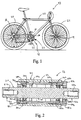
- Figure 1 is a side elevational view of a bicycle with bearing assemblies installed therein in accordance with one embodiment of the present invention;
- Figure 2 is a partial longitudinal cross-sectional view of a bottom bracket shell of the bicycle frame and a first bearing assembly, which forms the bottom bracket of the bicycle illustrated in Figure 1;
- Figure 3 is a side elevational view of the crank spindle or inner member for the first bearing assembly, which forms the bottom bracket of the bicycle illustrated in Figure 1;
- Figure 4 is a partial longitudinal cross-sectional view of the outer tubular member or shell for the first bearing assembly, which forms the bottom bracket of the bicycle illustrated in Figure 1;
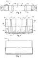
- Figure 5 is a partial longitudinal cross-sectional view of the outer tubular member or shell for the first bearing assembly, prior to being deformed;
- Figure 6 is a partial schematic longitudinal cross-sectional view of a pair of dies with the crank spindle or inner member of the first bearing assembly being deformed by cold rolling;
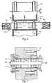
- Figure 7 is a partial schematic longitudinal cross-sectional view of a pair of dies with the outer tubular member of the first bearing assembly being deformed by cold rolling;
- Figure 8 is a partial schematic end view of the outer tubular member for the first bearing assembly being deformed by cold rolling; and
- Figure 9 is a partial longitudinal cross-sectional view of a second bearing assembly, which forms the front hub of the bicycle illustrated in Figure 1.
-
- Referring initially to Figure 1, a
bicycle 10 is illustrated with bicycle bearingassemblies Bicycle 10 basically includes abicycle frame 20 with front andrear wheels 22 rotatably coupled thereto and adrive train 23. Bicycles such asbicycle 10 are well known in the art, and thus,bicycle 10 and its various components will not be discussed or illustrated in detail herein. It will be apparent to those skilled in the art thatbicycle 10 can be any type of bicycle, e.g., mountain bike, a hybrid bike or a road bike. -
Bicycle bearing assembly 12 is illustrated as a bottom bracket, which is coupled tobottom bracket shell 24 ofbicycle frame 20.Bicycle bearing assembly 12 supports a pair ofcranks 26 for rotation relative toframe 20.Bicycle bearing assembly 14 is illustrated as a front hub, which rotatably supports one of thewheels 22 tobicycle frame 20.Bicycle bearing assembly 16 is illustrated as a rear hub or free wheel, which rotatably supports the other of thewheels 22 tobicycle frame 20. - Referring now to Figure 2, bearing
assembly 12 forms the bottom bracket ofbicycle 10 forrotatably coupling cranks 26 tobicycle frame 20. In particular,bearing assembly 12 is coupled to thebottom bracket shell 24 ofbicycle frame 20, andcranks 26 are non-rotatably coupled to the ends ofbearing assembly 12 by fixing bolts 28 (only one shown in Figure 1). Bearingassembly 12 basically includes an elongated inner member or crankspindle 30, a tubular outer member orshell 32, two sets of bearingmembers 34a and 34b, a pair of retainers orcages 36a and 36b, a pair of seals 38a and 38b and a pair of adapters 40a and 40b. - Crank
spindle 30 is designed to rotate within tubularouter member 32 via bearingmembers 34a and 34b. Accordingly, crankspindle 30 acts as an inner race, which is fixedly coupled to cranks, while tubularouter member 32 acts as an outer race, which is fixedly coupled to thebottom bracket shell 24 ofbicycle frame 20. The bearingmembers 34a and 34b are preferably steel balls with each set of bearingmembers 34a and 34b having seven steel balls therein. Of course, it will be apparent to those skilled in the art from this disclosure that fewer or more steel balls can be utilized in each set of bearingmembers 34a and 34b. - Referring now to Figure 3, crank
spindle 30 is an elongated member having afirst end 46a, a second end 46b and anouter surface 48 extending between first end 44a and second end 46b. First and second ends 46a and 46b, respectively, have axially extending threadedbores 50a and 50b for threadedly receiving one of the fixingbolts 28 to fixedly secure one of thecranks 26 thereto.Outer surface 48 along the first and second ends 46a and 46b ofcrank spindle 30 has a non-circular cross-section for non-rotatably receiving one of thecranks 26 thereon. For example,outer surface 48 along first and second ends 46a and 46b can have a plurality of flat surfaces formed thereon. Alternatively, serrations could be formed at first and second ends 46a and 46b ofcrank spindle 30. The serrations are obtained by integrally forming eight projections of an angular cross-section at circumferentially spaced positions of the first and second ends 46a and 46b. Preferably, the first and second ends 46a and 46b taper outwardly towards the free ends ofcrank spindle 30. In any event, thecranks 26 have mating internal bores for non-rotatably coupling first and second ends 46a and 46b ofcrank spindle 30 thereto. - The
crank spindle 30 has acentre section 52 located between first and second ends 46a and 46b.Centre section 52 has a pair of annular raised portions with first and secondannular grooves 54a and 54b formed therein for receivingbearing members 34a and 34b. Also a pair ofraces 56a and 56b are formed on the sides ofgrooves 54a and 54b for retainingbearing members 34a and 34b therein, respectively. As explained later in more detail,annular grooves 54a and 54b as well as the remaining portion of theouter surface 48 ofcentre section 52 is formed by cold rolling crankspindle 30 between a pair of dies 90 and 91. - The
grooves 54a and 54b ofcrank spindle 30 are grooves of a circular cross-section for supporting steel balls or bearingmembers 34a and 34b. The diameter of thegrooves 54a and 54b ofcrank spindle 30 are substantially equal to the diameter of the steel balls or bearingmembers 34a and 34b or slightly larger than the diameter of the steel balls or bearingmembers 34a and 34b. Accordingly, bearingmembers 34a and 34b can freely rotate and move about the circumference ofannular grooves 54a and 54b. - Referring now to Figure 4, a partial longitudinal cross-sectional view of the tubular outer member or
shell 32 for thefirst bearing assembly 12 is illustrated. Tubularouter member 32 has a firstopen end 58a, a second open end 58b, aninternal surface 60 and anexternal surface 62. The internal andexternal surfaces outer member 32. Preferably, tubularouter member 32 is constructed of a conventional metallic material. Tubularouter member 32 is initially a tubular orcylindrical sleeve 32a as seen in Figure 5. Thesleeve 32a is cold-rolled, as explained below, to form the profile of the tubularouter member 32 as seen in Figure 4. - In particular, the
internal surface 60 is contoured to form a pair ofcylindrical end sections 64a, 64b and three centrecylindrical sections cylindrical end sections 64a and 64b are substantially identical to each other but mirror images of each other. Each of thecylindrical end sections 64a and 64b has an annular groove 68a and 68b formed therein for engagingbearing members 34a and 34b. Preferably, the grooves 68a and 68b are grooves of a circular cross-section for supportingbearing members 34a and 34b. The diameter of the curved surfaces forming the grooves 68a and 68b are preferably identical to the diameter of the steel balls or bearingmembers 34a and 34b or slightly larger than the diameter of the steel balls or bearingmembers 34a and 34b. - Still referring to Figure 4,
external surface 62 of tubularouter member 32 has a pair of cylindrical end sections 74a, 74b and threecylindrical centre sections external surface 62 are opposite the centre cylindrical surfaces 65-67 of theinternal surface 60. In other words, when thesleeve 32a (Figure 5) is deformed to create outer tubular member 32 (Figure 4), theexternal surface 62 is deformed to correspond to the deformation of theinternal surface 60. - Referring now to Figure 2,
retainers 36a and 36b are generally annular ring-shaped members, which are preferably constructed of a synthetic resin such as the synthetic resin Duran (TM).Retainers 36a and 36b are relatively conventional members, which are well known in the art. Thus,retainers 36a and 36b will not be discussed or illustrated in detail herein. Basically,retainers 36a and 36b are formed of an annular ring-shaped portion and with seven axially extending flanges or spacers which are circumferentially spaced around the ring portion for receiving steel balls or bearingmembers 34a and 34b therebetween. Theretainers 36a and 36b serve to maintain a constant interval between the steel balls or bearingmembers 34a and 34b, the spaces between the flanges slightly exceeds the diameter of the bearing members to accommodate their rotation. - Referring again to Figure 2, seals 38a and 38b are preferably annular members constructed of a resilient and/or elastic material such as conventional rubber seals. The seals 38a and 38b are ring-shaped such that the internal diameter of the seal is slightly smaller than the
crank spindle 30. Thus, seals 38a and 38b are designed to deform around theouter surface 48 of thecrank spindle 30 to create a seal for preventing contaminants from passing between the interface thereof The outer diameters of seals 38a and 38b are preferably slightly larger than thecylindrical end sections 64a and 64b of theinternal surface 60 such that seals 38a and 38b are deformed slightly inwardly when they engage theinternal surface 60 of tubularouter member 32. Thus, contaminants are prevented from passing between the interface ofinternal surface 60 and the external surface of seals 38a and 38b. - First and second adapters 40a and 40b are slightly different from each other. However, these differences are inconsequential as they relate to the present invention. Accordingly, corresponding reference numerals will be utilized to depict corresponding parts of the first and second adapters 40a and 40b. Basically, adapters 40a and 40b are tubular members having external threads 80a and 80b, an external flange 82a and 82b, an internal flange 84a and 84b and a plurality of projections 86a and 86b.
- External threads 80a and 80b are designed to engage the internal threads of the bottom bracket shell of the
bicycle frame 20 to fixedly secure the bearingassembly 12 thereto. When adapters 40a and 40b are threaded into the bottom bracket shell of thebicycle frame 20, the external flanges 82a and 82b engage thebottom bracket shell 24 ofbicycle frame 20, while the internal flanges 84a and 82b engage the first and second ends 58a and 58b of the tubularouter member 32. In this position, axial movement of the bearingassembly 12 is prevented relative to the bottom bracket shell offrame 20. Moreover, longitudinal movement of tubularouter member 32 is also prevented. More specifically, tubularouter member 32 is sandwiched between first and second adapters 40a and 40b to prevent any axial movement relative to thebottom bracket shell 24 or crankspindle 30. Projections 86a and 86b are radially extending flanges that are equally spaced about the circumference of the internal surface of the adapters 40a and 40b. The projections 86a and 86b are designed to be engaged by a spanner at circumferential spaced apart positions for threading adapter 40a and 40b into the bottom bracket shell ofbicycle frame 20. - Referring now to Figure 6, the method of manufacturing crank
spindle 30 will now be described. First, thecrank spindle 30 is manufactured by casting the general shape of the spindle such that it has the general overall shape of the end product. Next, the rough spindle is machined to form the threaded bores 50 at each of the ends of the spindle as well as to remove any imperfections from the casting operation. Then the machined spindle is placed between a pair of dies 90 and 91 to form thegrooves 54a and 54b and theraces 56a and 56b in theouter surface 48, as schematically shown in Figure 6. - The
first die 90 is a cylindrical die with a pair ofannular bulges 92a and 92b having a circular cross-section. Thesebulges 92a and 92b are designed to form thegrooves 54a and 54b. The second die 91 can be either a stationary die or a rotating die. The second die 91 has a pair ofrecesses 93a and 93b that correspond to the location of thegrooves 54a and 54b and theraces 56a and 56b, which are being formed on theouter surface 48 ofcrank spindle 30. Therotating die 90 is move to pressannular bulges 92a and 92b against theouter surface 48 ofcrank spindle 30 to begin forminggrooves 54a and 54b. The rotation of die 90 causes crankspindle 30 to rotate therewith. Thedie 90 is moved slowly relative to die 91 such that with each rotation ofcrank spindle 30 and die 90,grooves 54a and 54b become gradually deeper and deeper. In other words, as die 90 and/or 91 rotate, thecrank spindle 30 also rotates to formgrooves 54a and 54b. Thespindle 30 and die 90 are continuously rotated until the desired depth and shape ofgroove 54a and 54b are obtained. On each side of thegrooves 54a and 54b areball races 56a and 56b, which are also formed. Therecesses 93a and 93b of second die 91 are shaped to allow ball races56a and 56b to be deformed into therecesses 93a and 93b of die 91. Once the final shape is formed, thecrank spindle 30 can be treated with normal heat treating techniques to obtain the desired hardness. - Accordingly, this procedure creates a very fine surface within the
grooves 54a and 54b. In fact, this operation performs a polishing effect along thegrooves 54a and 54b. Also, whilegrooves 54a and 54b are being formed, theball races 56a and 56b are also being simultaneously formed. This makes the pitch, parallelism and the concentricity of thegrooves 54a and 54b andball races 56a and 56b very stable. - Referring now to Figures 4, 5 and 6, the method of manufacturing tubular
outer member 32 will now be described. The tubularouter member 32 is also formed by cold rolling. First, the tubularouter member 32 is manufactured by casting asleeve 32a as seen in Figure 5. Next, therough sleeve 32a is machined to remove any imperfections and create any necessary formations needed thereon. Then, themachined sleeve 32a is cold-rolled to form its final shape as shown in Figure 4. In particular, as shown in Figure 7, themachined sleeve 32a is inserted into ajig assembly 94 to be deformed.Jig assembly 94 has a tubular bore 95 having at least three cylindrical sections for accommodating the final shape of tubularouter member 32. Now, a special formingdie 96 is inserted into the internal bore of thesleeve 32a. This special die 96 includes threerollers 97 and a conically taperedexpander 98. The threerollers 97 have external surfaces that correspond to the final profile of theinternal surface 60 of tubularouter member 32. The taperedexpander 98 is located in the centre between the threerollers 97. The rollers are spaced approximately 120° apart from each other around the axis ofexpander 98. Theexpander 98 is rotated which in turn causes the threerollers 97 to rotate about their axis, as well as to orbit or rotate about the centre axis of theexpander 98. Initially, therollers 97 merely contact the cylindrical surface of thesleeve 32a such that the first rotation barely deforms the internal surface ofsleeve 32a. Theexpander 98 is slowly moved axially so as to cause therollers 97 to move radially outwardly to begin forming theinternal surface 60 of tubularouter member 32. Theexpander 98 is moved very slowly and incrementally such that theinternal surface 60 is gradually formed with each rotation of therollers 97 about the inner diameter of theinternal surface 60 of tubularouter member 32. Once the final shape is formed, the tubularouter member 32 can be treated with normal heat treating techniques to obtain the desired hardness. - Accordingly, this procedure creates a very fine surface within the grooves 68a and 68b. In fact, this operation performs a polishing effect along the grooves 68a and 68b. This makes the pitch, parallelism and the concentricity of the grooves 68a and 68b very stable.
- Once the
crank spindle 30 and tubularouter member 32 are created in accordance with the present invention, thecrank spindle 30 is inserted into the bore of tubularouter member 32 so as to be located between theouter surface 48 ofspindle 30 and theinternal surface 60 of tubularouter member 32. In particular, the bearingmembers 34a and 34b are first positioned within thegrooves 54a and 54b and grooves 68a and 68b on one side of thespindle 30 and on one side of theinternal surface 60 of tubularouter member 32. Then, the bearingmembers 34a and 34b are moved around thegrooves 54a and 54b ofcrank spindle 30 to be substantially equally spaced apart from each other within thegrooves 54a and 54b and 68a and 68b. - Now, the
retainers 36a and 36b are inserted through the open ends 58 a and 58b of tubularouter member 32 and over theends 50a and 50b ofcrank spindle 30 to hold thebearing members 34a and 34b in their correct positions. Once the retainers are in place, seals 38a and 38b are inserted over theends 50a and 50b ofcrank spindle 30 and through the open ends 58a and 58b of tubularouter member 32. This results in the external surfaces of the seals 38a and 38b being deform against thecylindrical end sections 64a and 64b of theinternal surface 60 of the tubularouter member 32. The inner surfaces of seals 38a and 38b are also deformed against theouter surface 48 ofcrank spindle 30. - Finally, with the
crank spindle 30 and the tubularouter member 32 positioned within thebottom bracket shell 24 of thebicycle frame 20, the pair of adapters 40a and 40b are threaded into thebottom bracket shell 24 of thebicycle frame 20 to fixedly securebearing assembly 12 tobicycle frame 20. This completes the installation of the bearingassembly 12. Of course, now thecranks 26 can be installed onto thecrank spindle 30 via fixing bolts 42 in a conventional manner. - Referring now to Figure 9, a partial cross-sectional view of the
second bearing assembly 14 is illustrated in accordance with the present invention. Thissecond bearing assembly 14 is constructed in substantially the same manner as thefirst bearing assembly 12 of Figures 1-8, discussed above, except thatsecond bearing assembly 14 is a bicycle hub. In view of the similarities between second bearingassembly 14 andfirst bearing assembly 12, thesecond bearing assembly 14 will not be discussed or illustrated in detail herein. Rather, the description of the parts of thefirst bearing assembly 12, which are similar to the parts second bearingassembly 14, applies to the parts second bearingassembly 14. - Bearing
assembly 14 forms the front hub of thefront bicycle wheel 22 for rotatably couplingfront bicycle wheel 22 tobicycle frame 20. Bearingassembly 14 basically includes an elongated inner member or hub axle 130, a tubular outer member orhub shell 132, two sets of bearing members 134a and 134b, a pair of retainers orcages 136a and 136b, a pair of seals 138a and 138b and a pair of hub flanges 140a and 140b. - Hub axle 130 is designed to rotate within tubular
outer member 132 via bearing members 134a and 134b. Accordingly, hub axle 130 acts as an inner race, which is fixedly coupled toframe 20, while tubularouter member 132 acts as an outer race, which is fixedly coupled towheel 22. The bearing members 134a and 134b are preferably steel balls with each set of bearing members 134a and 134b having seven steel balls therein. Of course, it will be apparent to those skilled in the art from this disclosure that fewer or more steel balls can be utilized in each set of bearing members 134a and 134b. - Hub axle 130 is an elongated member having a first end 146a, a second end 146b and an
outer surface 148 extending between first end 144a and second end 146b. First and second ends 146a and 146b are threaded for threadedly receiving hub fasteners 128a and 128b to fixedly securewheel 22 tobicycle frame 20. While hub fasteners 128a and 128b are shown as hub nuts, it will be apparent to those skilled in the art from this disclosure that the hub fasteners can be a quick release lever and a quick release nut. - Hub axle 130 has a centre section 152 located between first and second ends 146a and 146b. Centre section 152 has a pair of annular raised portions with first and second annular grooves 154a and 154b formed therein for receiving bearing members 134a and 134b. Also a pair of races 156a and 156b are formed on the sides of grooves 154a and 154b for retaining bearing members 134a and 134b therein, respectively.
- Grooves 154a and 154b of hub axle 130 are grooves of a circular cross-section for supporting steel balls or bearing members 134a and 134b. The diameter of the grooves 154a and 54b are substantially equal to the diameter of the steel balls or bearing members 134a and 134b or slightly larger than the diameter of the steel balls or bearing members 134a and 134b. Accordingly, bearing members 134a and 314b can freely rotate and move about the circumference of annular grooves 154a and 154b.
- The tubular outer member or
hub shell 132 has a first open end 158a, a second open end 158b, aninternal surface 160 and an external surface 162. The internal andexternal surfaces 160 and 162 extend between the first and second open ends 158a and 158b of tubularouter member 132. Preferably, tubularouter member 132 is constructed of a conventional metallic material. Tubularouter member 132 is initially a tubular or cylindrical sleeve. The sleeve is cold rolled to form the profile of the tubularouter member 132 as seen in Figure 9. - In particular, the
internal surface 160 is contoured to form a pair of annular groove 168a and 168b formed therein for engaging bearing members 134a and 134b. Preferably, the grooves 168a and 168b are grooves of a circular cross-section for supporting bearing members 134a and 134b. The diameter of the curved surfaces forming the grooves 168a and 168b are preferably identical to the diameter of the steel balls or bearing members 134a and 134b or slightly larger than the diameter of the steel balls or bearing members 134a and 134b. - External surface 162 of tubular
outer member 132 has a pair of annular bulges 178a and 178b, respectively, which are located opposite annular grooves 168a and 168b. In other words, when the sleeve is deformed to create outertubular member 132, the external surface 162 is deformed to correspond to the deformation of theinternal surface 160. -
Retainers 136a and 136b are generally annular ring-shaped members, which are preferably constructed of a synthetic resin such as the synthetic resin Duran.Retainers 136a and 136b are relatively conventional members, which are well known in the art. Thus,retainers 136a and 136b will not be discussed or illustrated in detail herein. Basically,retainers 136a and 316b are formed of an annular ring-shaped portion and with seven axially extending flanges or spacers which are circumferentially spaced around the ring portion for receiving steel balls or bearing members 134a and 134b therebetween. Theretainers 136a and 136b serve to maintain a constant interval between the steel balls or bearing members 134a and 134b, the spaces between the flanges slightly exceeds the diameter of the bearing members to accommodate their rotation. - Seals 138a and 138b are preferably annular members constructed of a resilient and/or elastic material such as conventional rubber seals. The seals 138a and 138b are ring-shaped such that the internal diameter of the seal is slightly smaller than the hub axle 130. Thus, seals 138a and 138b are designed to deform around the
outer surface 148 of hub axle 130 to create a seal for preventing contaminants from passing between the interface thereof. The outer diameters of seals 138a and 138b are preferably slightly larger than theinternal surface 160 such that seals 138a and 318b are deformed slightly inwardly when they engage theinternal surface 160 of tubularouter member 132. Thus, contaminants are prevented from passing between the interface ofinternal surface 160 and the external surface of seals 138a and 138b. - Hub flanges 140a and 140b can be slightly different from each other. However, these differences are inconsequential as they relate to the present invention. Accordingly, corresponding reference numerals will be utilized to depict corresponding parts of the first and second hub flanges 140a and 140b. Basically, hub flanges 140a and 140b are tubular members that are frictionally secured on tubular outer member 130. Hub flanges 140a and 140b have outer flanges 182a and 182b and inner flanges 184a and 184b, respectively. The outer flanges 182a and 182b have a plurality of holes for coupling spokes or the like thereto. Inner flanges 184a and 184b abut against the ends of the tubular
outer member 132. - Turning now to
third bearing assembly 16,rear wheel 22 is rotatably coupled to frame 20 by thethird bearing assembly 16. Thethird bearing assembly 16 is substantially identical to thesecond bearing assembly 14 except thatthird bearing assembly 16 is a rear or free hub. Accordingly, it will be understood by those skilled in the art that the construction and method of manufacturingfirst bearing assembly 12 andsecond bearing assembly 14 can also be applied to that the construction and method of manufacturingthird bearing assembly 16. Thus, thethird bearing assembly 16 will not be discussed or illustrated in detail herein. - While several particular embodiments have been chosen to illustrate the present invention, it will be understood by those skilled in the art that various changes and modifications can be made herein without departing from the scope of the invention as defined in the appended claims. Furthermore, the foregoing description of the preferred embodiments of the present invention is provided for illustration only, and not for the purpose of limiting the invention as defined by the appended claims and their equivalents.
Claims (36)
- A bicycle bearing assembly (12,14,16), comprising:an elongated inner member (30,130) having a first end (46a,146a), a second end (46b,146b), and an outer surface (48,148) extending therebetween, with a first annular groove (54a,154a) formed in said outer surface (48,148) of said elongated inner member (30,130);a tubular outer member (32,132) having a first open end (58,158a), a second open end (58b,158b), and internal and external surfaces (60,160,62,162) extending between said first and second open ends (58a,158a,58b,158b) of said tubular outer member (32,132), with said internal surface (60,160) deformed to form a second annular groove (68a,168a) in said internal surface (60,160) of said tubular outer member (32,132) and a first annular bulge (78a,178a) in said external surface (62,162) by formation of said second annular groove (68a,168a); anda plurality of first bearing members (34a,134a) located between said first annular groove (54a,154a) of said elongated inner member (30,130) and said second annular groove (68a,168a) of said tubular outer member (32,132).
- A bicycle bearing assembly (12,14,16) according to claim 1, whereinsaid outer surface (48,148) of said elongated inner member (30,130) has a third annular groove (54b,154b) formed therein;said tubular outer member (32,132) has a fourth annular groove (68b,168b) formed in said internal surface (60,160) of said tubular outer member (32,132) and a second annular bulge (78b,178b) in said external surface (62,162) of said tubular outer member (32,132) by formation of said fourth annular groove (68b,168b); anda plurality of second bearing members (34b,134b) located between said third annular groove (54b,154b) of said elongated inner member (30,130) and said fourth annular groove (68b, 168b) of said tubular outer member (32,132).
- A bicycle bearing assembly (12) according to claim 2, wherein saidelongated inner member is a crank spindle (30) with said first and second ends (46a,46b) being configured to rotatably couple bicycle cranks (26) thereto.
- A bicycle bearing assembly (12) according to claim 3, further comprisinga first annular adapter (40a) having external threads (80a) and an internal flange (84a) abutting said first end (58a) of said tubular outer member (32).
- A bicycle bearing assembly (12) according to claim 4, further comprisinga second annular adapter (40b) having external threads (80b) and an internal flange (84b) abutting said second end (58b) of said tubular outer member (32).
- A bicycle bearing assembly (14,16) according to claim 2, wherein said elongated inner member is a hub axle (130) with said first and second ends (146a,146b) being configured to be fixedly coupled to a portion of a bicycle frame (20), and said tubular outer member is a hub shell (132).
- A bicycle bearing assembly (14,16) according to claim 6, further comprisinga first annular hub flange (140a) having an outer connecting flange (182a) and an inner flange (184a) abutting said first end (146a) of said tubular outer member (132).
- A bicycle bearing assembly (14,16) according to claim 7, further comprisinga second annular hub flange (140b) having an outer connecting flange (182b) and an inner flange (184b) abutting said second end (146b) of said tubular outer member (132).
- A bicycle bearing assembly (12,14,16) according to any of claims 2 to 8, further comprising first and second annular seals (38a,138a,38b,138b) located between said outer surface (48,148) of said elongated inner member (30,130) and said internal surface (60,160) of said tubular outer member (32,132).
- A bicycle bearing assembly (12,14,16) according to any of claims 2 to 9, wherein said annular grooves (54a,54b,154a,154b) of said elongated inner member (30,130) have a curved surface in axial cross section, and said annular grooves (68a,68b,168a,168b) of said tubular outer member (32,132) have a curved surface in axial cross section.
- A bicycle bearing assembly (12,14,16) according to any of claims 2 to 10, wherein said first and second bearing members (34a,134a,34b,134b) are rolling elements with a predetermined rolling diameter.
- A bicycle bearing assembly (12,14,16) according to claim 11, whereinsaid curved surfaces of said annular grooves (54a,54b,154a,154b,68a,68b,168a,168b) of said elongated inner member (30,130) and said tubular outer member (32,132) have predetermined diameters which are at least as large as said predetermined rolling diameters of said first and second bearing members (34a,134a,34b,134b).
- A bicycle bearing assembly (12,14,16) according to any preceding claim, further comprising a first hub fastening member (28,128a) coupled to said first end (46,146a) of said elongated inner member (30,130) and a second hub fastening member (28,128b) coupled to said second end (46b,146b) of said elongated inner member (30,130).
- An outer race for a bicycle bearing assembly (12,14,16), comprising:a first open end (58a,158a);a second open end (58b,158b); anda tubular member (32,132) with internal and external surfaces (60,160,62,162) extending between said first and second open ends (58a,158a,58b,158b), said internal surface (60,160) deformed to form a first annular groove (68a,168a) in said internal surface (60,160) and a first annular bulge (78a,178a) in said external surface (62,162) by formation of said first annular groove (68a,168a).
- An outer race for a bicycle bearing assembly (12,14,16) according to claim 14, wherein said tubular member (32,132) has a second annular groove (68b,168b) formed in said internal surface (60,160) and a second annular bulge (78b,178b) in said external surface (62,162) by formation of said second annular groove (68b,168b).
- An outer race for a bicycle bearing assembly (12,14,16) according to claim 15, wherein said annular grooves (68a,68b,168a,168b) of said tubular member (32,132) have a curved surface in axial cross section.
- An outer race for a bicycle bearing assembly (12,14,16) according to either claim 15 or claim 16, wherein said first annular groove (68a,168a) of said tubular member (32,132) is located adjacent said first open end (58a,158a) and said second annular groove (68b,168b) of said tubular member (32,132) is located adjacent said second open end (58b, 158b).
- An outer race for a bicycle bearing assembly (12,14,16) according to any of claims 15 to 17, wherein said first annular groove (68a,168a) of said tubular member (32,132) is substantially identical to said second annular groove (68b,168b) of said tubular member (32,132).
- A method of forming a bicycle bearing assembly (12,14,16), comprising the steps of:forming an elongated inner member (30,130) having a first end (46a,146a), a second end (46b,146b) and an outer surface (48,148) extending therebetween;forming a first annular groove (54a,154a) in said outer surface (48,148) of said inner member (30,130);forming a tubular outer member (32,132) having a first open end (58a, 158a), a second open end (58b, 158b) and internal and external surfaces (60,62,160,162) extending between said first and second open ends (58a,58b,158a,158b) of said tubular outer member (32,132);deforming said internal surface (60,160) of said tubular outer member (32,132) by rolling to form a second annular groove (68a,168a) in said internal surface (60,160) of said tubular outer member (32,132) and forming a first annular bulge (78a,178a) in said external surface (62,162) of said tubular outer member (32,132) by formation of said second annular groove (68a,168a); andinserting a plurality of first bearing members (34a,134a) located between said first annular groove (54a,154a) of said elongated inner member (30,130) and said second annular groove (68a,168a) of said tubular outer member (32,132).
- A method of forming a bicycle bearing assembly (12,14,16) according to claim 19, and further comprising the steps of forming a third annular groove (54b,154b) in said outer surface (48,148) of said elongated inner member (30,130);deforming said internal surface (60,160) of said tubular outer member (32,132) by rolling to form a fourth annular groove (68b,168b) in said internal surface (60,160) of said tubular outer member (32,132) and a second annular bulge (78b,178b) in said external surface (62,162) of said tubular outer member (32,132) by formation of said fourth annular groove (68b,168b); andinserting a plurality of second bearing members (34b,134b) between said third annular groove (54b,154b) of said elongated inner member (30,130) and said fourth annular groove (68b,168b) of said tubular outer member (32,132).
- A method of forming a bicycle bearing assembly (12) according to claim 20, and further comprising the step of forming said elongated inner member as a crank spindle (30) with said first and second ends (46a,46b) being configured to rotatably couple bicycle cranks (26) thereto.
- A method of forming a bicycle bearing assembly (12) according to claim 21, and further comprising the step of adding a first annular adapter (40a) onto said first end (58a) of said tubular outer member (32), said first annular adapter (40a) having an internal flange (84a) and external threads (80a) thereon.
- A method of forming a bicycle bearing assembly (12) according to claim 22, and further comprising the step of adding a second annular adapter (40b) onto said second end (58b) of said tubular outer member (32), said second annular adapter (40b) having an internal flange (84b) and external threads (80b) thereon.
- A method of forming a bicycle bearing assembly (14,16) according to claim 20, and further comprising the steps offorming said elongated inner member as a hub axle (130) with said first and second ends (146a,146b) being configured to be fixedly coupled to a portion of a bicycle frame (20), and forming said tubular outer member as a hub shell (132).
- A method of forming a bicycle bearing assembly (14,16) according to claim 24, and further comprising the step of adding a first annular hub flange (140a) onto said first end (146a) of said tubular outer member (132), said first annular hub flange (140a) having an inner flange (184a) and an outer connecting flange (182a).
- A method of forming a bicycle bearing assembly (14,16) according to claim 25, and further comprising the step of adding a second annular hub flange (140b) onto said second end (146b) of said tubular outer member (132), said second annular hub flange (140b) having an inner flange (184b) and an outer connecting flange (182b).
- A method of forming a bicycle bearing assembly (12,14,16) according to any of claims 20 to 26, and further comprising the step of adding first and second annular seals (38a,138a,38b,138b) between said outer surface (48,148) of said elongated inner member (30,130) and said internal surface (60,160) of said tubular outer member (32,132).
- A method of forming a bicycle bearing assembly (12,14,16) according to any of claims 20 to 27, whereinsaid annular grooves (54a,54b,154a,154b) of said elongated inner member have a curved surface in axial cross section, and said annular grooves (68a,68b,168a,168b) of said tubular outer member (32,132) have a curved surface in axial cross section.
- A method of forming a bicycle bearing assembly (12,14,16) according to any of claims 20 to 28, wherein said first and second bearing members (34a,134a,34b,134b) are rolling elements with a predetermined rolling diameter.
- A method of forming a bicycle bearing assembly (12,14,16) according to claim 29, whereinsaid curved surfaces of said annular grooves (54a,54b,154a,154b,68a,168a,168b) of said elongated inner member (30,130) and said tubular outer member (32,132) have predetermined diameters which are at least as large as said predetermined rolling diameters of said first and second bearing members (34a,134a,34b,134b).
- A method of forming a bicycle bearing assembly (12,14,16) according to any of claims 19 to 30, and further comprising the steps ofadding a first hub fastening member (28,128a) coupled to said first end (46a,146a) of said elongated inner member (30,130) and a second hub fastening member (28,128b) coupled to said second end (46b,146b) of said elongated inner member (30,130).
- A method of forming an outer race for a bicycle bearing assembly (12,14,16), comprising the steps of:forming a tubular outer member (32,132) having a first open end (58a, 158a), a second open end (58b, 158b) and internal and external surfaces (60,160,62,162) extending between said first and second open ends (58a,158a,58b,158b) of said tubular outer member (32,132); anddeforming said internal surface (60,160) of said tubular outer member (32,132) by rolling to form a first annular groove (68a,168a) in said internal surface (60,160) of said tubular outer member (32,132) and forming a first annular bulge (78a,178a) in said external surface (62,162) of said tubular outer member (32,132) by formation of said first annular groove (68a,168a).
- A method of forming an outer race for a bicycle bearing assembly (12,14,16) according to claim 32, and further comprising the step ofdeforming said internal surface (60,160) of said tubular outer member (32,132) by rolling to form a second annular groove (68b,168b) in said internal surface (60,160) of said tubular outer member (32,132) and a second annular bulge (78b,178b) in said external surface (62,162) of said tubular outer member (32,132) by formation of said second annular groove (68,168b).
- A method of forming an outer race for a bicycle bearing assembly (12,14,16) according to claim 33, whereinsaid annular grooves (68a,68b,168a,168b) of said tubular member (32,132) have a curved surface in axial cross section.
- A method of forming an outer race for a bicycle bearing assembly (12,14,16) according to either claim 33 or claim 34, whereinsaid first annular groove (68a,168a) of said tubular member (32,132) is located adjacent said first open end (58,158a) and said second annular groove (68b,168b) of said tubular member (32,132) is located adjacent said second open end (58b,158b).
- A method of forming an outer race for a bicycle bearing assembly (12,14,16) according to any of claims 33 to 35, and further comprising the step ofsaid first annular groove (68a,168a) of said tubular member (32,132) is substantially identical to said second annular groove (68b,168b) of said tubular member (32,132).
Applications Claiming Priority (2)
| Application Number | Priority Date | Filing Date | Title |
|---|---|---|---|
| US108246 | 1998-07-01 | ||
| US09/108,246 US5984528A (en) | 1998-07-01 | 1998-07-01 | Bearing assembly for bicycle parts |
Publications (3)
| Publication Number | Publication Date |
|---|---|
| EP0968908A2 true EP0968908A2 (en) | 2000-01-05 |
| EP0968908A3 EP0968908A3 (en) | 2000-11-08 |
| EP0968908B1 EP0968908B1 (en) | 2006-04-26 |
Family
ID=22321091
Family Applications (1)
| Application Number | Title | Priority Date | Filing Date |
|---|---|---|---|
| EP99303636A Expired - Lifetime EP0968908B1 (en) | 1998-07-01 | 1999-05-10 | Bearing assembly for bicycle parts |
Country Status (6)
| Country | Link |
|---|---|
| US (2) | US5984528A (en) |
| EP (1) | EP0968908B1 (en) |
| JP (1) | JP3445946B2 (en) |
| CN (2) | CN1106973C (en) |
| DE (1) | DE69930990T2 (en) |
| TW (1) | TW442422B (en) |
Families Citing this family (33)
| Publication number | Priority date | Publication date | Assignee | Title |
|---|---|---|---|---|
| USD501138S1 (en) | 1998-03-31 | 2005-01-25 | Fuji Photo Film Co., Ltd. | Portion of a plug and container cap |
| JP2000314428A (en) * | 1999-04-30 | 2000-11-14 | Nsk Ltd | Double row ball bearing |
| US6139192A (en) * | 1999-07-21 | 2000-10-31 | Chiang; Douglas | Bicycle axle |
| US6290304B1 (en) | 2000-05-03 | 2001-09-18 | Charles Mark Lashinske | Quick connect/release wheel and hub assembly |
| TW534067U (en) * | 2000-12-22 | 2003-05-21 | Yi-Cheng Ji | Improved structure for spindle featuring with easy assembly and high stability |
| ITGE20010024A1 (en) * | 2001-03-09 | 2002-09-09 | Alberto Balbo | PORTABLE CHAMBER MINI-BIKE. |
| GB2385641B (en) * | 2002-02-19 | 2005-07-27 | Lloyd Townsend | Internal assembly semi-cartridge bottom bracket |
| US7059686B2 (en) * | 2003-01-22 | 2006-06-13 | Shimano Inc. | Bicycle hub |
| ATE471274T1 (en) * | 2005-12-02 | 2010-07-15 | Campagnolo Srl | CRANK UNIT FOR THE BOTTOM BEARING, DRIVE SHAFT AND PEDAL CRANK OF A BICYCLE |
| ATE524374T1 (en) * | 2006-02-20 | 2011-09-15 | Campagnolo Srl | BICYCLE BOTTOM BEARING |
| EP1829779B1 (en) * | 2006-03-03 | 2011-01-12 | CAMPAGNOLO S.r.l. | Bicycle bottom bracket assembly and adapter device for such an assembly |
| JP2007297040A (en) | 2006-05-04 | 2007-11-15 | Campagnolo Spa | Crank arm assembly for bicycle |
| DE102006029221A1 (en) * | 2006-06-26 | 2007-12-27 | Robert Bosch Gmbh | Fastening device for use in electrical machine, has plate nut provided as axial stop for roller bearing, and thread arranged at outer circumference of plate nut, where nut covers surface of bearing in mounted condition |
| US7520523B1 (en) * | 2006-10-02 | 2009-04-21 | Dighans Dennis B | Bicycle stunt peg apparatus |
| US8721187B2 (en) * | 2007-04-06 | 2014-05-13 | Shimano Inc. | Bicycle axle assembly |
| DE202007016253U1 (en) * | 2007-11-21 | 2009-04-02 | Canyon Bicycles Gmbh | Fahrradtretlagereinrichtung and bicycle frame |
| ITMI20070406U1 (en) * | 2007-12-05 | 2009-06-06 | Campagnolo Srl | ASSEMBLY OF CENTRAL MOVEMENT OF BICYCLE AND TREE FOR A SUCH ASSEMBLY |
| EP2110301B1 (en) * | 2008-04-17 | 2014-12-24 | CAMPAGNOLO S.r.l. | Assembly of bicycle components in mutual rotation and bicycle comprising such an assembly |
| DE102008021803A1 (en) * | 2008-04-30 | 2009-11-05 | Dt Swiss Ag | Hub, especially for bicycles |
| US20100322546A1 (en) * | 2009-06-22 | 2010-12-23 | Jeroen Bosboom | Freehub ball bearing carrier |
| KR101231199B1 (en) * | 2010-06-07 | 2013-02-07 | 임영규 | Double interlocking speed change bicycle at middle |
| CN102717072A (en) * | 2012-05-30 | 2012-10-10 | 自贡硬质合金有限责任公司 | Die and die assembly method |
| EP2939915A4 (en) * | 2012-12-26 | 2016-10-19 | Gokiso Giken Co Ltd | Bicycle crank shaft device |
| US20140319797A1 (en) * | 2013-04-24 | 2014-10-30 | Pacific Cycle, Llc | Quick-release bicycle crank assembly |
| US9228613B2 (en) | 2014-02-24 | 2016-01-05 | Shimano Inc. | Bicycle bottom bracket assembly |
| CN104565009A (en) * | 2014-12-26 | 2015-04-29 | 无锡市利钧轴承有限公司 | Crankshaft bearing |
| CN106043578A (en) * | 2016-06-19 | 2016-10-26 | 重庆奇可比自行车有限公司 | Intermediate shaft of bicycle driven by forward and reverse rotation of pedals |
| DE102016211690A1 (en) | 2016-06-29 | 2018-01-04 | Aktiebolaget Skf | Fahrradwälzlagerung |
| JP6753752B2 (en) * | 2016-09-30 | 2020-09-09 | 株式会社シマノ | Support structure of electric motor for bicycle and drive unit for bicycle including this |
| TWI643783B (en) * | 2018-04-24 | 2018-12-11 | 林昌慧 | Inner bushing structure of five-way pipe |
| KR102218794B1 (en) * | 2018-08-07 | 2021-02-22 | 선상규 | a stator and an inner rotor of a generator for use with a rotary shaft |
| DE102018216496A1 (en) * | 2018-09-26 | 2020-03-26 | Aktiebolaget Skf | Motor vehicle wheel or motorcycle swing roller bearing |
| CN112392860B (en) * | 2020-11-16 | 2021-08-06 | 江苏吉达粉体工程设计研究院有限公司 | Nut bearing seat |
Citations (1)
| Publication number | Priority date | Publication date | Assignee | Title |
|---|---|---|---|---|
| US4150859A (en) | 1975-10-17 | 1979-04-24 | Shimano Industrial Company, Ltd. | Chain wheel and crank for a bicycle |
Family Cites Families (15)
| Publication number | Priority date | Publication date | Assignee | Title |
|---|---|---|---|---|
| US628791A (en) * | 1897-04-16 | 1899-07-11 | Eugene Germaine | Hub for wheels of velocipedes, &c. |
| US2146663A (en) * | 1937-09-21 | 1939-02-07 | Vaughn David Coulter | Antifriction bearing for connecting rods |
| FR1124162A (en) * | 1955-03-28 | 1956-10-05 | Nofoda | Improvements to annular hubs, especially for cycles |
| US3579782A (en) * | 1968-08-02 | 1971-05-25 | Stig Lennart Hallerback | Method of manufacturing rolling bearing components |
| JPS567713A (en) * | 1979-06-29 | 1981-01-27 | Asahi Chem Ind Co Ltd | Oily main drug preparation composition |
| SE461606B (en) * | 1988-02-11 | 1990-03-05 | Skf Nova Ab | PROCEDURES FOR PREPARING TWO-LINE ANGLE CONTACT BALLS |
| DE3821051A1 (en) * | 1988-06-22 | 1989-12-28 | Skf Gmbh | Bearing outer race, especially the outer race of a two-row angular contact ball bearing, secured in the bore of a housing |
| CN2063108U (en) * | 1989-07-29 | 1990-10-03 | 邹爽 | Hydraulic transmission device for bicycle |
| DE4024426A1 (en) * | 1990-08-01 | 1992-02-06 | Robert Schmitt | UNIVERSAL BICYCLE PRECISION BOTTOM BEARING UNIT |
| DE9014394U1 (en) * | 1990-10-17 | 1991-01-03 | Skf Gmbh, 97421 Schweinfurt | Sealing for bearings, especially for pedal axle bearings of bicycles |
| JPH0475792U (en) * | 1990-11-14 | 1992-07-02 | ||
| US5181437A (en) * | 1992-07-13 | 1993-01-26 | Chi Yi C | Hub of a bicycle |
| US5473962A (en) * | 1994-03-28 | 1995-12-12 | Yamamoto; Teiji | Bicycle hanger structure |
| DE19604194B4 (en) * | 1996-02-06 | 2004-09-30 | Skf Gmbh | Hub for two-wheel vehicles |
| DE19607310A1 (en) * | 1996-02-27 | 1997-08-28 | Dietrich Gerhard Ellsaesser | Inner bearing forming method for bicycle wheel's crank |
-
1998
- 1998-07-01 US US09/108,246 patent/US5984528A/en not_active Expired - Fee Related
-
1999
- 1999-05-10 DE DE69930990T patent/DE69930990T2/en not_active Expired - Lifetime
- 1999-05-10 EP EP99303636A patent/EP0968908B1/en not_active Expired - Lifetime
- 1999-06-22 TW TW088110489A patent/TW442422B/en not_active IP Right Cessation
- 1999-06-25 JP JP17967499A patent/JP3445946B2/en not_active Expired - Fee Related
- 1999-06-30 CN CN99110112A patent/CN1106973C/en not_active Expired - Fee Related
- 1999-06-30 CN CNB021245924A patent/CN1309965C/en not_active Expired - Fee Related
- 1999-07-23 US US09/359,682 patent/US6212774B1/en not_active Expired - Lifetime
Patent Citations (1)
| Publication number | Priority date | Publication date | Assignee | Title |
|---|---|---|---|---|
| US4150859A (en) | 1975-10-17 | 1979-04-24 | Shimano Industrial Company, Ltd. | Chain wheel and crank for a bicycle |
Also Published As
| Publication number | Publication date |
|---|---|
| US5984528A (en) | 1999-11-16 |
| CN1241690A (en) | 2000-01-19 |
| EP0968908B1 (en) | 2006-04-26 |
| DE69930990T2 (en) | 2007-05-10 |
| DE69930990D1 (en) | 2006-06-01 |
| EP0968908A3 (en) | 2000-11-08 |
| US6212774B1 (en) | 2001-04-10 |
| CN1491817A (en) | 2004-04-28 |
| JP3445946B2 (en) | 2003-09-16 |
| CN1309965C (en) | 2007-04-11 |
| CN1106973C (en) | 2003-04-30 |
| JP2000118475A (en) | 2000-04-25 |
| TW442422B (en) | 2001-06-23 |
Similar Documents
| Publication | Publication Date | Title |
|---|---|---|
| US5984528A (en) | Bearing assembly for bicycle parts | |
| EP0849481B1 (en) | Expandable bearing retainer | |
| EP1691090B1 (en) | Bearing device for wheel | |
| US8914965B2 (en) | Processing method for brake rotor-equiped wheel bearing devices | |
| EP1196261B1 (en) | A method of machining a hub bearing unit for a wheel of a motor vehicle | |
| US6866422B2 (en) | Bearing-hub unit for motor vehicle wheel | |
| JP3650746B2 (en) | Wheel bearing fixed structure and wheel bearing | |
| JP2008138865A (en) | Bearing device for wheel | |
| US20060110087A1 (en) | Bearing unit for wheel and method of fabricating the same | |
| WO2007091408A1 (en) | Wheel-use bearing device | |
| CN101309804A (en) | Complete bearing assembly and assembly method thereof | |
| JP2001010304A (en) | Hub unit for supporting wheels and method of assembling the same | |
| US7441842B2 (en) | Bicycle hub | |
| JP4693752B2 (en) | Manufacturing method of wheel bearing device | |
| JP2005106213A (en) | Outer ring for rolling bearing device | |
| JP4627017B2 (en) | Wheel bearing device | |
| US7464469B2 (en) | Vehicle bearing wheel unit | |
| JP2003056580A (en) | Bearing device for axle | |
| JP7701776B2 (en) | Wheel bearing device and method for manufacturing the wheel bearing device | |
| JP7800198B2 (en) | Hub unit bearing and method of manufacturing the same | |
| JP2007292142A (en) | Wheel support bearing unit | |
| JP2008162322A (en) | Bearing device for wheel | |
| JP2008169875A (en) | Wheel bearing device | |
| JP2008128380A (en) | Wheel bearing device |
Legal Events
| Date | Code | Title | Description |
|---|---|---|---|
| PUAI | Public reference made under article 153(3) epc to a published international application that has entered the european phase |
Free format text: ORIGINAL CODE: 0009012 |
|
| AK | Designated contracting states |
Kind code of ref document: A2 Designated state(s): DE FR GB IE IT NL |
|
| AX | Request for extension of the european patent |
Free format text: AL;LT;LV;MK;RO;SI |
|
| PUAL | Search report despatched |
Free format text: ORIGINAL CODE: 0009013 |
|
| AK | Designated contracting states |
Kind code of ref document: A3 Designated state(s): AT BE CH CY DE DK ES FI FR GB GR IE IT LI LU MC NL PT SE |
|
| AX | Request for extension of the european patent |
Free format text: AL;LT;LV;MK;RO;SI |
|
| 17P | Request for examination filed |
Effective date: 20001130 |
|
| AKX | Designation fees paid |
Free format text: DE FR GB IE IT NL |
|
| 17Q | First examination report despatched |
Effective date: 20030603 |
|
| GRAP | Despatch of communication of intention to grant a patent |
Free format text: ORIGINAL CODE: EPIDOSNIGR1 |
|
| RAP1 | Party data changed (applicant data changed or rights of an application transferred) |
Owner name: SHIMANO INC. |
|
| GRAS | Grant fee paid |
Free format text: ORIGINAL CODE: EPIDOSNIGR3 |
|
| GRAA | (expected) grant |
Free format text: ORIGINAL CODE: 0009210 |
|
| AK | Designated contracting states |
Kind code of ref document: B1 Designated state(s): DE FR GB IE IT NL |
|
| REG | Reference to a national code |
Ref country code: GB Ref legal event code: FG4D |
|
| PG25 | Lapsed in a contracting state [announced via postgrant information from national office to epo] |
Ref country code: IE Free format text: LAPSE BECAUSE OF NON-PAYMENT OF DUE FEES Effective date: 20060510 |
|
| REG | Reference to a national code |
Ref country code: IE Ref legal event code: FG4D |
|
| REF | Corresponds to: |
Ref document number: 69930990 Country of ref document: DE Date of ref document: 20060601 Kind code of ref document: P |
|
| PG25 | Lapsed in a contracting state [announced via postgrant information from national office to epo] |
Ref country code: GB Free format text: LAPSE BECAUSE OF NON-PAYMENT OF DUE FEES Effective date: 20060726 |
|
| RAP2 | Party data changed (patent owner data changed or rights of a patent transferred) |
Owner name: SHIMANO INC. |
|
| NLT2 | Nl: modifications (of names), taken from the european patent patent bulletin |
Owner name: SHIMANO INC. Effective date: 20060802 |
|
| ET | Fr: translation filed | ||
| GBPC | Gb: european patent ceased through non-payment of renewal fee |
Effective date: 20060726 |
|
| PLBE | No opposition filed within time limit |
Free format text: ORIGINAL CODE: 0009261 |
|
| STAA | Information on the status of an ep patent application or granted ep patent |
Free format text: STATUS: NO OPPOSITION FILED WITHIN TIME LIMIT |
|
| 26N | No opposition filed |
Effective date: 20070129 |
|
| PGFP | Annual fee paid to national office [announced via postgrant information from national office to epo] |
Ref country code: NL Payment date: 20080501 Year of fee payment: 10 |
|
| NLV4 | Nl: lapsed or anulled due to non-payment of the annual fee |
Effective date: 20091201 |
|
| PG25 | Lapsed in a contracting state [announced via postgrant information from national office to epo] |
Ref country code: NL Free format text: LAPSE BECAUSE OF NON-PAYMENT OF DUE FEES Effective date: 20091201 |
|
| REG | Reference to a national code |
Ref country code: FR Ref legal event code: PLFP Year of fee payment: 17 |
|
| PGFP | Annual fee paid to national office [announced via postgrant information from national office to epo] |
Ref country code: DE Payment date: 20150506 Year of fee payment: 17 |
|
| PGFP | Annual fee paid to national office [announced via postgrant information from national office to epo] |
Ref country code: FR Payment date: 20150508 Year of fee payment: 17 Ref country code: IT Payment date: 20150515 Year of fee payment: 17 |
|
| REG | Reference to a national code |
Ref country code: DE Ref legal event code: R119 Ref document number: 69930990 Country of ref document: DE |
|
| PG25 | Lapsed in a contracting state [announced via postgrant information from national office to epo] |
Ref country code: IT Free format text: LAPSE BECAUSE OF NON-PAYMENT OF DUE FEES Effective date: 20160510 |
|
| REG | Reference to a national code |
Ref country code: FR Ref legal event code: ST Effective date: 20170131 |
|
| PG25 | Lapsed in a contracting state [announced via postgrant information from national office to epo] |
Ref country code: DE Free format text: LAPSE BECAUSE OF NON-PAYMENT OF DUE FEES Effective date: 20161201 Ref country code: FR Free format text: LAPSE BECAUSE OF NON-PAYMENT OF DUE FEES Effective date: 20160531 |