EP0968919B1 - Procédé et dispositif d'enveloppement d'objets quadrangulaires avec un matériau d'emballage sous forme de bande - Google Patents
Procédé et dispositif d'enveloppement d'objets quadrangulaires avec un matériau d'emballage sous forme de bande Download PDFInfo
- Publication number
- EP0968919B1 EP0968919B1 EP99111011A EP99111011A EP0968919B1 EP 0968919 B1 EP0968919 B1 EP 0968919B1 EP 99111011 A EP99111011 A EP 99111011A EP 99111011 A EP99111011 A EP 99111011A EP 0968919 B1 EP0968919 B1 EP 0968919B1
- Authority
- EP
- European Patent Office
- Prior art keywords
- web
- article
- arrangement
- material web
- wrapped
- Prior art date
- Legal status (The legal status is an assumption and is not a legal conclusion. Google has not performed a legal analysis and makes no representation as to the accuracy of the status listed.)
- Expired - Lifetime
Links
Images
Classifications
-
- B—PERFORMING OPERATIONS; TRANSPORTING
- B65—CONVEYING; PACKING; STORING; HANDLING THIN OR FILAMENTARY MATERIAL
- B65B—MACHINES, APPARATUS OR DEVICES FOR, OR METHODS OF, PACKAGING ARTICLES OR MATERIALS; UNPACKING
- B65B11/00—Wrapping, e.g. partially or wholly enclosing, articles or quantities of material, in strips, sheets or blanks, of flexible material
- B65B11/06—Wrapping articles, or quantities of material, by conveying wrapper and contents in common defined paths
- B65B11/08—Wrapping articles, or quantities of material, by conveying wrapper and contents in common defined paths in a single straight path
- B65B11/10—Wrapping articles, or quantities of material, by conveying wrapper and contents in common defined paths in a single straight path to fold the wrappers in tubular form about contents
Definitions
- the present invention relates to a device for wrapping cuboid objects with a web-shaped wrapping material according to the preamble of claim 1.
- a device of this type is known from EP-A-0 120 251 and the corresponding one U.S. Patent No. 4,738,078.
- a leadership facility guides the material web, forming a material web loop along the rear side of the Subject and simultaneously forms a first material web section and on the other hand one on the rear side of the object extending second material web section, the length of which is greater than the dimension of the object in the longitudinal direction of this second Material web section.
- the tensioned material web sections are held by means of holding arrangements that have needles that the Pierce the web of material.
- the material web is then by means of a stationary cutting device between the two holding arrangements severed.
- the object When rotating the pad, the object is only by its own weight and the tensioned and held second material web section held. On the one hand, this requires a certain material web Strength and on the other hand, in order to enable a quick turning, the arranging the object at least approximately centrally on the support table, so that its axis of rotation is at least approximated by the The focus of the subject is.
- the wrapped object is also during the rotation of the table kept compressed between this and the printing device, which, on the one hand, leads to a rich concern for the material web on Object leads and on the other hand a very fast rotation of the pad allows even if the object is eccentric with respect to the axis of rotation is arranged.
- the material web must continue when turning the pad no longer assume holding forces for the object.
- the support table two spaced apart and independent printing devices controlled from each other at a distance from the support table assigned. This allows the introduction of another one too wrapping object between the support table and one of the Printing facilities, while another already wrapped, between object arranged on the support table and the other printing device is conveyed away from the support table. You can use these items have different dimensions.
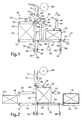
- the device shown in the figures for wrapping cuboid Objects 10, 10 'with a web-shaped wrapping material 12, has a conveyor 14 with three series-connected belt conveyors 16, 18 and 20 on. These define a movement path 22 for the objects 10, 10 'to be wrapped.
- the middle belt conveyor 18 of the three belt conveyors forms a support table 24, which is arranged around a center, in the vertical direction and at right angles to the trajectory 22 axis 26 is rotatable.
- On schematically indicated rotary drive 28 is intended to support the table 24 each by 180 °.
- Each of these printing devices 30, 32 has one in the vertical direction extending, attached to the frame part guide rail 34 on the an endless printing belt 38 guided around rollers 36 by means of a schematic indicated drive 40 is mounted adjustable in height.
- the two Printing tapes 38 of the printing devices 30, 32 are individual in their Height and thus adjustable in its distance from the second belt conveyor 18, but reversibly driven synchronously with the second belt conveyor 18.
- Each of the printing devices 30, 32 forms with the second belt conveyor 18 a folding channel 42 for U-shaped folding of the wrapping material 12 around the object to be wrapped 10.
- the in the longitudinal direction of the second belt conveyor 18 measured length of the printing devices 30, 32 is less than the length of the second belt conveyor 18 minus that in Length of the second belt conveyor 18 measured length of largest object to be wrapped 10. Further is the regarding Axle 26 in the radial direction of the roller 36 located vertically above the associated deflection roller 44 of the second belt conveyor 18.
- the support table 24 has both ends and below the second Belt conveyor 18 a holding device designed as a vacuum bar 46 48 on.
- the distance between the first belt conveyor 16 and the second belt conveyor 18 on the one hand and this and the third belt conveyor 20 on the other is as small as possible but chosen such that the second belt conveyor 18 can be rotated about the axis 26.
- first belt conveyor 16 located first belt conveyor 16 is another printing device 50 assigned.
- This has a further vertical guide rail 52 further pressure band adjustable in height by means of a drive 40 ' 54, which is guided around further rollers 56.
- This other print ribbon 54 and the first belt conveyor 16 form for each to be wrapped Item 10 a press channel 58.
- a vacuum bar 46 trained further holding device 48 'arranged stationary.
- a dash-dotted line runs through it in the vertical direction V. Path of movement 60 of a guide device 62.
- the two side by side Deflection rollers 64 having a parallel-axis guide device 62 is of a rest position 66 shown in FIG located above the highest position of the printing tapes 38, 54 in vertical direction downwards, in a separation position shown in FIG. 7 66 'and movable back again.
- the separation position 66 ' is located below the holding devices 48 and 48 '.
- the web-shaped wrapping material 12 is from one above the conveyor 14 and the printing devices 30, 32, 50 arranged supply roll 68 deducted.
- the material web runs from the supply roll 68 70, forming supply loops around a plurality of stationary rollers 72 and in between arranged dancer rollers 74.
- the free end of the material web 70 runs with a first material web section 76, the movement path 22 of the object 10 to be wrapped crossing between the first and second belt conveyor 16, 18, and is at the free end region held by the stationary holding device 48 '.
- the objects to be wrapped are 10, 10 'around stacks of different heights of printed matter, such as newspapers, magazines or the like.
- wrapping material 12 is a self-adhesive plastic film.
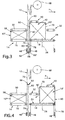
- the first Belt conveyor 16 facing printing device 30 of the support table 24 is at the level of the further printing device 50 by means of the drive 40 set.
- the guide device 62 moved from its rest position 66 into the separation position 66 '.
- the material web 70 becomes a material web loop 80 along the rear side 82 of the object as seen in the conveying direction F. 10 to below the conveyor 14 and the corresponding Holding devices 48, 48 'passed through; see also FIG. 3.
- FIG. 7 shows the separation position 66 'of the guide device 62.
- the material web 70 was vacuumed on both applied vacuum bar 46, whereby the material web 70th is captured.
- a schematically indicated machine frame 84 on which in a manner not shown but generally known the other parts of the device are arranged is a U-shaped in cross section Support element 86 attached. Between the leg ends of the support element 86 and the deflection rollers 64 of the guide device 62 the web of material 70 is clamped.
- the guide device 62 has a cutting knife 88 which consists of a 6 retracted position shown approximately at the level of the axes of the Deflection rollers 64 in a downward direction into one shown in FIG. 7 Cutting position over the lower tangent to the two deflecting rollers 64 is slidable through it. With this movement, the clamped Material web 70 in the first material web section 76 and a second Material web section 90 separated with the end section 78.
- the vacuum bars 46 have one hollow, cross-sectionally rectangular beams, whose interior with a schematically indicated vacuum source 92 is connected, and the side of the material web 70 facing a plurality of Through holes is provided.
- the input side of the first belt conveyor 16 is another in FIG. 2 Object 10 ", on which a cover sheet lies, is shown.
- the further printing device 50 is at a distance from the first belt conveyor 16 on a Height shifted slightly higher than the corresponding one Dimension of the object 10 ''.
- This object 10 is, as shown in FIG. 3, in the press channel 58 introduced and pressed together by lowering the further pressure device 50.
- the guide means 62 is in the separation position 66 'shown in FIG. 7 and that Cutting knife 88 cuts the material web 70. It got further Printing belt 38 of the printing device 32 simultaneously with that of the other Printing device 50 lowered to the same height.
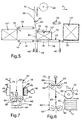
- the support table 24 is then rotated through 180 ° about the axis 26.
- the situation thus achieved is shown in FIG. 4.
- the first material section 76 runs on the seen in the conveying direction F. front side of the object located in the press channel 58 10 "over and the guide device 62 was again in its rest position 66 raised.
- the transfer channel 42 is on the support table 24 now ready for receiving the object 10 ".
- the one shown in FIG Situation corresponds to that of FIG. 1.
- the holding device 48 Since the objects 10, 10 ', 10' ', 10' '' during the rotation of the table 24 between the second belt conveyor 18 and the corresponding one Printing device 30, 32 must be kept pressed together the holding device 48 has no tensile force on the end section 78, but only this with free movement and fluttering while turning prevent. This enables the vacuum bars 46 to be connected continuously the vacuum source; the material web 70 can with low tensile force respective further conveying of the object 10, 10 ', 10' ', 10' '' from the Vacuum bar 46 are removed.
- the device a control device, not shown, for controlling all Drives of the device.
- the device shown is not only suitable for wrapping stacks of printed matter, but also of packages or individual newspapers, Magazines or the like. While printed matter in are usually compressible, these are other cuboid objects not necessarily. To avoid damage, the printing devices, for example, be provided with pressure sensors in order to prevent further lowering when a certain compressive force is achieved is.
- roller conveyors are also suitable. While the belt conveyors 14 and 20 are driven in the start-stop mode are the second belt conveyor 18 and the pressure belts 38 of the printing devices 30 and 32 driven by a reversible drive.
- each printing device is its own reversible belt conveyor or a corresponding conveyor assigned.
Landscapes
- Engineering & Computer Science (AREA)
- Mechanical Engineering (AREA)
- Packaging Of Special Articles (AREA)
- Basic Packing Technique (AREA)
Claims (10)
- Procédé d'enveloppement d'objets quadrangulaires avec un matériau d'enveloppement sous forme dé bande, comprenant un dispositif de transport (14) pour déplacer l'objet à envelopper (10) le long d'une voie de déplacement (22), un dispositif de guidage (62) pour le déroulement de la bande de matériau (70) d'un rouleau débiteur (68) et le guidage de cette bande de matériau (70) dans une direction (V) croisant la voie de déplacement (22), une table de support (24) disposée derrière la bande de matériau (70) s'étendant transversalement à la bande de déplacement (22), vue dans le sens d'avance (F) du dispositif de transport (14), pouvant tourner autour d'un axe (26) s'étendant à angle droit par rapport au sens d'avance (F), pour l'objet à envelopper (10), un dispositif de compression (30 ; 32) disposé au-dessus de la table de support (24), formant avec celle-ci un conduit de rabattement (42) pour la bande de matériau (70) et l'objet à envelopper (10), destiné à presser l'objet (10) pendant son enveloppement, le dispositif de guidage (62) étant prévu, après que la bande de matériau (70) a été placée autour de l'objet (10) au cours de son avance dans le conduit de rabattement (42), pour guider la bande de matériau (70) le long du côté arrière (82) de l'objet (10), vu dans la direction d'avancé (F), et pour créer ainsi, en formant une boucle de bande de matériau (80), à la fois d'une part un premier tronçon de bande de matériau (76) et d'autre part un deuxième tronçon de bande de matériau (90) s'étendant sur le côté arrière (82) de l'objet (10), dont la longueur est plus grande que la dimension de l'objet (10) dans la direction longitudinale de ce deuxième tronçon de bande de matériau (90), la partie terminale (78) de ce deuxième tronçon de bande de matériau (90) faisant saillie au-delà de l'objet (10), après la rotation de la table de support (24), étant rabattue lors du déplacement de l'objet (10) depuis la table de support (24) contre l'objet (10), caractérisé en ce que le dispositif de compression (30 ; 32) peut tourner conjointement avec la table de support (24) autour de l'axe (26) et en ce qu'il est prévu au moins deux dispositifs de compression (30, 32) espacés l'un de l'autre, commandés indépendamment l'un de l'autre à distance de la table de support (24) et pouvant tourner conjointement avec celle-ci autour de l'axe (26).
- Dispositif selon la revendication 1, caractérisé en ce que deux dispositifs de compression (30, 32) sont disposés symétriquement en face l'un de l'autre par rapport à un plan axial.
- Dispositif selon l'une quelconque des revendications 1 et 2, caractérisé en ce que la table de support (24) présente un transporteur à bande (18) qui est entraíné suivant un mouvement réversible.
- Dispositif selon l'une quelconque des revendications 1 à 3, caractérisé en ce que le dispositif de compression (30; 32), respectivement les dispositifs de compression (30, 32) présentent une bande de compression (38) sans fin, guidée autour du rouleau déflecteur (36), entraínée de préférence suivant un mouvement réversible.
- Dispositif selon l'une quelconque des revendications 1 à 4, caractérisé en ce que le dispositif de transport (14) présente, en aval par rapport à la bande de matériau (70) croisant la voie de déplacement (22), un transporteur à bande (16) de préférence entraíné en fonctionnement avec arrêt et démarrage automatiques, auquel est associé un autre dispositif de compression (50), afin de presser l'objet à envelopper (10) déjà avant son enveloppement avec la bande de matériau (70) et de l'introduire dans l'état comprimé dans le conduit de rabattement (42).
- Dispositif selon l'une quelconque des revendications 1 à 5, caractérisé par un dispositif de retenue (48) réalisé de préférence sous la forme d'une poutre à vide (46), disposé sous la table de support (24) et pouvant tourner conjointement avec celle-ci autour de l'axe (26), lequel est prévu pour retenir la partie terminale (78) du deuxième tronçon de bande de matériau (90) lors de la rotation de la table de support (24).
- Dispositif selon l'une quelconque des revendications 1 à 6, caractérisé en ce que le dispositif de guidage (62) présente des rouleaux déflecteurs (64) pour la bande de matériau (70), d'axes parallèles et déplaçables perpendiculairement au sens d'avance (F) ainsi qu'un dispositif de découpe (88) disposé entre eux pour découper la bande de matériau (70) en les premier et deuxième tronçons de bande de matériau (76 ; 90).
- Dispositif selon la revendication 7, caractérisé par un élément de support (86), qui est prévu pour serrer entre lui et les rouleaux déflecteurs (64), la bande de matériau (70) afin de découper celle-ci.
- Dispositif selon l'une quelconque des revendications 1 à 8, caractérisé par un autre dispositif de retenue (48') de préférence réalisé sous forme de poutre à vide (46), qui est prévu pour retenir le premier tronçon de bande de matériau (76).
- Procédé pour faire fonctionner un dispositif selon l'une quelconque des revendications 1 et 9, caractérisé en ce que le dispositif de compression (30, 32) des dispositifs de compression (30 ; 32) associés à la table de support (24), délivrant à chaque fois un objet (10, 10'), après la sortie de l'objet (10, 10') hors du conduit de rabattement (42) et avant qu'il n'ait atteint la position de rotation tournée vers la bande de matériau (70), est ajusté en fonction de la hauteur de l'autre dispositif de compression.
Applications Claiming Priority (2)
| Application Number | Priority Date | Filing Date | Title |
|---|---|---|---|
| CH138998 | 1998-06-30 | ||
| CH138998 | 1998-06-30 |
Publications (2)
| Publication Number | Publication Date |
|---|---|
| EP0968919A1 EP0968919A1 (fr) | 2000-01-05 |
| EP0968919B1 true EP0968919B1 (fr) | 2003-03-26 |
Family
ID=4209291
Family Applications (1)
| Application Number | Title | Priority Date | Filing Date |
|---|---|---|---|
| EP99111011A Expired - Lifetime EP0968919B1 (fr) | 1998-06-30 | 1999-06-10 | Procédé et dispositif d'enveloppement d'objets quadrangulaires avec un matériau d'emballage sous forme de bande |
Country Status (5)
| Country | Link |
|---|---|
| US (1) | US6223500B1 (fr) |
| EP (1) | EP0968919B1 (fr) |
| CA (1) | CA2275791C (fr) |
| DE (1) | DE59904691D1 (fr) |
| DK (1) | DK0968919T3 (fr) |
Families Citing this family (23)
| Publication number | Priority date | Publication date | Assignee | Title |
|---|---|---|---|---|
| DE10017562C1 (de) * | 2000-04-08 | 2001-09-06 | Continental Ag | Luftfeder mit zwei Endgliedern, zwischen denen ein Abstandssensor angeordnet ist |
| ES2260152T3 (es) * | 2000-12-20 | 2006-11-01 | Tissue Machinery Company S.P.A. | Procedimiento y aparato para el empaquetado de pilas de papel o similares con una lamina de embalaje. |
| DE10134257B4 (de) * | 2001-07-18 | 2007-04-26 | Cyklop Gmbh | Verpackungsmaschine |
| DE10134258B4 (de) * | 2001-07-18 | 2006-03-09 | Cyklop Gmbh | Verpackungsmaschine |
| US6761014B2 (en) * | 2002-08-16 | 2004-07-13 | Alain Cerf | Apparatus and process for wrapping articles on a conveyer |
| JP2008512321A (ja) * | 2004-09-13 | 2008-04-24 | ミードウエストベコ・コーポレーション | 封筒束および封筒束のパッケージの組立方法 |
| US7789226B2 (en) | 2004-09-13 | 2010-09-07 | Meadwestvaco Corporation | Packaged banded envelopes |
| US7360344B2 (en) * | 2004-09-17 | 2008-04-22 | Fpna Acquisition Corporation | Method and apparatus for sleeve or band-type packaging of a compressible article |
| EP1860033B1 (fr) * | 2006-05-26 | 2011-01-12 | MTC - Macchine Trasformazione Carta Srl | Dispositif d'envelopper une pile de feuilles |
| EP1860031B1 (fr) * | 2006-05-26 | 2009-10-28 | M T C - Macchine Trasformazione Carta S.r.l. | Dispositif d'alimentation de papier pour une machine à bander à produire des rouleaux de matériau en feuille |
| IT1393004B1 (it) * | 2009-02-13 | 2012-04-02 | Dolphin Pack S R L | Macchina confezionatrice concepita per la compressione e l'imballaggio di blocchi di materiale espanso |
| US20110197549A1 (en) * | 2010-02-15 | 2011-08-18 | Illinois Tool Works Inc. | Method and apparatus for compressing and holding in compression woven fabric articles |
| KR101184450B1 (ko) * | 2010-10-05 | 2012-09-20 | 삼성전자주식회사 | 자동포장장치 및 자동포장방법 |
| US9032869B2 (en) * | 2011-04-01 | 2015-05-19 | Systec Conveyors Inc. | Method for applying a strap around a load |
| US9505512B2 (en) | 2011-12-14 | 2016-11-29 | The Procter & Gamble Company | Sheet good loading device and method of loading sheet goods |
| JP5928139B2 (ja) * | 2012-05-08 | 2016-06-01 | ブラザー工業株式会社 | 包装装置 |
| ITBO20120619A1 (it) * | 2012-11-09 | 2014-05-10 | Tissue Machinery Co Spa | Apparato e metodo di confezionamento di pannolini o altri oggetti sanitari morbidi piatti ripiegati. |
| US9481481B2 (en) | 2012-11-15 | 2016-11-01 | Brother Kogyo Kabushiki Kaisha | Packaging device |
| JP5962450B2 (ja) | 2012-11-15 | 2016-08-03 | ブラザー工業株式会社 | 包装装置 |
| DE102021102034A1 (de) * | 2021-01-29 | 2022-08-04 | Focke & Co. (Gmbh & Co. Kg) | Verfahren und Vorrichtung zum Handhaben von (flachen) Gegenständen |
| US20260077890A1 (en) * | 2022-09-14 | 2026-03-19 | Signode Industrial Group Llc | System and method for forming a sleeve of paper wrapping material around a load |
| CN116573228B (zh) * | 2023-05-25 | 2025-07-29 | 广州长源包装设备有限公司 | 一种覆膜包装机及一种覆膜包装方法 |
| CN117842457A (zh) * | 2024-01-26 | 2024-04-09 | 嘉能工业智能设备(昆山)有限公司 | 牵引移动覆膜机构 |
Family Cites Families (8)
| Publication number | Priority date | Publication date | Assignee | Title |
|---|---|---|---|---|
| GB865077A (en) * | 1958-01-20 | 1961-04-12 | Sig Schweiz Industrieges | Improvements in or relating to packing machines |
| GB1094351A (en) * | 1964-06-04 | 1967-12-13 | Schmermund Alfred | Improvements in or relating to wrapping machines |
| US3469368A (en) * | 1967-07-20 | 1969-09-30 | Grace W R & Co | Wrapping machine |
| US3504476A (en) | 1967-07-20 | 1970-04-07 | Goodyear Tire & Rubber | Method of packaging |
| FR2409196A1 (fr) * | 1977-11-16 | 1979-06-15 | Starpak Pty Ltd | Procede et dispositif d'emballage |
| EP0120251B1 (fr) | 1983-03-22 | 1987-07-08 | Ferag AG | Procédé et dispositif d'enveloppement d'objets de préférence quadrangulaires avec un matériau d'emballage sous forme de bande |
| IT1245996B (it) | 1991-05-24 | 1994-11-07 | Wrapmatic Spa | Metodo per l'avvolgimento di risme di carta ed apparecchiatura che lo realizza. |
| DE19533086A1 (de) * | 1994-09-19 | 1996-03-21 | Ferag Ag | Verfahren und Vorrichtung zum Stapeln von flächigen Erzeugnissen, insbesondere Druckereiprodukten |
-
1999
- 1999-06-10 DE DE59904691T patent/DE59904691D1/de not_active Expired - Fee Related
- 1999-06-10 EP EP99111011A patent/EP0968919B1/fr not_active Expired - Lifetime
- 1999-06-10 DK DK99111011T patent/DK0968919T3/da active
- 1999-06-21 CA CA002275791A patent/CA2275791C/fr not_active Expired - Fee Related
- 1999-06-28 US US09/340,888 patent/US6223500B1/en not_active Expired - Fee Related
Also Published As
| Publication number | Publication date |
|---|---|
| DK0968919T3 (da) | 2003-04-22 |
| US6223500B1 (en) | 2001-05-01 |
| CA2275791A1 (fr) | 1999-12-30 |
| EP0968919A1 (fr) | 2000-01-05 |
| DE59904691D1 (de) | 2003-04-30 |
| CA2275791C (fr) | 2007-08-14 |
Similar Documents
| Publication | Publication Date | Title |
|---|---|---|
| EP0968919B1 (fr) | Procédé et dispositif d'enveloppement d'objets quadrangulaires avec un matériau d'emballage sous forme de bande | |
| EP0120251B1 (fr) | Procédé et dispositif d'enveloppement d'objets de préférence quadrangulaires avec un matériau d'emballage sous forme de bande | |
| DE69919493T2 (de) | Oberflächenwickler mit Klemmschneider | |
| DE60116994T2 (de) | Umwickelmaschine zum umwickeln von material auf eine hülse und entsprechendes wickelverfahren | |
| EP0894721B1 (fr) | Proçédé et dispositif pour cercler des objets unitaires ou des piles d'objets | |
| DE60113580T2 (de) | Schneidemaschine für eine Vielzahl von Küchen- und/oder Toiletten-Papierrollen | |
| DE69514112T2 (de) | Gummibandkette, verfahren und vorrichtung zu deren herstellung, sowie verfahren und vorrichtung für die zufuhr der gummibänder zu einer behandlungsvorrichtung | |
| DE69702274T2 (de) | Vorrichtung zum Sammeln und Stapeln von Schichtwerkstoffen, und ein Stapelverfahren | |
| DE3836214C2 (fr) | ||
| DE2729605A1 (de) | Vorrichtung zum aufeinanderfolgenden trennen abwechselnder schichten von einem einzigen stapel | |
| AT394021B (de) | Vorrichtung zum foerdern von gegenstaenden | |
| EP0890509A1 (fr) | Procédé et dispositif pour lier des objets unitaires ou des piles d'objets | |
| DE69301973T2 (de) | Vorrichtung zum Zuführen und Schneiden einer Folie zum Einwickeln von Gegenständen in einer Verpackungsmaschine | |
| DE4016484A1 (de) | Verpackungsvorrichtung fuer bahnrollen | |
| EP0313781A2 (fr) | Dispositif pour la fabrication de paquets portables tubulaires de produits d'imprimerie | |
| DE69708653T2 (de) | Quertrennvorrichtung für eine wickelmaschine | |
| DE3143436A1 (de) | Vorrichtung zum aufwickeln einer warenbahn | |
| DE1806918A1 (de) | Verfahren und Vorrichtung zur Herstellung von Beuteln | |
| EP0100462A2 (fr) | Dispositif d'enroulement pour bandes | |
| DE2529126B2 (de) | Vorrichtung für die Zuführung von Schußfäden zu einer Kettenwirkmaschine | |
| DE69506060T2 (de) | Vorrichtung zum Schneiden und klebstofflosen Anbringen des Bahnanfangs für eine neue Wickelrolle auf den Wickelkern eines Wicklers | |
| EP0849179B1 (fr) | Dispositif pour emballer un rouleau de matériau en bande avec une bande d'emballage | |
| DE60124366T2 (de) | Umfangsangetriebene Wickelmaschine und Verfahren zur Produktion von Rollen aus Bahnmaterial | |
| EP0873940B1 (fr) | Machine de coupe de rouleaux avec dispositif d'emballage | |
| DE19817870B4 (de) | Wickelvorrichtung für eine Bahn |
Legal Events
| Date | Code | Title | Description |
|---|---|---|---|
| PUAI | Public reference made under article 153(3) epc to a published international application that has entered the european phase |
Free format text: ORIGINAL CODE: 0009012 |
|
| AK | Designated contracting states |
Kind code of ref document: A1 Designated state(s): CH DE DK GB IT LI NL SE |
|
| AX | Request for extension of the european patent |
Free format text: AL;LT;LV;MK;RO;SI |
|
| 17P | Request for examination filed |
Effective date: 20000119 |
|
| AKX | Designation fees paid |
Free format text: CH DE DK GB IT LI NL SE |
|
| 17Q | First examination report despatched |
Effective date: 20010621 |
|
| GRAH | Despatch of communication of intention to grant a patent |
Free format text: ORIGINAL CODE: EPIDOS IGRA |
|
| GRAH | Despatch of communication of intention to grant a patent |
Free format text: ORIGINAL CODE: EPIDOS IGRA |
|
| GRAA | (expected) grant |
Free format text: ORIGINAL CODE: 0009210 |
|
| AK | Designated contracting states |
Designated state(s): CH DE DK GB IT LI NL SE |
|
| REG | Reference to a national code |
Ref country code: GB Ref legal event code: FG4D Free format text: NOT ENGLISH |
|
| REG | Reference to a national code |
Ref country code: CH Ref legal event code: EP |
|
| REG | Reference to a national code |
Ref country code: CH Ref legal event code: NV Representative=s name: PATENTANWAELTE SCHAAD, BALASS, MENZL & PARTNER AG |
|
| GBT | Gb: translation of ep patent filed (gb section 77(6)(a)/1977) |
Effective date: 20030326 |
|
| REG | Reference to a national code |
Ref country code: DK Ref legal event code: T3 |
|
| REF | Corresponds to: |
Ref document number: 59904691 Country of ref document: DE Date of ref document: 20030430 Kind code of ref document: P |
|
| REG | Reference to a national code |
Ref country code: SE Ref legal event code: TRGR |
|
| PLBE | No opposition filed within time limit |
Free format text: ORIGINAL CODE: 0009261 |
|
| STAA | Information on the status of an ep patent application or granted ep patent |
Free format text: STATUS: NO OPPOSITION FILED WITHIN TIME LIMIT |
|
| 26N | No opposition filed |
Effective date: 20031230 |
|
| REG | Reference to a national code |
Ref country code: CH Ref legal event code: PFA Owner name: FERAG AG Free format text: FERAG AG#ZUERICHSTRASSE 74#8340 HINWIL (CH) -TRANSFER TO- FERAG AG#PATENTABTEILUNG Z. H. MARKUS FELIX ZUERICHSTRASSE 74#8340 HINWIL (CH) |
|
| PGFP | Annual fee paid to national office [announced via postgrant information from national office to epo] |
Ref country code: DK Payment date: 20080610 Year of fee payment: 10 Ref country code: CH Payment date: 20080625 Year of fee payment: 10 |
|
| PGFP | Annual fee paid to national office [announced via postgrant information from national office to epo] |
Ref country code: IT Payment date: 20080624 Year of fee payment: 10 |
|
| PGFP | Annual fee paid to national office [announced via postgrant information from national office to epo] |
Ref country code: SE Payment date: 20080612 Year of fee payment: 10 Ref country code: NL Payment date: 20080618 Year of fee payment: 10 Ref country code: DE Payment date: 20080620 Year of fee payment: 10 |
|
| PGFP | Annual fee paid to national office [announced via postgrant information from national office to epo] |
Ref country code: GB Payment date: 20080620 Year of fee payment: 10 |
|
| REG | Reference to a national code |
Ref country code: CH Ref legal event code: PL |
|
| REG | Reference to a national code |
Ref country code: DK Ref legal event code: EBP |
|
| GBPC | Gb: european patent ceased through non-payment of renewal fee |
Effective date: 20090610 |
|
| NLV4 | Nl: lapsed or anulled due to non-payment of the annual fee |
Effective date: 20100101 |
|
| PG25 | Lapsed in a contracting state [announced via postgrant information from national office to epo] |
Ref country code: LI Free format text: LAPSE BECAUSE OF NON-PAYMENT OF DUE FEES Effective date: 20090630 Ref country code: CH Free format text: LAPSE BECAUSE OF NON-PAYMENT OF DUE FEES Effective date: 20090630 |
|
| PG25 | Lapsed in a contracting state [announced via postgrant information from national office to epo] |
Ref country code: GB Free format text: LAPSE BECAUSE OF NON-PAYMENT OF DUE FEES Effective date: 20090610 |
|
| PG25 | Lapsed in a contracting state [announced via postgrant information from national office to epo] |
Ref country code: DE Free format text: LAPSE BECAUSE OF NON-PAYMENT OF DUE FEES Effective date: 20100101 |
|
| PG25 | Lapsed in a contracting state [announced via postgrant information from national office to epo] |
Ref country code: NL Free format text: LAPSE BECAUSE OF NON-PAYMENT OF DUE FEES Effective date: 20100101 Ref country code: DK Free format text: LAPSE BECAUSE OF NON-PAYMENT OF DUE FEES Effective date: 20090630 |
|
| PG25 | Lapsed in a contracting state [announced via postgrant information from national office to epo] |
Ref country code: IT Free format text: LAPSE BECAUSE OF NON-PAYMENT OF DUE FEES Effective date: 20090610 |
|
| PG25 | Lapsed in a contracting state [announced via postgrant information from national office to epo] |
Ref country code: SE Free format text: LAPSE BECAUSE OF NON-PAYMENT OF DUE FEES Effective date: 20090611 |