EP0968938B1 - Etagère inclinée pour la préparation de commandes à partir des unités de stockage - Google Patents
Etagère inclinée pour la préparation de commandes à partir des unités de stockage Download PDFInfo
- Publication number
- EP0968938B1 EP0968938B1 EP99109580A EP99109580A EP0968938B1 EP 0968938 B1 EP0968938 B1 EP 0968938B1 EP 99109580 A EP99109580 A EP 99109580A EP 99109580 A EP99109580 A EP 99109580A EP 0968938 B1 EP0968938 B1 EP 0968938B1
- Authority
- EP
- European Patent Office
- Prior art keywords
- return stop
- track
- fact
- pivoted
- another
- Prior art date
- Legal status (The legal status is an assumption and is not a legal conclusion. Google has not performed a legal analysis and makes no representation as to the accuracy of the status listed.)
- Expired - Lifetime
Links
Images

Classifications
-
- B—PERFORMING OPERATIONS; TRANSPORTING
- B65—CONVEYING; PACKING; STORING; HANDLING THIN OR FILAMENTARY MATERIAL
- B65G—TRANSPORT OR STORAGE DEVICES, e.g. CONVEYORS FOR LOADING OR TIPPING, SHOP CONVEYOR SYSTEMS OR PNEUMATIC TUBE CONVEYORS
- B65G1/00—Storing articles, individually or in orderly arrangement, in warehouses or magazines
- B65G1/02—Storage devices
- B65G1/04—Storage devices mechanical
- B65G1/06—Storage devices mechanical with means for presenting articles for removal at predetermined position or level
- B65G1/08—Storage devices mechanical with means for presenting articles for removal at predetermined position or level the articles being fed by gravity
Definitions
- the invention relates to a flow rack for picking storage units, especially at a changing place, preferably in several levels one above the other and inclined towards the picking side, at a distance parallel running tracks on which the bearing units under the influence of gravity from the loading side directly into a removal position arrive, and at least one direction-dependent assigned to the raceways, pivotable in opposite directions about a fixed axis of rotation Pass lock, through which the storage unit in one of the Entnhameposition upstream position can be determined, the Pass lock as an integral part of the career in its cross section is arranged substantially U-shaped track bar and from a Swivel link segment and a backstop, which has a Coupling member are interconnected.
- Flow rack is known from DE-A-3037634.
- a flow rack made known by DE 297 117 10 U1
- a storage unit e.g. a container or box
- a flow rack made known by DE 297 117 10 U1
- the two complementary raceways designed as roller or roller tracks to provide an automatic lock. This is with the side of the track vertical axis of rotation and is articulated by a fixed axis of rotation pivotable angle formed by means of at least one spring in a Basic position is held, from which he in opposite directions is pivotable against the force of the spring.
- the spring-loaded lock allows a storage unit to be moved from the loading side directly into the Withdrawal position, and after picking will move back prevented or pushed into the removal position beyond the position of the lock, because the lock snaps back after passing through the storage unit and clamps an edge of the bearing unit of the legs of the angle lock.
- this is one Position-limiting, additional stop required, which is also spring-operated is.
- the problem here is that in the case of deterioration due to frequent use Spring force the locking and position positioning can no longer be guaranteed can; other than that, these angle locks require additional space each on the outside of the raceways.
- the invention is based, with a flow rack the task at the beginning mentioned type to make the anti-trap barrier easier and more reliable.
- the coupling member as a wire bracket is formed, which with angled at its free end, each other facing webs are engaged on both sides in the backstop and with its closed temple end in a curved slot of the Swivel link segment is guided.
- a preferred embodiment of the invention provides that the pivot gate segment and the backstop each above their center of gravity axles inserted freely through the side walls of the track strips and protrude above the track level in the unloaded state.
- the high bearing point makes it possible for the two elements of the flow barrier on the one hand in the unloaded state over the Project upwards at the level of the career track and only after one load automatically swing back into this starting position by their weight.
- the backstop with one in the unloaded state is formed on the ledge base supporting stop edge that holds Weight of the adjacent bearing unit the backstop safely in this Locked position, because swiveling is due to the stop contact the inguinal floor not possible.
- the swivel link segment automatically in its starting position.
- pivot link segment and the backstop have a substantially U-shaped cross section. These locking elements can be easily cut from a sheet metal blank or alternatively manufacture as a plastic element or the like.
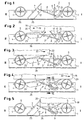
- the track 1 consists of a U-shaped strip profile 3 (see FIG. 6) and is with numerous rollers 4 equipped, the upper edges of which define the career level 5.
- the Pass barrier 2 is an integral part of the track 1 in the cavity the track 3 is arranged and consists of a pivot link segment 6 and a backstop 7, both of which have a U-shaped cross section and via a coupling member designed as a wire bracket 8 (see also FIG. 9) are connected to each other depending on the movement, but on the other hand in certain operating conditions only a swivel movement of only Backstop 7 or only the pivot link segment 6 allowed.
- the wire bracket 8 engages in one with its closed end curved slot 9 of the pivot link segment 6, which accordingly its design a free run of the wire bracket 8 when swiveling the Backstop 7 allows without the pivot link segment 6 in its position is changed or pivoted.
- the wire bracket 8 has angled, facing each other at its free end Crosspieces 10a, 10b (see FIGS. 6 and 9), which are used to connect the Backstop element 7 from the outside thereof in receiving bores 11 (cf. in Figure 8 the blank 12) are engaged.
- Both the pivot link segment 6 and the backstop 7 are clearly above their center of gravity through the side walls 13 of the track strips 3 and through holes 14 of the Backstop 7 or through holes 15 (see FIG. 7 the blank 16 and the side view there) of the pivot link segment 6 Axes 17 (see FIG. 6) on which they are freely movable.
- the Swivel link segment 6 and the backstop 7 - if they are out Sheet metal consist of the sheet metal blanks 16 and 12 shown in FIGS. 7 and 8 in a simple manner by folding around the sheet metal blanks 12 or 16 dashed fold lines produced; after their completion they have an in essential U-shaped cross section.
Landscapes
- Engineering & Computer Science (AREA)
- Mechanical Engineering (AREA)
- Warehouses Or Storage Devices (AREA)
Claims (4)
- Casier de stockage dynamique pour la préparation de commandes d'unités de stockage (18), en particulier à un emplacement de changement, comportant de préférence des bandes circulantes (1) superposées en plusieurs plans, inclinées vers le côté de la préparation de commandes et écartées parallèlement les unes des autres, sur lesquelles les unités de stockage (18) arrivent, sous l'influence de la force de gravité, à partir du côté de chargement (I) directement en position de prélèvement (II) et comportant au moins un barrage dynamique (2) associé aux bandes circulantes (1) et dépendant de la direction pouvant pivoter autour d'un axe de rotation à emplacement fixe (17) dans des directions opposées, grâce auquel une unité de stockage (18) peut être fixée dans une position en amont de la position de prélèvement dans le sens du mouvement, le barrage dynamique (2) étant installé comme partie intégrante de la bande circulante (1) dans le couloir (3) de bande circulante globalement en forme de U dans sa section transversale et consistant en un segment à coulisse pivotant (6) ainsi qu'en un élément de barrage de marche arrière (7), qui sont reliés l'un à l'autre par l'intermédiaire d'un élément d'accouplement (8),
caractérisé en ce que
l'élément d'accouplement est configuré comme une bride en fil de fer (8) qui s'enclenche des deux côtés dans l'élément de barrage de marche arrière (7) grâce à des traverses (10a, 10b) coudées à son extrémité libre et tournées l'une vers l'autre et est guidée avec son extrémité de bride fermée dans une fente de forme courbe (9) du segment à coulisse pivotant (7). - Casier de stockage dynamique selon la revendication 1,
caractérisé en ce que
le segment à coulisse pivotant (6) et l'élément de barrage de marche arrière (7) sont installés respectivement de manière à pouvoir bouger librement au dessus de leur centre de gravité sur les axes (7) plantés à travers les parois latérales (13) des couloirs de bande circulante (3) et dépassent au dessus du plan de la bande circulante (5) quand elle n'est pas chargée. - Casier de stockage dynamique selon la revendication 1 ou 2,
caractérisé en ce que
le segment à coulisse pivotant (6) et l'élément de barrage de marche arrière (7) possèdent une section transversale globalement en forme de U. - Casier de stockage dynamique selon une des revendications 1 à 3,
caractérisé en ce que
l'élément de barrage de marche arrière (7) est configuré avec un rebord de butée (25) s'appuyant sur le fond du couloir (26).
Applications Claiming Priority (2)
| Application Number | Priority Date | Filing Date | Title |
|---|---|---|---|
| DE19829258 | 1998-07-01 | ||
| DE19829258A DE19829258A1 (de) | 1998-07-01 | 1998-07-01 | Durchlaufregal zum Kommissionieren von Lagereinheiten |
Publications (2)
| Publication Number | Publication Date |
|---|---|
| EP0968938A1 EP0968938A1 (fr) | 2000-01-05 |
| EP0968938B1 true EP0968938B1 (fr) | 2002-12-11 |
Family
ID=7872549
Family Applications (1)
| Application Number | Title | Priority Date | Filing Date |
|---|---|---|---|
| EP99109580A Expired - Lifetime EP0968938B1 (fr) | 1998-07-01 | 1999-05-14 | Etagère inclinée pour la préparation de commandes à partir des unités de stockage |
Country Status (3)
| Country | Link |
|---|---|
| EP (1) | EP0968938B1 (fr) |
| DE (2) | DE19829258A1 (fr) |
| ES (1) | ES2189312T3 (fr) |
Cited By (5)
| Publication number | Priority date | Publication date | Assignee | Title |
|---|---|---|---|---|
| EP2354046A1 (fr) | 2010-01-29 | 2011-08-10 | BITO-Lagertechnik Bittmann GmbH | Etagère à couloir de roulement dotée d'un dispositif de séparation |
| DE102011078600B3 (de) * | 2011-07-04 | 2012-12-20 | Bito-Lagertechnik Bittmann Gmbh | Durchlaufregal mit Steuerfahne |
| EP2543613A1 (fr) | 2011-07-04 | 2013-01-09 | BITO-Lagertechnik Bittmann GmbH | Étagère traversante dotée d'un dispositif de séparation mécanique lâche |
| DE102011078602A1 (de) | 2011-07-04 | 2013-01-10 | Bito-Lagertechnik Bittmann Gmbh | Durchlaufregal mit Schnappriegelverschluss |
| US11565891B2 (en) | 2018-08-21 | 2023-01-31 | Euroroll GmbH | Actuating apparatus for actuating a separating device for a gravitational conveyor |
Families Citing this family (6)
| Publication number | Priority date | Publication date | Assignee | Title |
|---|---|---|---|---|
| DE10021318A1 (de) * | 2000-05-02 | 2001-11-15 | Erhard Schmale | Durchlaufregal zum Kommissionieren von Lagereinheiten |
| DE20020595U1 (de) * | 2000-12-05 | 2001-03-08 | Nedcon Magazijninrichting B.V., Doetinchem | Durchlaufregal für Kommissionierzwecke |
| AT511141A1 (de) * | 2011-02-03 | 2012-09-15 | Tgw Logistics Group Gmbh | Verfahren und anlage zum kommissionieren von artikeln |
| ES2525379T3 (es) * | 2011-03-30 | 2014-12-23 | Interroll Holding Ag | Módulo transportador de rodillos |
| DE102012212145B4 (de) * | 2012-07-11 | 2018-11-08 | Bito-Lagertechnik Bittmann Gmbh | Separiervorrichtung |
| DE102016211806B4 (de) * | 2016-06-30 | 2022-03-03 | Bito-Lagertechnik Bittmann Gmbh | Durchlaufregal zum Kommissionieren von Lagereinheiten |
Family Cites Families (3)
| Publication number | Priority date | Publication date | Assignee | Title |
|---|---|---|---|---|
| DE3037634A1 (de) * | 1976-03-31 | 1982-05-19 | Walter Dr.-Ing. 5100 Aachen Jürgens | Ragal |
| DE3716503A1 (de) * | 1987-05-16 | 1988-11-24 | Schaefer Gmbh Fritz | Durchlaufregal fuer mit waren beladene behaelter, z. b. kaesten |
| DE29711710U1 (de) | 1997-07-04 | 1997-09-11 | Nedcon Magazijninrichting B.V., Doetinchem | Durchlaufregal zum Kommissionieren |
-
1998
- 1998-07-01 DE DE19829258A patent/DE19829258A1/de not_active Withdrawn
-
1999
- 1999-05-14 DE DE59903716T patent/DE59903716D1/de not_active Expired - Lifetime
- 1999-05-14 EP EP99109580A patent/EP0968938B1/fr not_active Expired - Lifetime
- 1999-05-14 ES ES99109580T patent/ES2189312T3/es not_active Expired - Lifetime
Cited By (10)
| Publication number | Priority date | Publication date | Assignee | Title |
|---|---|---|---|---|
| EP2354046A1 (fr) | 2010-01-29 | 2011-08-10 | BITO-Lagertechnik Bittmann GmbH | Etagère à couloir de roulement dotée d'un dispositif de séparation |
| DE102010001356B3 (de) * | 2010-01-29 | 2012-10-25 | Bito-Lagertechnik Bittmann Gmbh | Durchlaufregal mit Separiervorrichtung |
| DE102011078600B3 (de) * | 2011-07-04 | 2012-12-20 | Bito-Lagertechnik Bittmann Gmbh | Durchlaufregal mit Steuerfahne |
| EP2543613A1 (fr) | 2011-07-04 | 2013-01-09 | BITO-Lagertechnik Bittmann GmbH | Étagère traversante dotée d'un dispositif de séparation mécanique lâche |
| EP2543614A1 (fr) | 2011-07-04 | 2013-01-09 | BITO-Lagertechnik Bittmann GmbH | Etagère traversante dotée d'un fanion de commande |
| DE102011078602A1 (de) | 2011-07-04 | 2013-01-10 | Bito-Lagertechnik Bittmann Gmbh | Durchlaufregal mit Schnappriegelverschluss |
| DE102011078598A1 (de) | 2011-07-04 | 2013-01-10 | Bito-Lagertechnik Bittmann Gmbh | Durchlaufregal mit mechanisch lose gekoppelter Separiervorrichtung |
| DE102011078602B4 (de) * | 2011-07-04 | 2013-02-21 | Bito-Lagertechnik Bittmann Gmbh | Durchlaufregal mit Schnappriegelverschluss |
| DE102011078598B4 (de) * | 2011-07-04 | 2013-09-19 | Bito-Lagertechnik Bittmann Gmbh | Ein Regalsystem mit einem Durchlaufregal und mit mechanisch lose gekoppelter Separiervorrichtung |
| US11565891B2 (en) | 2018-08-21 | 2023-01-31 | Euroroll GmbH | Actuating apparatus for actuating a separating device for a gravitational conveyor |
Also Published As
| Publication number | Publication date |
|---|---|
| ES2189312T3 (es) | 2003-07-01 |
| EP0968938A1 (fr) | 2000-01-05 |
| DE19829258A1 (de) | 2000-01-05 |
| DE59903716D1 (de) | 2003-01-23 |
Similar Documents
| Publication | Publication Date | Title |
|---|---|---|
| DE1296088B (de) | Rollenbahn mit einem Rollenstuetzglied | |
| DE102016113180A1 (de) | Vorrichtung zum Fördern und Sortieren von Stückgütern und Verfahren zum Sortieren von Stückgütern | |
| DE6903037U (de) | Abstellgeruest mit umlaufplattformen fuer fahrzeuge. | |
| EP0968938A1 (fr) | Etagère inclinée pour la préparation de commandes à partir des unités de stockage | |
| EP0888983B1 (fr) | Couloir de roulement pour la préparation de commandes | |
| DE1659963A1 (de) | Klappbare Wand | |
| DE3411701C2 (de) | Schwerkraft-Fördereinrichtung für mit Rädern versehene Paletten | |
| DE4007707A1 (de) | Rollenbahn fuer skids | |
| DE10020909B4 (de) | Vorrichtung zur Förderung einer Vorratsrolle | |
| CH676457A5 (fr) | ||
| DE2945213A1 (de) | Foerderbahn mit eingabe- und abwerfvorrichtungen | |
| DE3336190C2 (de) | Stauketten-Fördereinrichtung für hängende Stückgüter | |
| EP3263493A1 (fr) | Rayonnage de préparation de commande d'unités de stockage | |
| DE20105582U1 (de) | Lagerlift | |
| DE2352424A1 (de) | Foerderer zum transport von zeitungsstoessen bzw. -paketen | |
| DE3006941C2 (de) | Ablaufrost für den geräuscharmen Quertransport von Rundmaterial | |
| DE1944345C3 (de) | Schleppkettenkreisförderer | |
| DE2601000C3 (de) | Durchlaufkanal für Kommissionier-Durchlauflager | |
| DE3219872C2 (de) | Vorrichtung zum geräuscharmen Ablegen von Stangenprofilen, insbesondere runden Stäben und Rohren | |
| DE20002242U1 (de) | Fördereinrichtung mit mehreren Ebenen | |
| DE2305928B2 (de) | Stativ | |
| DE3618755A1 (de) | Vorrichtung zum transport von platten zwischen einer hauptstrecke und einer an diese angesetzte abzweigungseinheit | |
| DE20006862U1 (de) | Begehbare Plattformanordnung | |
| DE2729593C2 (de) | Fördervorrichtung | |
| DE3926472C1 (fr) |
Legal Events
| Date | Code | Title | Description |
|---|---|---|---|
| PUAI | Public reference made under article 153(3) epc to a published international application that has entered the european phase |
Free format text: ORIGINAL CODE: 0009012 |
|
| AK | Designated contracting states |
Kind code of ref document: A1 Designated state(s): DE ES FR GB NL |
|
| AX | Request for extension of the european patent |
Free format text: AL;LT;LV;MK;RO;SI |
|
| 17P | Request for examination filed |
Effective date: 20000316 |
|
| AKX | Designation fees paid |
Free format text: DE ES FR GB NL |
|
| 17Q | First examination report despatched |
Effective date: 20010628 |
|
| GRAG | Despatch of communication of intention to grant |
Free format text: ORIGINAL CODE: EPIDOS AGRA |
|
| GRAG | Despatch of communication of intention to grant |
Free format text: ORIGINAL CODE: EPIDOS AGRA |
|
| GRAH | Despatch of communication of intention to grant a patent |
Free format text: ORIGINAL CODE: EPIDOS IGRA |
|
| GRAH | Despatch of communication of intention to grant a patent |
Free format text: ORIGINAL CODE: EPIDOS IGRA |
|
| GRAA | (expected) grant |
Free format text: ORIGINAL CODE: 0009210 |
|
| AK | Designated contracting states |
Kind code of ref document: B1 Designated state(s): DE ES FR GB NL |
|
| REG | Reference to a national code |
Ref country code: GB Ref legal event code: FG4D Free format text: NOT ENGLISH |
|
| REF | Corresponds to: |
Ref document number: 59903716 Country of ref document: DE Date of ref document: 20030123 |
|
| GBT | Gb: translation of ep patent filed (gb section 77(6)(a)/1977) |
Effective date: 20030415 |
|
| REG | Reference to a national code |
Ref country code: ES Ref legal event code: FG2A Ref document number: 2189312 Country of ref document: ES Kind code of ref document: T3 |
|
| ET | Fr: translation filed | ||
| PLBE | No opposition filed within time limit |
Free format text: ORIGINAL CODE: 0009261 |
|
| 26N | No opposition filed |
Effective date: 20030912 |
|
| PGFP | Annual fee paid to national office [announced via postgrant information from national office to epo] |
Ref country code: GB Payment date: 20140521 Year of fee payment: 16 |
|
| PGFP | Annual fee paid to national office [announced via postgrant information from national office to epo] |
Ref country code: DE Payment date: 20140521 Year of fee payment: 16 Ref country code: FR Payment date: 20140527 Year of fee payment: 16 Ref country code: NL Payment date: 20140521 Year of fee payment: 16 Ref country code: ES Payment date: 20140528 Year of fee payment: 16 |
|
| REG | Reference to a national code |
Ref country code: DE Ref legal event code: R119 Ref document number: 59903716 Country of ref document: DE |
|
| GBPC | Gb: european patent ceased through non-payment of renewal fee |
Effective date: 20150514 |
|
| REG | Reference to a national code |
Ref country code: NL Ref legal event code: MM Effective date: 20150601 |
|
| REG | Reference to a national code |
Ref country code: FR Ref legal event code: ST Effective date: 20160129 |
|
| PG25 | Lapsed in a contracting state [announced via postgrant information from national office to epo] |
Ref country code: DE Free format text: LAPSE BECAUSE OF NON-PAYMENT OF DUE FEES Effective date: 20151201 Ref country code: NL Free format text: LAPSE BECAUSE OF NON-PAYMENT OF DUE FEES Effective date: 20150601 Ref country code: GB Free format text: LAPSE BECAUSE OF NON-PAYMENT OF DUE FEES Effective date: 20150514 |
|
| PG25 | Lapsed in a contracting state [announced via postgrant information from national office to epo] |
Ref country code: FR Free format text: LAPSE BECAUSE OF NON-PAYMENT OF DUE FEES Effective date: 20150601 |
|
| REG | Reference to a national code |
Ref country code: ES Ref legal event code: FD2A Effective date: 20170202 |
|
| PG25 | Lapsed in a contracting state [announced via postgrant information from national office to epo] |
Ref country code: ES Free format text: LAPSE BECAUSE OF NON-PAYMENT OF DUE FEES Effective date: 20150515 |