EP0968972A1 - Verfahren zum Herstellen einer optischen Faser - Google Patents
Verfahren zum Herstellen einer optischen Faser Download PDFInfo
- Publication number
- EP0968972A1 EP0968972A1 EP99305104A EP99305104A EP0968972A1 EP 0968972 A1 EP0968972 A1 EP 0968972A1 EP 99305104 A EP99305104 A EP 99305104A EP 99305104 A EP99305104 A EP 99305104A EP 0968972 A1 EP0968972 A1 EP 0968972A1
- Authority
- EP
- European Patent Office
- Prior art keywords
- sulfur
- tube
- treatment
- chlorides
- halides
- Prior art date
- Legal status (The legal status is an assumption and is not a legal conclusion. Google has not performed a legal analysis and makes no representation as to the accuracy of the status listed.)
- Granted
Links
- 239000013307 optical fiber Substances 0.000 title claims abstract description 12
- 238000000034 method Methods 0.000 title claims description 36
- 230000008569 process Effects 0.000 title claims description 30
- VYPSYNLAJGMNEJ-UHFFFAOYSA-N Silicium dioxide Chemical compound O=[Si]=O VYPSYNLAJGMNEJ-UHFFFAOYSA-N 0.000 claims abstract description 85
- 239000002245 particle Substances 0.000 claims abstract description 74
- 238000011282 treatment Methods 0.000 claims abstract description 61
- FWMUJAIKEJWSSY-UHFFFAOYSA-N sulfur dichloride Chemical class ClSCl FWMUJAIKEJWSSY-UHFFFAOYSA-N 0.000 claims abstract description 49
- 239000011593 sulfur Substances 0.000 claims abstract description 42
- 229910052717 sulfur Inorganic materials 0.000 claims abstract description 42
- 239000000377 silicon dioxide Substances 0.000 claims abstract description 37
- -1 sulfur halides Chemical class 0.000 claims abstract description 31
- 239000008246 gaseous mixture Substances 0.000 claims abstract description 14
- 239000000835 fiber Substances 0.000 claims abstract description 12
- 229910044991 metal oxide Inorganic materials 0.000 claims abstract description 11
- 150000004706 metal oxides Chemical class 0.000 claims abstract description 11
- 239000000758 substrate Substances 0.000 claims abstract description 10
- 150000004820 halides Chemical class 0.000 claims abstract description 8
- 238000005245 sintering Methods 0.000 claims abstract 3
- PXJJSXABGXMUSU-UHFFFAOYSA-N disulfur dichloride Chemical compound ClSSCl PXJJSXABGXMUSU-UHFFFAOYSA-N 0.000 claims description 101
- 239000000460 chlorine Substances 0.000 claims description 47
- ZAMOUSCENKQFHK-UHFFFAOYSA-N Chlorine atom Chemical compound [Cl] ZAMOUSCENKQFHK-UHFFFAOYSA-N 0.000 claims description 43
- 229910052801 chlorine Inorganic materials 0.000 claims description 43
- MCMNRKCIXSYSNV-UHFFFAOYSA-N Zirconium dioxide Chemical compound O=[Zr]=O MCMNRKCIXSYSNV-UHFFFAOYSA-N 0.000 claims description 30
- NINIDFKCEFEMDL-UHFFFAOYSA-N Sulfur Chemical compound [S] NINIDFKCEFEMDL-UHFFFAOYSA-N 0.000 claims description 24
- 238000006243 chemical reaction Methods 0.000 claims description 22
- 239000007789 gas Substances 0.000 claims description 22
- QDOXWKRWXJOMAK-UHFFFAOYSA-N dichromium trioxide Chemical compound O=[Cr]O[Cr]=O QDOXWKRWXJOMAK-UHFFFAOYSA-N 0.000 claims description 20
- QVGXLLKOCUKJST-UHFFFAOYSA-N atomic oxygen Chemical compound [O] QVGXLLKOCUKJST-UHFFFAOYSA-N 0.000 claims description 17
- 239000001301 oxygen Substances 0.000 claims description 17
- 229910052760 oxygen Inorganic materials 0.000 claims description 17
- IJGRMHOSHXDMSA-UHFFFAOYSA-N Atomic nitrogen Chemical compound N#N IJGRMHOSHXDMSA-UHFFFAOYSA-N 0.000 claims description 12
- XLYOFNOQVPJJNP-UHFFFAOYSA-N water Substances O XLYOFNOQVPJJNP-UHFFFAOYSA-N 0.000 claims description 11
- 238000004519 manufacturing process Methods 0.000 claims description 9
- 239000003870 refractory metal Substances 0.000 claims description 8
- 239000003570 air Substances 0.000 claims description 6
- 229910052757 nitrogen Inorganic materials 0.000 claims description 6
- 238000003980 solgel method Methods 0.000 claims description 5
- XKRFYHLGVUSROY-UHFFFAOYSA-N Argon Chemical compound [Ar] XKRFYHLGVUSROY-UHFFFAOYSA-N 0.000 claims description 4
- 125000002887 hydroxy group Chemical group [H]O* 0.000 claims description 3
- 229910052786 argon Inorganic materials 0.000 claims description 2
- 239000001307 helium Substances 0.000 claims description 2
- 229910052734 helium Inorganic materials 0.000 claims description 2
- SWQJXJOGLNCZEY-UHFFFAOYSA-N helium atom Chemical compound [He] SWQJXJOGLNCZEY-UHFFFAOYSA-N 0.000 claims description 2
- 229910052754 neon Inorganic materials 0.000 claims description 2
- GKAOGPIIYCISHV-UHFFFAOYSA-N neon atom Chemical compound [Ne] GKAOGPIIYCISHV-UHFFFAOYSA-N 0.000 claims description 2
- 150000001805 chlorine compounds Chemical class 0.000 claims 6
- 239000005864 Sulphur Substances 0.000 claims 1
- FYSNRJHAOHDILO-UHFFFAOYSA-N thionyl chloride Chemical compound ClS(Cl)=O FYSNRJHAOHDILO-UHFFFAOYSA-N 0.000 abstract description 35
- 230000009467 reduction Effects 0.000 abstract description 6
- 230000001747 exhibiting effect Effects 0.000 abstract 1
- 230000000977 initiatory effect Effects 0.000 abstract 1
- KZBUYRJDOAKODT-UHFFFAOYSA-N Chlorine Chemical compound ClCl KZBUYRJDOAKODT-UHFFFAOYSA-N 0.000 description 33
- 239000000499 gel Substances 0.000 description 32
- 238000005530 etching Methods 0.000 description 23
- 239000003153 chemical reaction reagent Substances 0.000 description 19
- 238000005906 dihydroxylation reaction Methods 0.000 description 14
- 150000001875 compounds Chemical class 0.000 description 12
- 239000000203 mixture Substances 0.000 description 10
- 238000005253 cladding Methods 0.000 description 8
- 238000009792 diffusion process Methods 0.000 description 8
- 238000010438 heat treatment Methods 0.000 description 8
- 239000008188 pellet Substances 0.000 description 8
- 229910006124 SOCl2 Inorganic materials 0.000 description 7
- 230000035484 reaction time Effects 0.000 description 6
- 239000011162 core material Substances 0.000 description 5
- 230000000694 effects Effects 0.000 description 5
- 238000011065 in-situ storage Methods 0.000 description 5
- 238000012545 processing Methods 0.000 description 5
- YCKRFDGAMUMZLT-UHFFFAOYSA-N Fluorine atom Chemical compound [F] YCKRFDGAMUMZLT-UHFFFAOYSA-N 0.000 description 4
- YAABVRPJBUVYMX-UHFFFAOYSA-N [S].ClF Chemical class [S].ClF YAABVRPJBUVYMX-UHFFFAOYSA-N 0.000 description 4
- 230000015572 biosynthetic process Effects 0.000 description 4
- 238000000151 deposition Methods 0.000 description 4
- 230000008021 deposition Effects 0.000 description 4
- 229910052731 fluorine Inorganic materials 0.000 description 4
- 239000011737 fluorine Substances 0.000 description 4
- 239000011521 glass Substances 0.000 description 4
- 239000000126 substance Substances 0.000 description 4
- VZGDMQKNWNREIO-UHFFFAOYSA-N tetrachloromethane Chemical compound ClC(Cl)(Cl)Cl VZGDMQKNWNREIO-UHFFFAOYSA-N 0.000 description 4
- 229910052799 carbon Inorganic materials 0.000 description 3
- 230000008859 change Effects 0.000 description 3
- 125000001309 chloro group Chemical group Cl* 0.000 description 3
- 238000011109 contamination Methods 0.000 description 3
- 239000012043 crude product Substances 0.000 description 3
- 230000007423 decrease Effects 0.000 description 3
- 238000002203 pretreatment Methods 0.000 description 3
- 238000000746 purification Methods 0.000 description 3
- 239000010453 quartz Substances 0.000 description 3
- 230000009257 reactivity Effects 0.000 description 3
- 238000012546 transfer Methods 0.000 description 3
- OKTJSMMVPCPJKN-UHFFFAOYSA-N Carbon Chemical compound [C] OKTJSMMVPCPJKN-UHFFFAOYSA-N 0.000 description 2
- 229910002808 Si–O–Si Inorganic materials 0.000 description 2
- 239000000654 additive Substances 0.000 description 2
- 238000005266 casting Methods 0.000 description 2
- 239000003795 chemical substances by application Substances 0.000 description 2
- GSYNTTDHMKSMFY-UHFFFAOYSA-N chloro(pentafluoro)-$l^{6}-sulfane Chemical compound FS(F)(F)(F)(F)Cl GSYNTTDHMKSMFY-UHFFFAOYSA-N 0.000 description 2
- 238000000354 decomposition reaction Methods 0.000 description 2
- 238000004508 fractional distillation Methods 0.000 description 2
- 239000003349 gelling agent Substances 0.000 description 2
- 229910052732 germanium Inorganic materials 0.000 description 2
- GNPVGFCGXDBREM-UHFFFAOYSA-N germanium atom Chemical compound [Ge] GNPVGFCGXDBREM-UHFFFAOYSA-N 0.000 description 2
- 239000000463 material Substances 0.000 description 2
- 238000005259 measurement Methods 0.000 description 2
- 230000003287 optical effect Effects 0.000 description 2
- 229920000642 polymer Polymers 0.000 description 2
- 238000002360 preparation method Methods 0.000 description 2
- 239000011819 refractory material Substances 0.000 description 2
- 239000000741 silica gel Substances 0.000 description 2
- 229910002027 silica gel Inorganic materials 0.000 description 2
- QTJXVIKNLHZIKL-UHFFFAOYSA-N sulfur difluoride Chemical class FSF QTJXVIKNLHZIKL-UHFFFAOYSA-N 0.000 description 2
- JMPVZWBJWHQJDD-UHFFFAOYSA-N sulfur tetrachloride Chemical compound ClS(Cl)(Cl)Cl JMPVZWBJWHQJDD-UHFFFAOYSA-N 0.000 description 2
- WGTYBPLFGIVFAS-UHFFFAOYSA-M tetramethylammonium hydroxide Chemical compound [OH-].C[N+](C)(C)C WGTYBPLFGIVFAS-UHFFFAOYSA-M 0.000 description 2
- 238000007740 vapor deposition Methods 0.000 description 2
- 230000004580 weight loss Effects 0.000 description 2
- 239000012080 ambient air Substances 0.000 description 1
- 239000011230 binding agent Substances 0.000 description 1
- 230000005540 biological transmission Effects 0.000 description 1
- XXWVVIRTHDRMEY-UHFFFAOYSA-N bromo thiohypobromite Chemical class BrSBr XXWVVIRTHDRMEY-UHFFFAOYSA-N 0.000 description 1
- 239000013590 bulk material Substances 0.000 description 1
- 239000006227 byproduct Substances 0.000 description 1
- 239000012159 carrier gas Substances 0.000 description 1
- 239000003054 catalyst Substances 0.000 description 1
- 238000005119 centrifugation Methods 0.000 description 1
- 238000001311 chemical methods and process Methods 0.000 description 1
- 239000007795 chemical reaction product Substances 0.000 description 1
- 238000005229 chemical vapour deposition Methods 0.000 description 1
- 238000007796 conventional method Methods 0.000 description 1
- 238000001816 cooling Methods 0.000 description 1
- 230000001627 detrimental effect Effects 0.000 description 1
- KZHJGOXRZJKJNY-UHFFFAOYSA-N dioxosilane;oxo(oxoalumanyloxy)alumane Chemical compound O=[Si]=O.O=[Si]=O.O=[Al]O[Al]=O.O=[Al]O[Al]=O.O=[Al]O[Al]=O KZHJGOXRZJKJNY-UHFFFAOYSA-N 0.000 description 1
- 239000006185 dispersion Substances 0.000 description 1
- 238000004821 distillation Methods 0.000 description 1
- MAHNFPMIPQKPPI-UHFFFAOYSA-N disulfur Chemical compound S=S MAHNFPMIPQKPPI-UHFFFAOYSA-N 0.000 description 1
- 238000001035 drying Methods 0.000 description 1
- 238000002474 experimental method Methods 0.000 description 1
- 238000012681 fiber drawing Methods 0.000 description 1
- 238000010574 gas phase reaction Methods 0.000 description 1
- 239000005431 greenhouse gas Substances 0.000 description 1
- 229910052736 halogen Inorganic materials 0.000 description 1
- 150000002367 halogens Chemical class 0.000 description 1
- GPGMRSSBVJNWRA-UHFFFAOYSA-N hydrochloride hydrofluoride Chemical compound F.Cl GPGMRSSBVJNWRA-UHFFFAOYSA-N 0.000 description 1
- 239000001257 hydrogen Substances 0.000 description 1
- 229910052739 hydrogen Inorganic materials 0.000 description 1
- 230000007062 hydrolysis Effects 0.000 description 1
- 238000006460 hydrolysis reaction Methods 0.000 description 1
- 239000012535 impurity Substances 0.000 description 1
- 238000010952 in-situ formation Methods 0.000 description 1
- 239000011261 inert gas Substances 0.000 description 1
- 230000003993 interaction Effects 0.000 description 1
- BXWHNAPJEJUAPO-UHFFFAOYSA-N iodo thiohypoiodite Chemical class ISI BXWHNAPJEJUAPO-UHFFFAOYSA-N 0.000 description 1
- 150000002500 ions Chemical class 0.000 description 1
- 239000007788 liquid Substances 0.000 description 1
- 239000000314 lubricant Substances 0.000 description 1
- 230000007246 mechanism Effects 0.000 description 1
- 238000002156 mixing Methods 0.000 description 1
- 238000000465 moulding Methods 0.000 description 1
- 229910052863 mullite Inorganic materials 0.000 description 1
- 229910052756 noble gas Inorganic materials 0.000 description 1
- 150000002835 noble gases Chemical class 0.000 description 1
- 239000011368 organic material Substances 0.000 description 1
- 150000002898 organic sulfur compounds Chemical class 0.000 description 1
- 125000004430 oxygen atom Chemical group O* 0.000 description 1
- 230000000704 physical effect Effects 0.000 description 1
- 231100000572 poisoning Toxicity 0.000 description 1
- 230000000607 poisoning effect Effects 0.000 description 1
- 238000010926 purge Methods 0.000 description 1
- 230000004044 response Effects 0.000 description 1
- SCPYDCQAZCOKTP-UHFFFAOYSA-N silanol Chemical compound [SiH3]O SCPYDCQAZCOKTP-UHFFFAOYSA-N 0.000 description 1
- RMAQACBXLXPBSY-UHFFFAOYSA-N silicic acid Chemical compound O[Si](O)(O)O RMAQACBXLXPBSY-UHFFFAOYSA-N 0.000 description 1
- 229910052710 silicon Inorganic materials 0.000 description 1
- 239000010703 silicon Substances 0.000 description 1
- 239000007787 solid Substances 0.000 description 1
- 239000007858 starting material Substances 0.000 description 1
- 238000003860 storage Methods 0.000 description 1
- 150000003463 sulfur Chemical class 0.000 description 1
- 150000003464 sulfur compounds Chemical class 0.000 description 1
- XDLNRRRJZOJTRW-UHFFFAOYSA-N thiohypochlorous acid Chemical class ClS XDLNRRRJZOJTRW-UHFFFAOYSA-N 0.000 description 1
- 239000000080 wetting agent Substances 0.000 description 1
- 229920001285 xanthan gum Polymers 0.000 description 1
- 229940082509 xanthan gum Drugs 0.000 description 1
- 235000010493 xanthan gum Nutrition 0.000 description 1
- 239000000230 xanthan gum Substances 0.000 description 1
Images
Classifications
-
- C—CHEMISTRY; METALLURGY
- C03—GLASS; MINERAL OR SLAG WOOL
- C03B—MANUFACTURE, SHAPING, OR SUPPLEMENTARY PROCESSES
- C03B19/00—Other methods of shaping glass
- C03B19/12—Other methods of shaping glass by liquid-phase reaction processes
-
- C—CHEMISTRY; METALLURGY
- C03—GLASS; MINERAL OR SLAG WOOL
- C03B—MANUFACTURE, SHAPING, OR SUPPLEMENTARY PROCESSES
- C03B19/00—Other methods of shaping glass
- C03B19/14—Other methods of shaping glass by gas- or vapour- phase reaction processes
- C03B19/1453—Thermal after-treatment of the shaped article, e.g. dehydrating, consolidating, sintering
-
- C—CHEMISTRY; METALLURGY
- C03—GLASS; MINERAL OR SLAG WOOL
- C03B—MANUFACTURE, SHAPING, OR SUPPLEMENTARY PROCESSES
- C03B37/00—Manufacture or treatment of flakes, fibres, or filaments from softened glass, minerals, or slags
- C03B37/01—Manufacture of glass fibres or filaments
- C03B37/012—Manufacture of preforms for drawing fibres or filaments
- C03B37/014—Manufacture of preforms for drawing fibres or filaments made entirely or partially by chemical means, e.g. vapour phase deposition of bulk porous glass either by outside vapour deposition [OVD], or by outside vapour phase oxidation [OVPO] or by vapour axial deposition [VAD]
- C03B37/01446—Thermal after-treatment of preforms, e.g. dehydrating, consolidating, sintering
-
- C—CHEMISTRY; METALLURGY
- C03—GLASS; MINERAL OR SLAG WOOL
- C03B—MANUFACTURE, SHAPING, OR SUPPLEMENTARY PROCESSES
- C03B37/00—Manufacture or treatment of flakes, fibres, or filaments from softened glass, minerals, or slags
- C03B37/01—Manufacture of glass fibres or filaments
- C03B37/012—Manufacture of preforms for drawing fibres or filaments
- C03B37/014—Manufacture of preforms for drawing fibres or filaments made entirely or partially by chemical means, e.g. vapour phase deposition of bulk porous glass either by outside vapour deposition [OVD], or by outside vapour phase oxidation [OVPO] or by vapour axial deposition [VAD]
- C03B37/016—Manufacture of preforms for drawing fibres or filaments made entirely or partially by chemical means, e.g. vapour phase deposition of bulk porous glass either by outside vapour deposition [OVD], or by outside vapour phase oxidation [OVPO] or by vapour axial deposition [VAD] by a liquid phase reaction process, e.g. through a gel phase
-
- C—CHEMISTRY; METALLURGY
- C03—GLASS; MINERAL OR SLAG WOOL
- C03B—MANUFACTURE, SHAPING, OR SUPPLEMENTARY PROCESSES
- C03B2201/00—Type of glass produced
- C03B2201/02—Pure silica glass, e.g. pure fused quartz
-
- C—CHEMISTRY; METALLURGY
- C03—GLASS; MINERAL OR SLAG WOOL
- C03B—MANUFACTURE, SHAPING, OR SUPPLEMENTARY PROCESSES
- C03B2201/00—Type of glass produced
- C03B2201/06—Doped silica-based glasses
- C03B2201/08—Doped silica-based glasses doped with boron or fluorine or other refractive index decreasing dopant
- C03B2201/12—Doped silica-based glasses doped with boron or fluorine or other refractive index decreasing dopant doped with fluorine
Definitions
- the invention relates to fabrication of optical fiber from silica preforms, particular preforms comprising overcladding and/or substrate tubes formed from sol-gel processes.
- Glass optical fiber is produced from a glass preform.
- the preform is generally arranged vertically in a draw tower such that a portion of the preform is lowered into a furnace region.
- the portion of the preform placed into the furnace region begins to soften, and the lower end of the preform forms what is known as the neck-down region, where glass flows from the original cross-sectional area of the preform to the desired cross-sectional area of the fiber. From the lower tip of this neck-down region, the optical fiber is drawn.
- Optical transmission fiber typically contains a high-purity silica glass core optionally doped with a refractive index-raising element such as germanium, an inner cladding of high-purity silica glass optionally doped with a refractive index-lowering element such as fluorine, and an outer cladding of undoped silica glass.
- the preforms for making such fiber are fabricated by forming an overcladding tube for the outer cladding, and separately forming a rod containing the core material and inner cladding material.
- the core/inner cladding are fabricated by any of a variety of vapor deposition methods known to those skilled in the art, including vapor axial deposition (VAD), outside vapor deposition (OVD), and modified chemical vapor deposition (MCVD).
- VAD vapor axial deposition
- OLED outside vapor deposition
- MCVD modified chemical vapor deposition
- VAD vapor axial deposition
- OLED outside vapor deposition
- MCVD modified chemical vapor deposition
- MCVD is discussed in U.S. Patent Nos. 4,217,027; 4,262,035; and 4,909,816, the disclosures of which are hereby incorporated by reference.
- MCVD involves passing a high-purity gas, e.g., a mixture of gases containing silicon and germanium, through the interior of a silica tube (known as the substrate tube) while heating the outside of the tube with a traversing oxy-hydrogen torch.
- a high-purity gas e.g
- a gas phase reaction occurs that deposits particles on the tube wall. This deposit, which forms ahead of the torch, is sintered as the torch passes over it. The process is repeated in successive passes until the requisite quantity of silica and/or germanium-doped silica is deposited.
- the body is heated to collapse the substrate tube and obtain a consolidated core rod in which the substrate tube constitutes the outer portion of the inner cladding material.
- the overcladding tube is typically placed over the core rod, and the components are heated and collapsed into a solid, consolidated preform, as discussed in U.S. Patent No. 4,775,401, the disclosure of which is hereby incorporated by reference.
- U.S. Patent No. 5,240,488 discloses a sol-gel casting process capable of producing crack-free overcladding preform tubes of a kilogram or larger.
- the '488 patent describes use of polymer additives, e.g., binders and lubricants to improve the physical properties of the gelled bodies.
- a silica dispersion is provided, and stabilized by addition of a base such as tetramethylammonium hydroxide. Polymer additives are mixed in, and the mixture is allowed to age.
- a gelling agent is added to induce gellation, and, typically, once the gelling agent is added, but before gellation occurs, the mixture is pumped into a tubular mold containing a central mandrel, in which the gel is aged for 1 to 24 hours.
- the mandrel is removed, and the gelled body is then extracted from the mold, typically by launching the body from the mold in water to prevent breakage.
- the body is then dried, heated to remove volatile organic materials, dehydroxylated (typically by a chlorine treatment), and then sintered to form the finished overcladding.
- the presence of refractory oxide particles, e.g., zirconia, chromia, in a silica overcladding tube reduces the strength of the resultant fiber because fracture tends to begin at such flaws.
- the presence of such oxide particles is typically unavoidable in a sol-gel process, however, due to contamination introduced both in the initial silica dispersion and by the mixing and molding equipment. Techniques were therefore developed for reducing to acceptable levels the concentration of such particles in sol-gel overcladding tubes.
- the '475 patent describes the use of centrifugation prior to gellation of the sol to remove such particles, based on the difference in size and/or density between silica particles and the refractory oxide particles.
- U.S. Patent No. 5,356,447 (the '447 patent), the disclosure of which is hereby incorporated by reference, describes a further process for reducing the amount of refractory oxide particles in a gelled tube. The process relies on the treatment of the gelled tube by a chlorine-containing gas, e.g., thionyl chloride (SOCl 2 ).
- SOCl 2 thionyl chloride
- the process of the '447 patent is useful in preparing overcladding tubes for fiber preforms, but improvements and/or alternatives for removing refractory oxide particles from sol-gel bodies are being sought.
- Refractory oxide particles are removed and/or reduced in size, in a silica body, e.g., a sol-gel derived overcladding or substrate tube, by treatment with a gaseous mixture containing one or more non-oxygenated sulfur halides.
- the treatment is also useful for dehydroxylating such a body.
- a non-oxygenated sulfur halide is a compound containing sulfur and one or more halides, but not containing oxygen, e.g., sulfur fluorides, sulfur chlorides, sulfur iodides, sulfur bromides, as well as combinations of halides, e.g., sulfur chloro-fluorides. Combinations of different halide compounds are possible, e.g., mixtures of sulfur chlorides and sulfur fluorides.
- Treatment with a gaseous mixture containing a non-oxygenated sulfur halide indicates that the majority of the non-oxygenated sulfur halide or halides are formed in a reactor or furnace or introduced into the reactor or furnace by a manner other than decomposition inside the reactor or furnace of an oxygenated sulfur halide.
- Oxygenated sulfur chlorides include compounds containing sulfur, oxygen, and one or more halides, such as thionyl chloride - SOCl 2 .) Due to the resultant reduction in the concentration and/or size of refractory metal oxide particles in the overcladding tube, optical fiber drawn from a preform fabricated from the treated silica body exhibits desirable strength.
- the sulfur halide contains one or more sulfur chlorides or sulfur chloro-fluorides.
- Sulfur chloride includes compounds of the general formula S x Cl y , e.g., sulfur monochloride (S 2 Cl 2 ), sulfur dichloride (SCl 2 ), the chlorosulfanes (S z Cl 2 ), sulfur tetrachloride (SCl 4 ), and compounds containing the radical SCl or compounds that generate the ion SCl 3 + .
- Sulfur chloro-fluorides include dimerized sulfur dihalide (S 2 ClF 3 ), disulfur chloride fluoride (S 2 ClF), sulfur chloride pentafluoride (SF 5 Cl).
- a sulfur chloride treatment provides desired improvements compared to treatment by thionyl chloride. For example, sulfur monochloride exhibits a zirconia removal rate from a silica gel body about three times faster than thionyl chloride at 600°C.
- processes using thionyl chloride sometimes require an additional chlorine-treatment step to remove chromia at a desired rate
- a sulfur chloride treatment is generally capable of removing chromia at an acceptable rate without such chlorine treatment.
- sulfur chloride treatment when a sulfur chloride treatment is used instead of a thionyl chloride treatment, the chlorine remaining in the silica body is more easily and quickly removed by subsequent oxygen treatment.
- sulfur monochloride is a relatively inexpensive compound capable of being purchased at high purity levels, and the compound lends itself to on-demand formation in a production plant.
- sulfur chlorides, as well as other sulfur halides are capable of being formed by an in situ process of incorporating sulfur into the sol-gel body and then introducing the gaseous halides into the furnace containing the body.
- Treatment by sulfur halides thus constitutes an improved technique useful in forming silica bodies for fiber preforms, particularly sol-gel derived overcladding or substrate tubes, the silica bodies contributing to improvements in the overall fiber fabrication process.
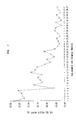
- Fig. 1 shows the weight change of silica in response to a variety of treatments involving sulfur monochloride and chlorine.
- Refractory oxide particles, or at least a portion thereof, are etched from, and/or dehydroxylation is performed on, a silica body by treatment with a gaseous mixture containing one or more non-oxygenated sulfur halides.
- treatment with a non-oxygenated sulfur halide indicates that the majority of the non-oxygenated sulfur halide is formed in a reactor or furnace or introduced into a reactor or furnace by a manner other than decomposition inside the reactor or furnace of an oxygenated sulfur halide.
- the process is advantageous in treatment of sol-gel derived substrate and/or overcladding tubes for optical fiber preforms, but treatment of other silica bodies is also contemplated.
- the sulfur halide contains one or more sulfur chlorides or sulfur chloro-fluorides, particularly since sulfur chlorides show a relatively high selectivity toward refractory materials relative to silica, such that refractory material particles are etched without substantial effect on the silica body, as reflected in the examples below. Also, it is contemplated that sulfur halides containing fluorine will be useful for down-doping substrate tubes with fluorine during the particle etching/dehydroxylation process, which would be desirable because fluorine doping is normally a relatively difficult process.
- the sulfur chlorides used for treatment of the sol-gel tube include sulfur monochloride (S 2 Cl 2 ) and sulfur dichloride (SCl 2 ).
- Sulfur dichloride is commercially available in bulk form as an impure chemical containing an equilibrium mixture of sulfur dichloride, sulfur monochloride, and chlorine (theoretically with about 85% sulfur dichloride).
- sulfur monochloride is commercially available in high purity. Because chlorine quantitatively converts elemental sulfur to sulfur dichloride, an equimolar mixture of chlorine gas and sulfur monochloride produces sulfur dichloride at a greater than 90% yield over a temperature range of 50 to 500°C (with a catalyst typically used at lower temperatures to facilitate the reaction). Therefore, a starting reagent mixture of a 1:1 ratio of Cl 2 :S 2 Cl 2 will produce sulfur dichloride as a desired reagent.
- Sulfur chlorides have the potential to generate undesirable gases if exposed to water, and thus on-demand production is desirable, as opposed to on-site storage of large quantities of sulfur chlorides.
- sulfur dichloride is capable of being produced from a chlorine/sulfur monochloride gas stream
- sulfur monochloride is capable of being generated on-demand. It is possible to generate sulfur monochloride by passing gaseous chlorine over molten sulfur, but the crude product of this reaction is generally contaminated with dissolved starting materials and also contains higher sulfur chlorides (see, e.g., J.W. Mellor, A Comprehensive Treatise on Inorganic and Theoretical Chemistry, Vol. 10, Longmans & Green Co., 1930, 631-684; F.
- Another possibility for on-demand formation of sulfur chlorides is in situ formation in the sol-gel bodies themselves. Specifically, it is possible to introduce sulfur into sol-gel bodies, e.g., by adding a sulfur-containing compound such as an organosulfur compound, an inorganic sulfur compound, or elemental sulfur to the silica mixture used to form the body, at any stage in the body's preparation. Chlorine gas is then flowed into a reactor containing the bodies to form one or more sulfur chlorides, and possibly a silica sulfur chloride. The non-sulfur components of the sulfur-containing compound are typically removed during the organic burnout step and/or purification and dehydroxylation of the body, with the particular requirements for removal depending on the sulfur-containing compound used. This in situ method has the potential to form higher sulfur chlorides, as discussed above.
- a sulfur-containing compound such as an organosulfur compound, an inorganic sulfur compound, or elemental sulfur
- Chlorine gas is then flowed into a reactor containing the bodies to form one or more sulfur
- the sulfur chlorides if flowed into a reaction furnace, are typically carried in a carrier gas that does not interfere with the reaction, i.e., does not prevent removal of refractory oxide particles and/or dehydroxylation.
- a carrier gas that does not interfere with the reaction, i.e., does not prevent removal of refractory oxide particles and/or dehydroxylation.
- gases such as helium, argon, and neon.
- Treatment with one or more sulfur chlorides is useful for dehydroxylating sol-gel bodies, e.g., removing hydroxyl groups and water, as well as removing refractory metal oxide particles (i.e., reducing their concentration) and/or reducing the size of such particles.
- refractory metal oxide particles i.e., reducing their concentration
- the chemical mechanisms by which the sulfur chlorides etch metal oxide particles are not known, but the etching of such particles is clear, as reflected in the examples below.
- Suitable process for treating sol-gel silica tubes e.g., having an inner diameter of about 20 mm, and outer diameter of about 70 mm
- dehydroxylate the tubes and/or remove refractory metal oxide particles are as follows.
- sol-gel tubes Tubes formed from a sol-gel process (hereafter, sol-gel tubes), such as U.S. Patent No. 5,240,488, referenced previously, are placed into a furnace capable of uniformly heating the tubes. It is possible for the tubes to be oriented either vertically or horizontally in the furnace. Typically, the tubes are placed into a quartz muffle inside the furnace, where the muffle is capable of withstanding pressure of 2 psi and has inlet and outlet ports such that gas is able to flow uniformly over the tubes.
- the furnace should be capable of uniformly heating the tubes at temperatures from 300 to 900°C, allowing for the temperature to be ramped up and down as desired, and the furnace and muffle should be constructed to prevent ambient air and moisture from entering.
- the tubes are treated with the gaseous mixture containing one or more non-oxygenated sulfur chlorides. It is possible to use any combination of sulfur chlorides, e.g., a single compound, such as sulfur monochloride, or a mixture of two or more sulfur chloride compounds, such as sulfur dichloride mixed with sulfur monochloride. It is possible to provide the sulfur chloride in several ways, e.g., flowing a sulfur chloride-containing gas into the furnace, or generating the sulfur chloride in situ, as discussed above.
- Dehydroxylation including removal of water and/or hydroxyl, as well as reduction of silanol, is typically performed (a) during the temperature ramp-up for particle removal, (b) after attainment of a desired temperature, or (c) by treating with chlorine gas instead of sulfur chloride.
- Reduction in the size of at least a portion of the refractory metal oxide particles and/or reduction of the particle concentration is typically performed as follows. As discussed more fully below, it is possible to perform a treatment with (a) sulfur chloride alone, or (b) a chlorine pre-treatment followed by sulfur chloride treatment, and (c) it is also possible to perform either (a) or (b) during the temperature ramp-up from a previous step of heating to remove water and organics.
- an oxygen treatment is generally performed. Chlorine is removed by replacement of chlorine atoms with oxygen atoms (i.e., replacing Si-Cl with Si-O-Si), since chlorine is an undesirable impurity in optical fiber. For example, it is possible to flow air or an oxygen/chlorine mixture over the tubes for 2 to 12 hours at temperature of 800 to 1000°C and at 10-100 slm.
- the etching efficiency of sulfur monochloride appears to be insensitive to the presence of oxygen in the reaction atmosphere, such that oxygen and sulfur chlorides are capable of being mixed without detrimental effects on particle removal.
- Etching rates of both refractory particle samples (Cr 2 O 3 and ZrO 2 ) and sample pellets of dried silica sol-gel were measured.
- Particle samples were obtained commercially, dispersed in a 0.1% xanthan gum solution in water plus a wetting agent, and ultrasonicated to ensure dispersion. The particles were then spread on a silica plate and dried at 100°C to remove the water.
- the silica sol-gel samples were prepared by conventional methods such as disclosed in U.S. Patent No. 5,240,488, referenced previously.
- the samples were placed in the center of a 4.2 cm outer diameter, 3.8 cm inner diameter quartz tube placed in a tube furnace, with mullite muffles placed in the tube near both ends of the furnace.
- Refractory particle samples were dispersed on a silica slide containing a grid.
- the change in refractory particle moles occurring due to various treatments was measured by taking photographs, at 320 ⁇ magnification, of the grid before and after the treatments, and measuring the diameter change.
- the molar loss calculations were based on the assumption that the particles were spheres and that etching occurred isotropically.
- the etching rates were calculated from the moles lost from the particles as a function of reaction time and reagent concentration.
- the effect of reagents on silica pellets was determined from weight loss measurements. Specifically, five sol-gel pellets (2.5 cm diameter ⁇ 1.6 cm thick) were placed in quartz boat, and the weight changes in the boat were measured after each reaction (within a few minutes of being removed from the furnace to prevent weight changes due to exposure to air).
- Reagent and buffer gases were introduced into the reaction chamber through calibrated mass flow controllers.
- Liquid reagents - sulfur monochloride (obtained from Aldrich, 98% pure) and thionyl chloride (obtained from Aldrich, 99+% pure) - were introduced by a conventional heated bubbler set-up, with nitrogen as the transport gas (at 125 sccm).
- Reagent gases of oxygen and chlorine were added downstream of the bubbler just before the furnace.
- Nitrogen (at 125 sccm) was also used as a buffer gas in some circumstances, in which case the nitrogen was introduced downstream of the bubbler.
- Table 1 shows the surface area normalized etching rates (KSA) for chromia particles, as a function of etching reagent, temperature, and particle size, for reagents of sulfur monochloride (S 2 Cl 2 ), Cl 2 plus sulfur monochloride, Cl 2 alone, and thionyl chloride.
- Table 2 shows the surface area normalized etching rates (K SA ) for zirconia particles, as a function of etching reagent, temperature, and particle size, for reagents of sulfur monochloride, Cl 2 plus sulfur monochloride, Cl 2 alone, and thionyl chloride.
- Tables 3 and 4 show the volume normalized etching rates (K V ) for chromia and zirconia particles, respectively, as a function of etching reagent and temperature, for a wide variety of particle sizes (about 3 to about 15 ⁇ m), for reagents of sulfur monochloride, Cl 2 plus sulfur monochloride, Cl 2 alone, and thionyl chloride.
- sulfur monochloride effectively etches both chromia and zirconia particles over temperatures ranging at least from 600 to 650°C, with the etching rates for zirconia being faster for equivalent reaction temperatures and sulfur monochloride concentrations.
- the Tables also show that chlorine is an effect etching agent, by itself, for chromia particles, but chlorine does not appear to etch zirconia to a measurable degree.
- the Tables indicate that the etching efficiency of sulfur monochloride appears to be insensitive to the presence of oxygen, in contrast to thionyl chloride.
- K SA Surface Area normalized etching rate for chromia particles (in moles/hr-m 2 ) Particle Size ⁇ Reagent - Temp. ⁇ 5 ⁇ m 8 ⁇ m 12 ⁇ m 12% Cl 2 - 950°C (0.5) (0.5) (0.5) 17% Cl 2 - 600°C 0.041 0.074 0.096 17% Cl 2 - 650°C 0.062 0.094 0.104 1.2% S 2 Cl 2 - 600°C 0.0026 0.0041 0.0054 1.2% S 2 Cl 2 - 650°C 0.0026 0.0053 0.0080 6.4% S 2 Cl 2 - 650°C 0.052 0.084 0.068 1.2% S 2 Cl 2 /3.1% Cl 2 - 650°C 0.0034 0.0048 0.0071 1.2% S 2 Cl 2 /17% Cl 2 - 600°C 0.0027 0.0043 0.0055 1.2% S 2 Cl 2 /17% Cl 2 - 650°C 0.0025 0.0042 0.0084 17% S 2 Cl
- the silica pellets Prior to reactivity measurements, the silica pellets underwent an organic burnout, and were then dehydroxylated by a chlorine treatment such as described above.
- the silica pellets were subjected to various treatments by chlorine, oxygen, and/or sulfur monochloride to monitor the treatments' effects on silica, as reflected in Table 5, with the weight after each Run plotted in Fig. 1.
- weight increases result from processing step 1 - reaction with chlorine without subsequent processing.
- the weight decrease seen at Run 2 is due to removal of a relatively substantial amount of water from the pellets.
- Weight decreases generally result from processing steps 2 and 3 - reaction with chlorine, followed by reaction with oxygen alone or oxygen and sulfur monochloride. Initially, therefore, it appears that the chlorine dehydroxylates the silica, replacing -OH with -Cl. Oxygen treatment then appears to replace, at least partially, chlorine with oxygen.
- sulfur monochloride does not appear to attack the silica at the 650°C processing temperature, since a stable weight was reached by process 3 such that subsequent processing by process 2 produced no additional weight loss. This conclusion is further supported in that process 2 and 3 produced substantially identical weight decreases when performed on silica pellets.
Landscapes
- Chemical & Material Sciences (AREA)
- Engineering & Computer Science (AREA)
- Chemical Kinetics & Catalysis (AREA)
- Manufacturing & Machinery (AREA)
- Materials Engineering (AREA)
- Organic Chemistry (AREA)
- Physics & Mathematics (AREA)
- General Chemical & Material Sciences (AREA)
- Life Sciences & Earth Sciences (AREA)
- Thermal Sciences (AREA)
- General Life Sciences & Earth Sciences (AREA)
- Geochemistry & Mineralogy (AREA)
- Dispersion Chemistry (AREA)
- Inorganic Compounds Of Heavy Metals (AREA)
- Manufacture, Treatment Of Glass Fibers (AREA)
Applications Claiming Priority (2)
| Application Number | Priority Date | Filing Date | Title |
|---|---|---|---|
| US109827 | 1993-08-20 | ||
| US09/109,827 US6334338B1 (en) | 1998-07-02 | 1998-07-02 | Sol gel process of making a fiber preform with removal of oxide particles |
Publications (2)
| Publication Number | Publication Date |
|---|---|
| EP0968972A1 true EP0968972A1 (de) | 2000-01-05 |
| EP0968972B1 EP0968972B1 (de) | 2001-09-19 |
Family
ID=22329771
Family Applications (1)
| Application Number | Title | Priority Date | Filing Date |
|---|---|---|---|
| EP99305104A Expired - Lifetime EP0968972B1 (de) | 1998-07-02 | 1999-06-29 | Verfahren zum Herstellen einer optischen Faser |
Country Status (4)
| Country | Link |
|---|---|
| US (2) | US6334338B1 (de) |
| EP (1) | EP0968972B1 (de) |
| JP (1) | JP3524435B2 (de) |
| DE (1) | DE69900295T2 (de) |
Cited By (3)
| Publication number | Priority date | Publication date | Assignee | Title |
|---|---|---|---|---|
| WO2000068718A1 (en) * | 1999-05-07 | 2000-11-16 | Corning Incorporated | Chalcogenide doping of oxide glasses |
| US6542690B1 (en) | 2000-05-08 | 2003-04-01 | Corning Incorporated | Chalcogenide doping of oxide glasses |
| WO2004050571A1 (en) * | 2002-12-04 | 2004-06-17 | Corning Incorporated | Method for reducing metal impurities in optical fiber soot preforms |
Families Citing this family (7)
| Publication number | Priority date | Publication date | Assignee | Title |
|---|---|---|---|---|
| JP2004307280A (ja) * | 2003-04-08 | 2004-11-04 | Shin Etsu Chem Co Ltd | Oh基による吸収を減少した光ファイバ用ガラス母材及びその製造方法 |
| BRPI0407097A (pt) * | 2003-04-23 | 2006-01-24 | Japan Tobacco Inc | Antagonista do casr |
| US8132429B2 (en) * | 2004-04-27 | 2012-03-13 | Silitec Fibers Sa | Method for fabricating an optical fiber, preform for fabricating an optical fiber, optical fiber and apparatus |
| US7854143B2 (en) * | 2006-12-22 | 2010-12-21 | Ofs Fitel Llc | Optical fiber preform with improved air/glass interface structure |
| EP2603467B1 (de) | 2010-08-12 | 2020-09-30 | Corning Incorporated | Behandlung von russ auf kieselsäurebasis oder eines artikels aus russ auf kieselsäurebasis |
| WO2016153508A1 (en) * | 2015-03-25 | 2016-09-29 | Shasta Crystals, Inc. | Sol-gel cladding for optical fiber |
| JP7613805B2 (ja) * | 2020-10-12 | 2025-01-15 | 東京エレクトロン株式会社 | 埋め込み方法及び成膜装置 |
Citations (7)
| Publication number | Priority date | Publication date | Assignee | Title |
|---|---|---|---|---|
| JPS56100145A (en) * | 1980-01-07 | 1981-08-11 | Nippon Telegr & Teleph Corp <Ntt> | Manufacture of quartz glass |
| EP0140651A1 (de) * | 1983-10-19 | 1985-05-08 | Sumitomo Electric Industries Limited | Verfahren zur Herstellung einer Glasvorform für optische Fasern |
| GB2165233A (en) * | 1984-10-04 | 1986-04-09 | Suwa Seikosha Kk | Method of making a tubular silica glass member |
| JPS6469532A (en) * | 1987-09-08 | 1989-03-15 | Sumitomo Electric Industries | Production of glass |
| JPH01164740A (ja) * | 1987-12-22 | 1989-06-28 | Sumitomo Electric Ind Ltd | 光フアイバ用母材の製造方法 |
| JPH0477327A (ja) * | 1990-07-17 | 1992-03-11 | Sumitomo Electric Ind Ltd | 光ファイバの製造方法 |
| EP0614856A1 (de) * | 1993-03-11 | 1994-09-14 | AT&T Corp. | Herstellung von stark geprüfter optischer Faser mittels Sol-Gel |
Family Cites Families (19)
| Publication number | Priority date | Publication date | Assignee | Title |
|---|---|---|---|---|
| GB140651A (en) | 1919-05-22 | 1920-04-01 | Albert Joseph Rath | Improved construction of piston |
| GB614856A (en) | 1946-08-06 | 1948-12-23 | Tetra Engineering Co Ltd | Improvements in and relating to cut-outs for electrically heated devices |
| US4909816A (en) | 1974-02-22 | 1990-03-20 | American Telephone And Telegraph Company, At&T Bell Laboratories | Optical fiber fabrication and resulting product |
| US4217027A (en) | 1974-02-22 | 1980-08-12 | Bell Telephone Laboratories, Incorporated | Optical fiber fabrication and resulting product |
| JPS5510412A (en) | 1978-07-06 | 1980-01-24 | Nippon Telegr & Teleph Corp <Ntt> | Production of anhydrous glass base material for optical fiber |
| JPS5924092B2 (ja) * | 1978-12-29 | 1984-06-07 | 三菱マテリアル株式会社 | 光フアイバ母材の製造法 |
| JPS5688836A (en) | 1979-12-20 | 1981-07-18 | Nippon Telegr & Teleph Corp <Ntt> | Preparation of glass stock for optical fiber |
| US4262035A (en) | 1980-03-07 | 1981-04-14 | Bell Telephone Laboratories, Incorporated | Modified chemical vapor deposition of an optical fiber using an rf plasma |
| US4426216A (en) | 1982-01-06 | 1984-01-17 | Hitachi, Ltd. | Process for producing optical glass |
| JP2549615B2 (ja) * | 1984-06-18 | 1996-10-30 | 住友電気工業株式会社 | 光フアイバ用ガラス母材の焼結方法 |
| JPS6136129A (ja) | 1984-07-30 | 1986-02-20 | Sumitomo Electric Ind Ltd | 光フアイバ用ガラス母材の製造方法 |
| JPS61174146A (ja) | 1985-01-25 | 1986-08-05 | Sumitomo Electric Ind Ltd | 光フアイバ及びその製造方法 |
| JPS61183142A (ja) | 1985-02-09 | 1986-08-15 | Fujikura Ltd | ガラスキヤピラリイの製造方法 |
| EP0542724B1 (de) * | 1987-02-16 | 1996-06-12 | Sumitomo Electric Industries Limited | Ofen zum Erhitzen einer Glasvorform für optische Faser und Verfahren zum Herstellen einer Glasvorform |
| JPS63225543A (ja) | 1987-03-13 | 1988-09-20 | Furukawa Electric Co Ltd:The | 光フアイバ母材の製造方法 |
| US4775401A (en) | 1987-06-18 | 1988-10-04 | American Telephone And Telegraph Company, At&T Bell Laboratories | Method of producing an optical fiber |
| JP3106564B2 (ja) | 1991-07-24 | 2000-11-06 | 住友電気工業株式会社 | 光ファイバの製造方法及び石英系光ファイバ |
| US5240488A (en) | 1992-08-14 | 1993-08-31 | At&T Bell Laboratories | Manufacture of vitreous silica product via a sol-gel process using a polymer additive |
| US5344475A (en) | 1993-03-11 | 1994-09-06 | At&T Bell Laboratories | Manufacture of high proof-test optical fiber using sol-gel |
-
1998
- 1998-07-02 US US09/109,827 patent/US6334338B1/en not_active Expired - Lifetime
-
1999
- 1999-06-29 DE DE69900295T patent/DE69900295T2/de not_active Expired - Lifetime
- 1999-06-29 EP EP99305104A patent/EP0968972B1/de not_active Expired - Lifetime
- 1999-06-30 JP JP18579599A patent/JP3524435B2/ja not_active Expired - Fee Related
-
2001
- 2001-07-24 US US09/912,129 patent/US6748767B2/en not_active Expired - Fee Related
Patent Citations (7)
| Publication number | Priority date | Publication date | Assignee | Title |
|---|---|---|---|---|
| JPS56100145A (en) * | 1980-01-07 | 1981-08-11 | Nippon Telegr & Teleph Corp <Ntt> | Manufacture of quartz glass |
| EP0140651A1 (de) * | 1983-10-19 | 1985-05-08 | Sumitomo Electric Industries Limited | Verfahren zur Herstellung einer Glasvorform für optische Fasern |
| GB2165233A (en) * | 1984-10-04 | 1986-04-09 | Suwa Seikosha Kk | Method of making a tubular silica glass member |
| JPS6469532A (en) * | 1987-09-08 | 1989-03-15 | Sumitomo Electric Industries | Production of glass |
| JPH01164740A (ja) * | 1987-12-22 | 1989-06-28 | Sumitomo Electric Ind Ltd | 光フアイバ用母材の製造方法 |
| JPH0477327A (ja) * | 1990-07-17 | 1992-03-11 | Sumitomo Electric Ind Ltd | 光ファイバの製造方法 |
| EP0614856A1 (de) * | 1993-03-11 | 1994-09-14 | AT&T Corp. | Herstellung von stark geprüfter optischer Faser mittels Sol-Gel |
Non-Patent Citations (4)
| Title |
|---|
| CHEMICAL ABSTRACTS, vol. 112, no. 8, 19 February 1990, Columbus, Ohio, US; abstract no. 61546, XP002115418 * |
| PATENT ABSTRACTS OF JAPAN vol. 13, no. 273 22 June 1989 (1989-06-22) * |
| PATENT ABSTRACTS OF JAPAN vol. 16, no. 289 26 June 1992 (1992-06-26) * |
| PATENT ABSTRACTS OF JAPAN vol. 5, no. 178 14 November 1981 (1981-11-14) * |
Cited By (5)
| Publication number | Priority date | Publication date | Assignee | Title |
|---|---|---|---|---|
| WO2000068718A1 (en) * | 1999-05-07 | 2000-11-16 | Corning Incorporated | Chalcogenide doping of oxide glasses |
| US6760526B2 (en) | 1999-05-19 | 2004-07-06 | Corning Incorporated | Chalcogenide doping of oxide glasses |
| US6542690B1 (en) | 2000-05-08 | 2003-04-01 | Corning Incorporated | Chalcogenide doping of oxide glasses |
| WO2004050571A1 (en) * | 2002-12-04 | 2004-06-17 | Corning Incorporated | Method for reducing metal impurities in optical fiber soot preforms |
| US6935050B2 (en) | 2002-12-04 | 2005-08-30 | Corning Incorporated | Method and apparatus reducing metal impurities in optical fiber soot preforms |
Also Published As
| Publication number | Publication date |
|---|---|
| US6334338B1 (en) | 2002-01-01 |
| US6748767B2 (en) | 2004-06-15 |
| DE69900295T2 (de) | 2002-07-04 |
| DE69900295D1 (de) | 2001-10-25 |
| JP3524435B2 (ja) | 2004-05-10 |
| US20020023466A1 (en) | 2002-02-28 |
| EP0968972B1 (de) | 2001-09-19 |
| JP2000086266A (ja) | 2000-03-28 |
Similar Documents
| Publication | Publication Date | Title |
|---|---|---|
| US4979971A (en) | Method for producing glass preform for optical fiber | |
| US5221309A (en) | Method for producing glass preform for optical fiber | |
| US4082420A (en) | An optical transmission fiber containing fluorine | |
| US6109065A (en) | Method of making optical waveguide devices using perchloryl fluoride to make soot | |
| JPH03131544A (ja) | 光ファイバ用ガラス母材の加熱炉および製法 | |
| US4161505A (en) | Process for producing optical transmission fiber | |
| US6748767B2 (en) | Drawing an optical fiber from a sol-gel preform treated with a non-oxygenated sulfur halide | |
| US4295869A (en) | Process for producing optical transmission fiber | |
| US20200262736A1 (en) | Method of producing optical fiber preform and optical fiber | |
| US4165152A (en) | Process for producing optical transmission fiber | |
| EP0167054B1 (de) | Verfahren zum Herstellen einer Vorform für eine optische Faser | |
| JP2808857B2 (ja) | 光ファイバ用ガラス母材の加熱炉および製法 | |
| US20020108404A1 (en) | Drying agent and improved process for drying soot preforms | |
| CN1863733A (zh) | 高纯度的热解制备的二氧化硅 | |
| EP0164127B1 (de) | Verfahren zur Herstellung einer Glasvorform für optische Fasern | |
| KR100430704B1 (ko) | 불소 도핑된 졸-겔 제품의 제조방법 | |
| WO2022209515A1 (ja) | フッ素含有シリカガラス粉、及びフッ素含有シリカガラス粉の製造方法 | |
| JP2022031249A (ja) | フッ素化石英ガラスの製造のための代替フッ素化剤 | |
| JPS6289B2 (de) | ||
| JPH0425212B2 (de) | ||
| JPH0813689B2 (ja) | 光ファイバ用母材の製造方法 | |
| JPS63315531A (ja) | 光ファイバ母材の製造方法 | |
| PAUL | OXIDATION-REDUCTION EQUILIBRIUM DURING PREFORM MAKING OF OPTICAL FIBRE | |
| JPH03103332A (ja) | 光ファイバ用ガラス母材の加熱炉および製法 | |
| JP2020532482A (ja) | エッチングガスおよび中和ガスを使用して光ファイバプリフォームを調製するための方法および炉 |
Legal Events
| Date | Code | Title | Description |
|---|---|---|---|
| PUAI | Public reference made under article 153(3) epc to a published international application that has entered the european phase |
Free format text: ORIGINAL CODE: 0009012 |
|
| 17P | Request for examination filed |
Effective date: 19990709 |
|
| AK | Designated contracting states |
Kind code of ref document: A1 Designated state(s): DE GB |
|
| AX | Request for extension of the european patent |
Free format text: AL;LT;LV;MK;RO;SI |
|
| 17Q | First examination report despatched |
Effective date: 20000201 |
|
| AKX | Designation fees paid |
Free format text: DE GB |
|
| GRAG | Despatch of communication of intention to grant |
Free format text: ORIGINAL CODE: EPIDOS AGRA |
|
| GRAG | Despatch of communication of intention to grant |
Free format text: ORIGINAL CODE: EPIDOS AGRA |
|
| GRAH | Despatch of communication of intention to grant a patent |
Free format text: ORIGINAL CODE: EPIDOS IGRA |
|
| GRAH | Despatch of communication of intention to grant a patent |
Free format text: ORIGINAL CODE: EPIDOS IGRA |
|
| GRAA | (expected) grant |
Free format text: ORIGINAL CODE: 0009210 |
|
| AK | Designated contracting states |
Kind code of ref document: B1 Designated state(s): DE GB |
|
| REF | Corresponds to: |
Ref document number: 69900295 Country of ref document: DE Date of ref document: 20011025 |
|
| REG | Reference to a national code |
Ref country code: GB Ref legal event code: IF02 |
|
| PLBE | No opposition filed within time limit |
Free format text: ORIGINAL CODE: 0009261 |
|
| STAA | Information on the status of an ep patent application or granted ep patent |
Free format text: STATUS: NO OPPOSITION FILED WITHIN TIME LIMIT |
|
| 26N | No opposition filed | ||
| PGFP | Annual fee paid to national office [announced via postgrant information from national office to epo] |
Ref country code: DE Payment date: 20130620 Year of fee payment: 15 Ref country code: GB Payment date: 20130619 Year of fee payment: 15 |
|
| REG | Reference to a national code |
Ref country code: GB Ref legal event code: 732E Free format text: REGISTERED BETWEEN 20131031 AND 20131106 |
|
| REG | Reference to a national code |
Ref country code: DE Ref legal event code: R119 Ref document number: 69900295 Country of ref document: DE |
|
| GBPC | Gb: european patent ceased through non-payment of renewal fee |
Effective date: 20140629 |
|
| REG | Reference to a national code |
Ref country code: DE Ref legal event code: R119 Ref document number: 69900295 Country of ref document: DE Effective date: 20150101 |
|
| PG25 | Lapsed in a contracting state [announced via postgrant information from national office to epo] |
Ref country code: DE Free format text: LAPSE BECAUSE OF NON-PAYMENT OF DUE FEES Effective date: 20150101 |
|
| PG25 | Lapsed in a contracting state [announced via postgrant information from national office to epo] |
Ref country code: GB Free format text: LAPSE BECAUSE OF NON-PAYMENT OF DUE FEES Effective date: 20140629 |