EP0969144A1 - Procédé et dispositif de fabrication de papier ayant des moyens pour éliminer les ébardures, et toile pour cette machine - Google Patents
Procédé et dispositif de fabrication de papier ayant des moyens pour éliminer les ébardures, et toile pour cette machine Download PDFInfo
- Publication number
- EP0969144A1 EP0969144A1 EP99111641A EP99111641A EP0969144A1 EP 0969144 A1 EP0969144 A1 EP 0969144A1 EP 99111641 A EP99111641 A EP 99111641A EP 99111641 A EP99111641 A EP 99111641A EP 0969144 A1 EP0969144 A1 EP 0969144A1
- Authority
- EP
- European Patent Office
- Prior art keywords
- belt
- tissue
- belts
- impermeable
- mesh
- Prior art date
- Legal status (The legal status is an assumption and is not a legal conclusion. Google has not performed a legal analysis and makes no representation as to the accuracy of the status listed.)
- Withdrawn
Links
- 238000000034 method Methods 0.000 title claims abstract description 16
- 238000009966 trimming Methods 0.000 title claims abstract description 15
- 238000004519 manufacturing process Methods 0.000 title claims abstract description 9
- 239000000835 fiber Substances 0.000 claims abstract description 27
- 239000000203 mixture Substances 0.000 claims abstract description 24
- 238000005520 cutting process Methods 0.000 claims abstract description 11
- 239000007788 liquid Substances 0.000 claims abstract description 8
- 239000002657 fibrous material Substances 0.000 claims abstract description 5
- 230000000694 effects Effects 0.000 claims description 8
- 239000000463 material Substances 0.000 claims description 5
- 229920002994 synthetic fiber Polymers 0.000 claims description 3
- XLYOFNOQVPJJNP-UHFFFAOYSA-N water Substances O XLYOFNOQVPJJNP-UHFFFAOYSA-N 0.000 description 31
- 238000010586 diagram Methods 0.000 description 7
- 239000004744 fabric Substances 0.000 description 7
- 229920003043 Cellulose fiber Polymers 0.000 description 4
- 238000001035 drying Methods 0.000 description 4
- 230000009471 action Effects 0.000 description 3
- 230000008569 process Effects 0.000 description 2
- 230000002787 reinforcement Effects 0.000 description 2
- 230000002745 absorbent Effects 0.000 description 1
- 239000002250 absorbent Substances 0.000 description 1
- 238000010521 absorption reaction Methods 0.000 description 1
- 239000000969 carrier Substances 0.000 description 1
- 238000010924 continuous production Methods 0.000 description 1
- 239000012530 fluid Substances 0.000 description 1
- 238000012423 maintenance Methods 0.000 description 1
- 238000012986 modification Methods 0.000 description 1
- 230000004048 modification Effects 0.000 description 1
- 229920003023 plastic Polymers 0.000 description 1
- 239000004033 plastic Substances 0.000 description 1
- 229920000728 polyester Polymers 0.000 description 1
- 229920002635 polyurethane Polymers 0.000 description 1
- 239000004814 polyurethane Substances 0.000 description 1
- 238000003825 pressing Methods 0.000 description 1
- 238000005507 spraying Methods 0.000 description 1
- 229920003002 synthetic resin Polymers 0.000 description 1
- 239000000057 synthetic resin Substances 0.000 description 1
- 239000004753 textile Substances 0.000 description 1
Images


Classifications
-
- D—TEXTILES; PAPER
- D21—PAPER-MAKING; PRODUCTION OF CELLULOSE
- D21F—PAPER-MAKING MACHINES; METHODS OF PRODUCING PAPER THEREON
- D21F1/00—Wet end of machines for making continuous webs of paper
- D21F1/58—Deckle straps
-
- D—TEXTILES; PAPER
- D21—PAPER-MAKING; PRODUCTION OF CELLULOSE
- D21F—PAPER-MAKING MACHINES; METHODS OF PRODUCING PAPER THEREON
- D21F7/00—Other details of machines for making continuous webs of paper
- D21F7/006—Cutting the edges of the paper-web
-
- D—TEXTILES; PAPER
- D21—PAPER-MAKING; PRODUCTION OF CELLULOSE
- D21F—PAPER-MAKING MACHINES; METHODS OF PRODUCING PAPER THEREON
- D21F9/00—Complete machines for making continuous webs of paper
- D21F9/003—Complete machines for making continuous webs of paper of the twin-wire type
Definitions
- the present invention relates to a machine for the continuous manufacture of a tissue or web of paper or other fibrous material starting from mixtures of fibers and water or other liquid carriers, with a means for eliminating edge trimmings.
- the present invention also relates to a method for eliminating edge trimmings from a paper-like material in web or ribbon form, in a machine for manufacturing it.
- the present invention also relates to a mesh or fabric for use in a machine of the above mentioned type.
- the mixture of fibers and water is fed into a gap between adjacent guiding rollers on which two meshes are guided.
- the mixture accordingly forms a thin tissue of water and fibers.
- the percentage of water in the mixture is reduced from an initial value of approximately 99% to a final value of approximately 50% by weight.
- the water is drained through the textile structure of the mesh.
- the resulting tissue of fibers is then passed onto a further belt which is thicker, has high absorption properties and is known as felt. Then the tissue is transferred to a drying means of the thermal type, for example by guiding the tissue on a so-called Yankee cylinder which is internally heated with a suitable heat-conveying fluid, in order to obtain a paper web in output from the unit.
- the longitudinal edges of the tissue formed between the two adjacent meshes are uneven and must be eliminated.
- Pressurized water nozzles are currently used for this purpose.
- the nozzles are arranged in a region in which the already partially dehydrated tissue rests on one of the fabrics, while the other surface is free and exposed to the action of the nozzle.
- the water that cuts the tissue is discharged through the mesh on which the tissue rests.
- tissue paper In another type of paper-making machine, the mixture of water and fibers is fed between a felt and a mesh. The tissue, partially dehydrated by drainage through the mesh, clings to the felt and is conveyed by it to a heated Yankee cylinder.
- tissue paper that is to say, paper adapted to the subsequent production of kitchen paper rolls, napkins, handkerchiefs, toilet paper and the like.
- the longitudinal edge trimmings of the tissue are cut by water-spraying nozzles in this kind of machine as well.
- the nozzles act on the tissue while it clings to the felt. This entails the drawback that discharge of the water used for cutting is difficult because the felt is practically impermeable to water. Furthermore, the jet of water that reaches the felt causes it to wear rapidly.
- the aim of the present invention is to provide a new method for eliminating longitudinal edge trimmings from paper tissues being formed in continuous machines.
- Another object of the present invention is to provide a machine and corresponding accessories for performing the method.
- an object of the present invention is to provide a method and a machine which allow to eliminate edge trimmings from the paper tissue being formed without using nozzles or other mechanical components that are expensive and difficult to maintain, and are therefore more reliable and cheaper.
- Another object of the present invention is to provide a method for eliminating edge trimmings which is particularly suitable for use in machines of the crescent former type, in which the discharge of the water sprayed by conventional cutting nozzles is particularly difficult.
- Another object of the present invention is to provide a new type of mesh for machines for manufacturing paper or other tissues of fibrous material starting from mixtures of fibers and a liquid carrier such as water or the like.
- the method according to the invention is based on the recognition of the fact that by providing a nondraining region along the mesh of the paper-making machine the fibers contained in the mixture pressed between the mesh and the felt, or between two meshes, tend to migrate due to the hydraulic counterpressure generated in the nondraining region. This produces, between the two belts, a region which has no fibers and in which the paper tissue accordingly does not form. If the nondraining region is obtained by virtue of a longitudinal strip of appropriate size located proximate to the edge of the tissue being formed between the two belts, a cutting line forms at the strip which separates the longitudinal edge trimming from the rest of the tissue being formed.
- the invention also relates to a machine for manufacturing paper comprising: a first pervious moving belt; a second moving belt which cooperates with the first belt, the first belt and the second belt being able to move along respective closed paths which have a common portion along which the two belts are pressed against each other.
- a machine for manufacturing paper comprising: a first pervious moving belt; a second moving belt which cooperates with the first belt, the first belt and the second belt being able to move along respective closed paths which have a common portion along which the two belts are pressed against each other.
- at least one longitudinal impermeable strip is formed on the first pervious belt; at the strip, the pressure between the two belts produces a parting of the fibers, generating a discontinuity line in the tissue being formed.
- the first belt can be constituted by a mesh made of synthetic fabric through the stitches of which the liquid of the mixture drains away.
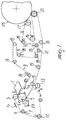
- the present invention is applied particularly advantageously in machines of the crescent former type, a diagram of which is shown in Fig. 1.
- the reference numeral 1 generally designates a container from which the mixture of water and cellulose fibers is dispensed through a longitudinal slit. The mixture is dispensed in a gap between two rollers 3 and 5, around which a mesh 7 and a felt 9 are guided respectively.
- the mesh 7 is guided not only around the roller 3 but also around additional rollers 11, 12 and 13 as well as around the roller 5, a portion of which is accordingly surrounded both by the felt 9 and by the mesh 7.
- the mesh 7 advances in the direction indicated by the arrow f7 and the felt advances in the direction indicated by the arrow f9.
- the felt 9 covers a longer path than the fabric 7 which is determined by a series of rollers 15, 16, 17, 18, 19, 21.
- the mixture fed continuously from the container 1 and constituted by approximately 99% water by weight and 1% cellulose fiber by weight, is pressed in the gap between the rollers 3 and 5 and forms a continuous tissue 10 between the mesh 7 and the felt 9.
- the guiding of the mesh 7 and of the felt 9, with the tissue interposed between them, around the roller 5 causes the drainage of water through the mesh 7 due to centrifugal force.
- the discharged water is collected in a tank 23.
- the mesh 7 and the felt 9 are caused to mutually diverge, since the roller 13 and the first one of the rollers 15 are mutually spaced.
- the paper tissue being formed continues to adhere to the surface of the absorbent felt 9 and is conveyed to the cylinder 21, which constitutes, together with a large-diameter cylinder 25 which is known as Yankee cylinder, a rotary press for eliminating by pressing a further fraction of water from the tissue being formed.
- the tissue is then transferred from the felt 9 to the surface of the Yankee cylinder 25 for the subsequent thermal drying treatment.
- these nozzles are instead eliminated and replaced with a different cutting system described hereinafter.
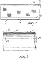
- a longitudinal impermeable strip is provided parallel to each edge 7A (Fig. 7) of the mesh 7 and at a preset distance from the edge and closes the draining region of the fabric over a preset width.
- the impermeable strip is typically made of a synthetic resin which is applied hot or cold.
- meshes made of polyester or other suitable and per se known material it is possible to provide impermeable strips of polyurethane, which are particularly advantageous due to their high adhesion to the mesh and to their considerable elasticity, which makes the mesh resistant to wear.
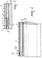
- the impermeable strip is designated by the reference numeral 31.
- Fig. 7 which shows a portion of mesh extended flat, illustrates two strips 31 which are parallel to the two longitudinal edges 7A of the mesh. The figs. are not to scale and the dimensions of the felt, of the mesh, of the mixture C and of the strip 31 have been altered for the sake of a clearer graphic presentation.
- the fibers "migrate" from the region I toward the adjacent regions, so that in the region I between the impermeable strip 31 and the surface of the felt 9 there forms a volume without cellulose fibers which contains practically only water. In this region, the fiber tissue does not form because there are no fibers and this produces a longitudinal cutting line which runs approximately so as to correspond to the extension of the strip 31.
- This hydraulic effect can also optionally be combined with a mechanical effect due to the fact that the strip 31 protrudes with respect to the surface of the mesh 7 and presses against the surface of the felt 9 to which the tissue C adheres.
- tissue C is produced whose width is equal to the distance between the inner edges of the two strips 31 and has trimmed longitudinal edges.
- the dimensions of the strips 31 can vary also according to the type of mixture used. Typically, appreciable results have been obtained with strips 31 which have a width L of approximately 2-7 mm and a height H of approximately 0.5-1.5 mm. Optimum results are achieved with strips approximately 4 mm wide and approximately 1 mm high. These dimensions are different from those of the plastic-coated strips commonly used as reinforcement members in some kinds of mesh. In that case the reinforcement strips are much smaller and are used in large numbers because they must not block the draining region of the mesh.
- Figs. 4 and 5 show two different diagrams of a paper-making machine.
- the mixture of fibers and water is fed by a container, again designated by the reference numeral 1, into a gap formed between two meshes 41, 43 which are guided around two rollers 45, 47.
- the mixture forms a tissue between the two meshes 41 and 43; the tissue is centrifuged in the region in which the meshes are guided around the roller 47.
- the water drained through the mesh 41 is discharged into a collection tank 49 which has the same functions as the tank 23.
- the partially dried tissue is then transferred from the mesh 41 to a felt 51 which conveys it to a thermal drying means, such as a drying section or a Yankee cylinder.
- a thermal drying means such as a drying section or a Yankee cylinder.
- Fig. 5 The diagram of Fig. 5 is conceptually similar and differs from the diagram of Fig. 4 in the arrangement of the meshes and of the felt. Identical or corresponding parts are designated by the same reference numerals used in Fig. 4.
- the cutting system according to the present invention can be used whenever, in a region of the path of the tissue being formed in which the tissue is still constituted by a mixture with a high percentage of water with respect to the fiber, the tissue lies between a draining surface constituted by the mesh provided with impermeable strips and a nondraining surface.
- the nondraining surface can be constituted by a belt-like part which is impervious or scarcely pervious (such as a felt) or by a mesh which rests on an impervious guiding surface (such as the surface of the roller 47 in Figs. 4 and 5).
- the materials used, as well as the dimensions, may be any according to the requirements and the state of the art.
Landscapes
- Paper (AREA)
Applications Claiming Priority (2)
| Application Number | Priority Date | Filing Date | Title |
|---|---|---|---|
| ITMI981533 | 1998-07-03 | ||
| ITMI981533 ITMI981533A1 (it) | 1998-07-03 | 1998-07-03 | Macchina per la produzione di carta con mezzi ler l'eliminazione dei rifili relativo metodo di produzione e tela per detta macchina |
Publications (1)
| Publication Number | Publication Date |
|---|---|
| EP0969144A1 true EP0969144A1 (fr) | 2000-01-05 |
Family
ID=11380376
Family Applications (1)
| Application Number | Title | Priority Date | Filing Date |
|---|---|---|---|
| EP99111641A Withdrawn EP0969144A1 (fr) | 1998-07-03 | 1999-06-16 | Procédé et dispositif de fabrication de papier ayant des moyens pour éliminer les ébardures, et toile pour cette machine |
Country Status (4)
| Country | Link |
|---|---|
| EP (1) | EP0969144A1 (fr) |
| JP (1) | JP2000034688A (fr) |
| CA (1) | CA2276817A1 (fr) |
| IT (1) | ITMI981533A1 (fr) |
Cited By (2)
| Publication number | Priority date | Publication date | Assignee | Title |
|---|---|---|---|---|
| WO2001004413A1 (fr) * | 1999-07-12 | 2001-01-18 | Geschmay Corp. | Systeme coupe-bordure pour toiles de machines a papier |
| WO2009096850A1 (fr) * | 2008-02-01 | 2009-08-06 | Metso Paper Inc. | Toile de machine à papier et procédés associés incluant la toile |
Families Citing this family (1)
| Publication number | Priority date | Publication date | Assignee | Title |
|---|---|---|---|---|
| CN101506434B (zh) * | 2006-08-10 | 2012-09-05 | 梅特索·佩珀·卡尔斯塔德公司 | 造纸机成型部中的单元以及用于组装该成型部的方法 |
Citations (1)
| Publication number | Priority date | Publication date | Assignee | Title |
|---|---|---|---|---|
| FR1556210A (fr) * | 1966-07-19 | 1969-02-07 |
-
1998
- 1998-07-03 IT ITMI981533 patent/ITMI981533A1/it unknown
-
1999
- 1999-06-16 EP EP99111641A patent/EP0969144A1/fr not_active Withdrawn
- 1999-06-30 CA CA 2276817 patent/CA2276817A1/fr not_active Abandoned
- 1999-07-01 JP JP11187918A patent/JP2000034688A/ja active Pending
Patent Citations (1)
| Publication number | Priority date | Publication date | Assignee | Title |
|---|---|---|---|---|
| FR1556210A (fr) * | 1966-07-19 | 1969-02-07 |
Cited By (7)
| Publication number | Priority date | Publication date | Assignee | Title |
|---|---|---|---|---|
| WO2001004413A1 (fr) * | 1999-07-12 | 2001-01-18 | Geschmay Corp. | Systeme coupe-bordure pour toiles de machines a papier |
| WO2009096850A1 (fr) * | 2008-02-01 | 2009-08-06 | Metso Paper Inc. | Toile de machine à papier et procédés associés incluant la toile |
| EP2250316A4 (fr) * | 2008-02-01 | 2011-07-20 | Albany Int Corp | Toile de machine à papier et procédés associés incluant la toile |
| US8241464B2 (en) | 2008-02-01 | 2012-08-14 | Albany International Corp. | Papermaking clothing defining a width of a paper web and associated system and method |
| RU2508427C2 (ru) * | 2008-02-01 | 2014-02-27 | Олбани Интернешнл Корп. | Ткань для бумагоделательной машины и связанные с ней способы |
| US8758568B2 (en) | 2008-02-01 | 2014-06-24 | Albany International Corp. | Papermaking clothing defining a width of a paper web and associated system and method |
| KR101535315B1 (ko) * | 2008-02-01 | 2015-07-08 | 알바니 인터내셔널 코포레이션 | 제지 직물과 이를 제조하기 위한 장치 및 방법 |
Also Published As
| Publication number | Publication date |
|---|---|
| CA2276817A1 (fr) | 2000-01-03 |
| JP2000034688A (ja) | 2000-02-02 |
| ITMI981533A1 (it) | 2000-01-03 |
Similar Documents
| Publication | Publication Date | Title |
|---|---|---|
| CA2374923C (fr) | Machine a papier pour former du papier menager mettant en oeuvre une presse a air | |
| EP0854229A3 (fr) | Machine pour la fabrication d'une bande fibreuse | |
| US4257844A (en) | Press section arrangement | |
| CA2109781A1 (fr) | Section des presses d'une machine a papier | |
| US3824152A (en) | Twin wire paper forming with one wire wrapping a suction cylinder | |
| EP0969144A1 (fr) | Procédé et dispositif de fabrication de papier ayant des moyens pour éliminer les ébardures, et toile pour cette machine | |
| GB1589800A (en) | Tissue paper-making machine | |
| GB931976A (en) | Improvements in or relating to paper-making machines | |
| FI77492B (fi) | Foerfarande och anordning foer att saenka energiaotgaongen vid torkning av en pappersbana. | |
| US4659432A (en) | Vat paper machine | |
| EP0233058A2 (fr) | Procédé et appareil pour la fabrication d'un carton multicouche | |
| EP0055206B1 (fr) | Section de presse pour le pressage essentiellement uniforme des deux côtés d'une bande de papier | |
| EP0654101A1 (fr) | Procede et dispositif de coupe d'une feuille de papier dans le former d'une machine a papier. | |
| CN1243178A (zh) | 采用切边装置的造纸机及造纸法,以及造纸机用造纸网 | |
| CA1083869A (fr) | Systeme de transfert du papier | |
| US768834A (en) | Paper-machine. | |
| KR100469796B1 (ko) | 라이너보드웹성형장치 | |
| US4784725A (en) | Vat paper machine | |
| CA1169284A (fr) | Section de presse et methode de pressage substantiellement uniforme par les deux faces d'une feuille de papier | |
| CA1153921A (fr) | Table a toiles jumelees pour la fabrication du papier en feuille | |
| GB2043733A (en) | Papermaking machines | |
| GB1458268A (en) | Method and machine for manufacturing a continuous sheet of paper of two or more layers | |
| TH1565B (th) | สักหลาดสำหรับเครื่องอบแห้ง |
Legal Events
| Date | Code | Title | Description |
|---|---|---|---|
| PUAI | Public reference made under article 153(3) epc to a published international application that has entered the european phase |
Free format text: ORIGINAL CODE: 0009012 |
|
| AK | Designated contracting states |
Kind code of ref document: A1 Designated state(s): AT BE CH CY DE DK ES FI FR GB GR IE IT LI LU MC NL PT SE |
|
| AX | Request for extension of the european patent |
Free format text: AL;LT;LV;MK;RO;SI |
|
| AKX | Designation fees paid | ||
| REG | Reference to a national code |
Ref country code: DE Ref legal event code: 8566 |
|
| STAA | Information on the status of an ep patent application or granted ep patent |
Free format text: STATUS: THE APPLICATION IS DEEMED TO BE WITHDRAWN |
|
| 18D | Application deemed to be withdrawn |
Effective date: 20000706 |