EP0969404B1 - Pointeur à crayon utilisé dans un système digilisateur - Google Patents
Pointeur à crayon utilisé dans un système digilisateur Download PDFInfo
- Publication number
- EP0969404B1 EP0969404B1 EP99109662A EP99109662A EP0969404B1 EP 0969404 B1 EP0969404 B1 EP 0969404B1 EP 99109662 A EP99109662 A EP 99109662A EP 99109662 A EP99109662 A EP 99109662A EP 0969404 B1 EP0969404 B1 EP 0969404B1
- Authority
- EP
- European Patent Office
- Prior art keywords
- pointer
- slope
- tip
- axis
- grip area
- Prior art date
- Legal status (The legal status is an assumption and is not a legal conclusion. Google has not performed a legal analysis and makes no representation as to the accuracy of the status listed.)
- Expired - Lifetime
Links
Images

Classifications
-
- G—PHYSICS
- G06—COMPUTING OR CALCULATING; COUNTING
- G06F—ELECTRIC DIGITAL DATA PROCESSING
- G06F3/00—Input arrangements for transferring data to be processed into a form capable of being handled by the computer; Output arrangements for transferring data from processing unit to output unit, e.g. interface arrangements
- G06F3/01—Input arrangements or combined input and output arrangements for interaction between user and computer
- G06F3/03—Arrangements for converting the position or the displacement of a member into a coded form
- G06F3/033—Pointing devices displaced or positioned by the user, e.g. mice, trackballs, pens or joysticks; Accessories therefor
- G06F3/0354—Pointing devices displaced or positioned by the user, e.g. mice, trackballs, pens or joysticks; Accessories therefor with detection of two-dimensional [2D] relative movements between the device, or an operating part thereof, and a plane or surface, e.g. 2D mice, trackballs, pens or pucks
- G06F3/03545—Pens or stylus
-
- G—PHYSICS
- G06—COMPUTING OR CALCULATING; COUNTING
- G06K—GRAPHICAL DATA READING; PRESENTATION OF DATA; RECORD CARRIERS; HANDLING RECORD CARRIERS
- G06K11/00—Methods or arrangements for graph-reading or for converting the pattern of mechanical parameters, e.g. force or presence, into electrical signal
- G06K11/06—Devices for converting the position of a manually-operated writing or tracing member into an electrical signal
Definitions
- the present invention relates to a digitizer pointer according to the preamble of claim 1.
- Pointer devices for use in digitizer systems are known in the art. For example, see U.S. Patent Nos. 5 969 296 A (JP 10 133 805 A) 5,028,745; 5,055,831; 5,109,141; and 5,004,871. Each of these references discloses a pointer (e.g. stylus) for use with the digitizer system including a digitizer tablet. The features in the preamble of claim 1 are known from JP 10 133 805 A.
- Digitizer pointers are used by graphic artists for drawing pictures via digitizer systems on a more and more frequent basis. The above-identified pointers were designed without regard to the issue of finger/hand fatigue and drawing accuracy of potential users.
- a digitizer pointer of the above mentioned kind which is designed so as to reduce finger/hand stress and allows pictures to be drawn more easily by users via a corresponding digitizer tablet.
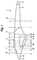
- Figure 1 is side plan view of a pointer according to an embodiment of this invention, this pointer simulating the shape of an airbrush, this illustration including a plurality of sectional lines therein.
- Figures 2(a) - 2(j) are cross-sectional views of the Figure 1 pointer, taken along the corresponding sectional lines illustrated in Figure 1.
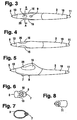
- Figure 3 is a top plan view of the pointer according to the Figure 1 embodiment of this invention.
- Figure 4 is a bottom plan view of the Figure 1-3 pointer.
- Figure 5 is a side plan view of the Figure 1 - 4 pointer, this figure illustrating the pointer in an upside down position in that the finger dial/wheel and switch button are typically positioned on the top side of the pointer during use.
- Figure 6 is a front plan view of the Figure 1 - 5 pointer illustrating the pointer from the tip portion thereof.
- Figure 7 is a cross-sectional view of the Figure 3 pointer, taken along the sectional line A-A of Figure 3.
- Figure 8 is a rear plan view of the Figure 1 - 7 pointer, illustrating the rear or eraser end of the pointer.
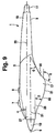
- Figure 9 is a side plan view of a pointer in accordance with the Figure 1 - 8 embodiment of this invention.
- Figure 1 is a side plan view of pointer 1 in accordance with an embodiment of this invention.
- Pointer 1 may be used in conjunction with known digitizer systems, including digitizer tablets. Manipulation of pointer 1 on or over a digitizer tablet enables a cursor to move in a corresponding manner on a corresponding computer display screen.
- Pointer 1 includes housing 3, pressure sensitive tip 5, finger dial/wheel 7, finger on/off clicking switch 9, eraser tip 11, front tip support 13, textured grip areas 15 disposed on both sides of the pointer, and grip area 17 which is larger than both tip support 13 and rear elongated portion 19 of the pointer.
- the pointer 1 is electronic in that electrical signals pass through circuitry therein.
- the pointer includes a tuning circuit therein (e.g. at least a capacitor and inductive coil), as disclosed in U.S. Patent No. 4,878,553.
- housing 3 may be a single injection molded plastic piece, or alternatively may be made up of a plurality of different and connected plastic pieces that are adhered or otherwise attached to one another.
- Tip 5 is pressure sensitive, in that by varying the amount of pressure applied to the tip against the corresponding digitizer writing tablet, the pen outputs a signal to the tablet that varies as a function of the pressure being applied to the tip.
- the tablet detects the different signals and can thus determine how much pressure is being applied to the tip.
- the tablet based upon signals received from the pointer can also determine the degree to which the finger dial is rotated from a predetermined position and whether the on/off switch is on or off.
- non-cylindrical grip portion 17 encompasses a much greater volume (and thus has a greater cross-section) than rear portion 19 and tip support 13.
- a cross-sectional portion of area 17, taken between the F and G sectional lines, defines an area more than twice as large as a select cross-section of tip support 13 taken in a similar cross-sectional manner. This is also the case with regard to cross-sectional areas of rear elongated portion 19 of pointer 1.
- tip support 13 may be integrally formed with housing 3, or alternatively of a separate material or separate piece.
- rotatable finger dial 7 is symmetrically located in the top center of housing 3 of pointer 1. This enables dial 7 to be easily manipulated by both right and left-handed users.
- Grip area 17 is symmetric about a longitudinal center line of the pointer as shown in Figures 2(a) - 2(c) and 2(h) - 2(j).
- grip area 17 is not symmetrical (i.e. non-symmetrical), as viewed in Figure 1, with respect to, for example, section line F-F. As shown, grip area 17 slopes downwardly to a greater degree on the eraser side of section line F-F, than on the tip 5 side of section line F-F. The most downward protruding point 21 (or apex) of grip area 17 is along section line G-G, and is located rearwardly of the symmetrical center of grip area 17 (approximately at section line F-F) as shown in Figure 1.
- grip area 17 flares outwardly (i.e. becomes wider) as it extends further towards the bottom of the pointer.
- grip area 17 is wider at the bottom thereof (e.g. proximate lowest point or apex 21) than it is at a central point 23 thereof.
- a recess 25 is provided on each side of pointer 1 proximate section line C-C.
- Recess 25 is shaped in order to minimize pressure points on a finger of the user, while simultaneously maximizing the amount of control that a user has on the position of pointer 1 on the corresponding digitizer tablet and the pressure applied to tip 5 on the tablet.
- a portion of recess 25, on each side of pointer 1, is located directly below a portion of dial 7, and proximate a front portion of a corresponding grip area 17.
- Grip area 17 is the portion which is enlarged relative to rear elongated portion 19 and front portion 27 of the pointer immediately behind tip support 13.
- Textured area 15 has a roughened surface texture relative to the remainder of housing 3. This texturing improves a user's ability to easily hold and control pointer 1.
- This texturing may be injection molded and integrally formed with housing 3, or alternatively may be rubberized.
- the entire grip area 17 may in some embodiments be textured/rubberized. Any suitable friction causing texture may be provided in area 15 on the surface of housing 3.
- Figure 9 is a side plan view of pointer 1, according to the same embodiment as shown in Figures 1 - 8.
- pointer 1 includes a tip or front center line or axis 31, as well as a rear center line or axis 33.
- Axis 31 extends through tip 5 of pointer 1.
- axis 33 extends through eraser 11 and thus the rear end of pointer 1.
- Axes 31 and 33 may be parallel to one another in certain embodiments of this invention, but this not need necessarily be the case. They may be slightly angled relative to one another in alternative embodiments. In either event, axes 31 and 33 are not co-axial, but rather, are spaced from one another and offset as illustrated in Figure 9.
- This offset between axis 31 and axis 33 enables tip 5 of pointer 1 to be positioned closer to the bottom portion of the pointer including recess 25 and grip area 17. Such positioning of the tip, at an elevation below the eraser as shown in Figure 1, makes it easier for a user to apply pressure to tip 5 on the corresponding tablet.
- grip area 17 includes two separate sloped portions 81 and 82. Sloped portion 81 sloped toward the apex 21 of the grip area 17 from the rear of the pointer 1, while sloped portion 82 slopes toward the apex of the grip area from the front/tip of the pointer. As illustrated, slope 82, at one location thereon, slopes toward apex 21 so as to define an angle ⁇ relative to a plane parallel to axis 31. Thus, angles ⁇ may also be said to be the angle which surface portion 82 slopes relative to axis 31. In certain embodiments of this invention, portion 82 slopes at an angle ⁇ of from about 20-45 degrees, more preferably from about 25-40 degrees.
- Fig. 9 Also shown in Fig. 9 is surface portion 81 sloping at one part thereof at an angle ⁇ relative to axis 33 and axis (or a plane parallel to axes 31 and 33), and at another part thereof at an angle ⁇ relative to axes 31 and 33 (or a plane parallel to these axes).
- angle ⁇ is from about 35-70 degrees (more preferably from about 30-50 degrees)
- angle ⁇ is from about 110-135 degrees (more preferably from about 115-125 degrees).
- surfaces 81 and 82 each vary with regard to slope, and the aforesaid angles only represent portions of these surfaces. In certain embodiments, substantial portions of surfaces 81 and 82 are sloped at the aforesaid angles.
- the portion immediately behind and adjacent tip support 13 slopes upwardly away from the tip at an angle ⁇ of from about 15-30 degrees relative to axes 31 and 33.
Landscapes
- Engineering & Computer Science (AREA)
- Theoretical Computer Science (AREA)
- General Engineering & Computer Science (AREA)
- Physics & Mathematics (AREA)
- General Physics & Mathematics (AREA)
- Human Computer Interaction (AREA)
- Artificial Intelligence (AREA)
- Computer Hardware Design (AREA)
- Computer Vision & Pattern Recognition (AREA)
- Position Input By Displaying (AREA)
Claims (8)
- Un pointeur digilisateur (1) pour être utilisé avec un système digilisateur; le pointeur digilisateur comprenant :où ledit boítier (3) définit une surface extérieure incluant une partie (19) arrière allongée et une zone de prise (17) qui est située entre la partie (19) arrière allongée et la pointe (5) ; une section transversale choisie de ladite zone de prise (17) définissant une zone essentiellement plus grande qu'une section transversale choisie de ladite partie (19) arrière et essentiellement plus grande qu'une section transversale choisie de ladite pointe (5) ainsi qu'une part essentielle de ladite zone de prise (17) qui se trouvant située entre ledit centre du pointeur (1) et la pointe (5), caractérisé en ce que la zone de prise (17) définit sur la partie inférieure du boítier (3), opposée à la molette de réglage (7) et / ou le commutateur (9), un sommet (21), lequel sommet est défini comme la partie de la zone de prise (17) positionnée plus loin d'un premier axe (31) du pointeur (1) s'étendant à travers la pointe (5), où une première inclinaison (82) sur un premier côté dudit sommet (21) et une seconde inclinaison (81) sur un second côté dudit sommet (21) ne sont pas symétriques par rapport audit sommet (21) en ce que la première et la seconde inclinaison (82, 81) sont formées différemment lorsqu'elles s'écartent dans des directions opposées dudit apex (21 ).un boítier (3);une pointe (5) dans laquelle un centre du pointeur (1) est situé à une distance égale entre ladite pointe (5) et une extrémité arrière du pointeur (1) ; etune molette de réglage (7) et / ou un commentateur (9) situés dans le centre supérieur du boítier (3);
- Le pointeur selon la revendication 1, caractérisé en ce que le pointeur comprend un second axe (33) approximativement parallèle au premier axe (31); ledit second axe (33) s'étendant à travers l'extrémité arrière ( 11 ) du pointeur (1), où ledit premier axe (31 ) et ledit second axe (33) sont décalés l'un par rapport à l'autre.
- Le pointeur selon la revendication 1 ou 2, caractérisé en ce que la première inclinaison (82) et la seconde inclinaison (81) sont inclinées dans des directions opposées dudit apex (21) dans des directions différentes.
- Le pointeur selon la revendication 3, caractérisé en que la première inclinaison (82) est inclinée vers ladite pointe (5) du pointeur (5) et où au moins une partie d'une surface de ladite première inclinaison (82) définit une inclinaison β d'environ 20 à 45 degrés par rapport audit premier axe (31) du pointeur.
- Le pointeur selon la revendication 3 ou 4, caractérisé en ce que la seconde inclinaison (81 ) est inclinée vers l'extrémité arrière du pointeur (1), où une première partie d'une surface de ladite seconde inclinaison (81) définit un angle d'inclinaison d'environ 35 à 70 degrés par rapport au second axe (33) du pointeur (1 ).
- Le pointeur selon n'importe laquelle des revendications précédentes, caractérisé en ce que la partie située entre la tête (5) et un commutateur (9) est inclinée vers le haut selon un angle α d'environ 15 à 30 degrés par rapport au premier axe (31).
- Le pointeur selon n'importe laquelle des revendications précédentes, où le boítier (3) au sommet (21) de la zone de prise (17) est plus large qu'une largeur du boítier (3) dans la zone de prise (17) à un endroit situé plus près du premier axe (31).
- Le pointeur selon n'importe laquelle des revendications précédentes, caractérisé en ce que la zone de prise (17) inclus une partie de prise qui comprend une texture de surface ou un élément caoutchouté pour améliorer les caractéristiques de prise.
Applications Claiming Priority (2)
| Application Number | Priority Date | Filing Date | Title |
|---|---|---|---|
| US09/110,071 US6512513B2 (en) | 1919-04-01 | 1998-07-02 | Pointer for use in digitizer systems |
| US110071 | 1998-07-02 |
Publications (3)
| Publication Number | Publication Date |
|---|---|
| EP0969404A2 EP0969404A2 (fr) | 2000-01-05 |
| EP0969404A3 EP0969404A3 (fr) | 2002-03-27 |
| EP0969404B1 true EP0969404B1 (fr) | 2003-12-10 |
Family
ID=22331080
Family Applications (1)
| Application Number | Title | Priority Date | Filing Date |
|---|---|---|---|
| EP99109662A Expired - Lifetime EP0969404B1 (fr) | 1998-07-02 | 1999-05-15 | Pointeur à crayon utilisé dans un système digilisateur |
Country Status (7)
| Country | Link |
|---|---|
| US (1) | US6512513B2 (fr) |
| EP (1) | EP0969404B1 (fr) |
| JP (1) | JP2000056913A (fr) |
| KR (1) | KR100600528B1 (fr) |
| CN (1) | CN1229239C (fr) |
| DE (1) | DE69913440T2 (fr) |
| TW (1) | TW434515B (fr) |
Families Citing this family (21)
| Publication number | Priority date | Publication date | Assignee | Title |
|---|---|---|---|---|
| US6803906B1 (en) * | 2000-07-05 | 2004-10-12 | Smart Technologies, Inc. | Passive touch system and method of detecting user input |
| US7532206B2 (en) * | 2003-03-11 | 2009-05-12 | Smart Technologies Ulc | System and method for differentiating between pointers used to contact touch surface |
| US7411575B2 (en) * | 2003-09-16 | 2008-08-12 | Smart Technologies Ulc | Gesture recognition method and touch system incorporating the same |
| US7274356B2 (en) * | 2003-10-09 | 2007-09-25 | Smart Technologies Inc. | Apparatus for determining the location of a pointer within a region of interest |
| US7262906B2 (en) * | 2004-03-26 | 2007-08-28 | Leica Microsystems Cms Gmbh | Means for transporting a microscope |
| US7460110B2 (en) | 2004-04-29 | 2008-12-02 | Smart Technologies Ulc | Dual mode touch system |
| EP2840465A3 (fr) * | 2005-01-30 | 2015-08-26 | Swiftpoint Limited | Périphérique souris d'ordinateur |
| JP2007072555A (ja) * | 2005-09-05 | 2007-03-22 | Sony Corp | 入力ペン |
| US20080094375A1 (en) * | 2006-10-18 | 2008-04-24 | Jerry Craig | Universal flat horizontal use stylus |
| US9442607B2 (en) | 2006-12-04 | 2016-09-13 | Smart Technologies Inc. | Interactive input system and method |
| CN101689355A (zh) * | 2007-06-15 | 2010-03-31 | 路迪亚公司 | 大平板显示器中的交互性 |
| US8902193B2 (en) | 2008-05-09 | 2014-12-02 | Smart Technologies Ulc | Interactive input system and bezel therefor |
| US8339378B2 (en) | 2008-11-05 | 2012-12-25 | Smart Technologies Ulc | Interactive input system with multi-angle reflector |
| USD621403S1 (en) * | 2009-05-10 | 2010-08-10 | Sabatino Agnitti | Infrared pen |
| TWI397002B (zh) * | 2009-05-22 | 2013-05-21 | Waltop Int Corp | 電磁筆 |
| US9870093B2 (en) | 2010-11-23 | 2018-01-16 | Ge Aviation Systems Llc | System and method for improving touch screen display use under vibration and turbulence |
| CN102416104A (zh) * | 2011-12-10 | 2012-04-18 | 闫位国 | 一种养生保健的药物及其制备方法 |
| US9600053B2 (en) * | 2013-03-11 | 2017-03-21 | Barnes & Noble College Booksellers, Llc | Stylus control feature for locking/unlocking touch sensitive devices |
| CN104118242B (zh) * | 2014-05-30 | 2017-04-26 | 刘保伸 | 笔具握持结构 |
| US10073544B2 (en) | 2015-10-14 | 2018-09-11 | Microsoft Technology Licensing, Llc | Stylus with adjustable grip diameter |
| US10185409B2 (en) | 2016-03-15 | 2019-01-22 | Microsoft Technology Licensing, Llc | Stylus with an adjustable dimension |
Family Cites Families (17)
| Publication number | Priority date | Publication date | Assignee | Title |
|---|---|---|---|---|
| US6259438B1 (en) * | 1998-06-04 | 2001-07-10 | Wacom Co., Ltd. | Coordinate input stylus |
| DE2729749A1 (de) * | 1977-07-01 | 1979-01-11 | Juergen Berger | Griffausbildung an einem schreibgriffel oder einem werkzeug |
| DE3406522A1 (de) * | 1984-02-11 | 1985-09-12 | Pelikan Ag, 3000 Hannover | Gehaeuse fuer von hand gehaltene geraete, insbesondere schreibgeraete |
| US4823294A (en) * | 1986-08-28 | 1989-04-18 | Rouhani S Zia | Single-hand computer keyboard |
| JPS6370326A (ja) | 1986-09-12 | 1988-03-30 | Wacom Co Ltd | 位置検出装置 |
| US4707571A (en) * | 1986-10-29 | 1987-11-17 | Hewlett-Packard Company | Ergonomic digitizer stylus |
| US5251123A (en) * | 1987-10-19 | 1993-10-05 | I C Operating, Inc. | High resolution system for sensing spatial coordinates |
| US5014044A (en) | 1988-05-27 | 1991-05-07 | Summagraphics Corporation | Magnification assembly for digitizer cursor |
| US5109141A (en) | 1989-11-13 | 1992-04-28 | Summagraphics Corporation | Digitizer stylus with z-axis side control |
| US5055831A (en) | 1989-10-06 | 1991-10-08 | Summagraphics Corporation | Cursor for digitizer tablet |
| US5061828A (en) | 1989-11-13 | 1991-10-29 | Summagraphics Corporation | Digitizer stylus with Z-axis side pressure control |
| US5004871A (en) | 1989-11-13 | 1991-04-02 | Summagraphics Corporation | Digitizer stylus having side switch |
| DE9201555U1 (de) * | 1992-02-08 | 1992-04-30 | Schroll, Stefan, Dipl.-Ing. (FH), 8221 Nußdorf | Schreibstift |
| US5654529A (en) * | 1995-05-03 | 1997-08-05 | Hewlett-Packard Company | Stylus-input computing system with erasure |
| JP3192349B2 (ja) * | 1995-06-19 | 2001-07-23 | シャープ株式会社 | タッチ入力ペン |
| JPH10133805A (ja) * | 1996-10-31 | 1998-05-22 | Wacom Co Ltd | 位置指示器 |
| USD417206S (en) | 1998-08-05 | 1999-11-30 | Wacom Co., Ltd. | Digitizer stylus |
-
1998
- 1998-07-02 US US09/110,071 patent/US6512513B2/en not_active Expired - Fee Related
-
1999
- 1999-05-15 DE DE69913440T patent/DE69913440T2/de not_active Expired - Fee Related
- 1999-05-15 EP EP99109662A patent/EP0969404B1/fr not_active Expired - Lifetime
- 1999-06-11 CN CNB991084209A patent/CN1229239C/zh not_active Expired - Fee Related
- 1999-06-14 TW TW088109889A patent/TW434515B/zh not_active IP Right Cessation
- 1999-06-28 KR KR1019990024852A patent/KR100600528B1/ko not_active Expired - Fee Related
- 1999-06-28 JP JP11181621A patent/JP2000056913A/ja active Pending
Also Published As
| Publication number | Publication date |
|---|---|
| JP2000056913A (ja) | 2000-02-25 |
| KR20000011340A (ko) | 2000-02-25 |
| DE69913440D1 (de) | 2004-01-22 |
| EP0969404A3 (fr) | 2002-03-27 |
| US6512513B2 (en) | 2003-01-28 |
| DE69913440T2 (de) | 2004-10-21 |
| CN1229239C (zh) | 2005-11-30 |
| US20010043185A1 (en) | 2001-11-22 |
| KR100600528B1 (ko) | 2006-07-13 |
| EP0969404A2 (fr) | 2000-01-05 |
| CN1240720A (zh) | 2000-01-12 |
| TW434515B (en) | 2001-05-16 |
Similar Documents
| Publication | Publication Date | Title |
|---|---|---|
| US20010043185A1 (en) | Pointer for use in digitizer systems | |
| EP0567215B1 (fr) | Système de codage de position | |
| US6972749B2 (en) | Touch-sensitive device for scrolling a document on a display | |
| EP0964355B1 (fr) | Dispositif d'entrée de coordonnées pouvant être utilisé avec la main gauche ou la main droite | |
| US7333086B2 (en) | Dual mode computer mouse | |
| US20160109967A1 (en) | Stylus | |
| US5717435A (en) | Side switch mechanism, and stylus pen using the same | |
| US6046728A (en) | Keyboard actuated pointing device | |
| US6480183B1 (en) | Digital joystick using capacitive sensor | |
| US20040046734A1 (en) | Thumb-retained stylus | |
| JP2005293606A (ja) | タッチ入力検知方法及びタッチ入力検知装置 | |
| WO2004021324A2 (fr) | Procede et dispositif de dispositif de pointage hybride pour systeme de traitement de donnees | |
| US20060001646A1 (en) | Finger worn and operated input device | |
| US20040222965A1 (en) | System and method for generating an analog signal in a hand-held computing device | |
| KR20170016587A (ko) | 터치 입력장치 및 이를 포함하는 차량 | |
| US7570247B2 (en) | Modular assembly for a self-indexing computer pointing device | |
| US20040201577A1 (en) | Input element and a method for making an input to a touch-pad | |
| EP0266189B1 (fr) | Crayon digital | |
| JPH10171580A (ja) | 静電容量型座標入力パッド用入力ペン | |
| EP0967540A3 (fr) | Systéme numeriseur avec la capacité de changer la forme d'un curseur | |
| US11966520B1 (en) | Ambidextrous mouse | |
| US20080316172A1 (en) | Manual input device | |
| US20030098849A1 (en) | Double roller mouse structure | |
| KR200201663Y1 (ko) | 펜형 볼 마우스 | |
| JPH07225646A (ja) | 位置入力用スタイラス |
Legal Events
| Date | Code | Title | Description |
|---|---|---|---|
| PUAI | Public reference made under article 153(3) epc to a published international application that has entered the european phase |
Free format text: ORIGINAL CODE: 0009012 |
|
| AK | Designated contracting states |
Kind code of ref document: A2 Designated state(s): AT BE CH CY DE DK ES FI FR GB GR IE IT LI LU MC NL PT SE |
|
| AX | Request for extension of the european patent |
Free format text: AL;LT;LV;MK;RO;SI |
|
| PUAL | Search report despatched |
Free format text: ORIGINAL CODE: 0009013 |
|
| AK | Designated contracting states |
Kind code of ref document: A3 Designated state(s): AT BE CH CY DE DK ES FI FR GB GR IE IT LI LU MC NL PT SE |
|
| AX | Request for extension of the european patent |
Free format text: AL;LT;LV;MK;RO;SI |
|
| RIC1 | Information provided on ipc code assigned before grant |
Free format text: 7G 06K 11/18 A, 7B 43K 23/008 B |
|
| AKX | Designation fees paid | ||
| 17P | Request for examination filed |
Effective date: 20020809 |
|
| RBV | Designated contracting states (corrected) |
Designated state(s): AT BE |
|
| RBV | Designated contracting states (corrected) |
Designated state(s): DE GB |
|
| 17Q | First examination report despatched |
Effective date: 20030116 |
|
| GRAH | Despatch of communication of intention to grant a patent |
Free format text: ORIGINAL CODE: EPIDOS IGRA |
|
| GRAS | Grant fee paid |
Free format text: ORIGINAL CODE: EPIDOSNIGR3 |
|
| GRAA | (expected) grant |
Free format text: ORIGINAL CODE: 0009210 |
|
| AK | Designated contracting states |
Kind code of ref document: B1 Designated state(s): DE GB |
|
| REG | Reference to a national code |
Ref country code: GB Ref legal event code: FG4D |
|
| REG | Reference to a national code |
Ref country code: IE Ref legal event code: FG4D |
|
| REF | Corresponds to: |
Ref document number: 69913440 Country of ref document: DE Date of ref document: 20040122 Kind code of ref document: P |
|
| PLBE | No opposition filed within time limit |
Free format text: ORIGINAL CODE: 0009261 |
|
| STAA | Information on the status of an ep patent application or granted ep patent |
Free format text: STATUS: NO OPPOSITION FILED WITHIN TIME LIMIT |
|
| 26N | No opposition filed |
Effective date: 20040913 |
|
| REG | Reference to a national code |
Ref country code: IE Ref legal event code: MM4A |
|
| PGFP | Annual fee paid to national office [announced via postgrant information from national office to epo] |
Ref country code: DE Payment date: 20080325 Year of fee payment: 10 |
|
| PGFP | Annual fee paid to national office [announced via postgrant information from national office to epo] |
Ref country code: GB Payment date: 20080522 Year of fee payment: 10 |
|
| GBPC | Gb: european patent ceased through non-payment of renewal fee |
Effective date: 20090515 |
|
| PG25 | Lapsed in a contracting state [announced via postgrant information from national office to epo] |
Ref country code: GB Free format text: LAPSE BECAUSE OF NON-PAYMENT OF DUE FEES Effective date: 20090515 |
|
| PG25 | Lapsed in a contracting state [announced via postgrant information from national office to epo] |
Ref country code: DE Free format text: LAPSE BECAUSE OF NON-PAYMENT OF DUE FEES Effective date: 20091201 |