EP0969505A2 - SOI Substrat - Google Patents
SOI Substrat Download PDFInfo
- Publication number
- EP0969505A2 EP0969505A2 EP99110019A EP99110019A EP0969505A2 EP 0969505 A2 EP0969505 A2 EP 0969505A2 EP 99110019 A EP99110019 A EP 99110019A EP 99110019 A EP99110019 A EP 99110019A EP 0969505 A2 EP0969505 A2 EP 0969505A2
- Authority
- EP
- European Patent Office
- Prior art keywords
- wafer
- single crystal
- silicon
- nitrogen
- soi substrate
- Prior art date
- Legal status (The legal status is an assumption and is not a legal conclusion. Google has not performed a legal analysis and makes no representation as to the accuracy of the status listed.)
- Ceased
Links
Images
Classifications
-
- H—ELECTRICITY
- H10—SEMICONDUCTOR DEVICES; ELECTRIC SOLID-STATE DEVICES NOT OTHERWISE PROVIDED FOR
- H10P—GENERIC PROCESSES OR APPARATUS FOR THE MANUFACTURE OR TREATMENT OF DEVICES COVERED BY CLASS H10
- H10P14/00—Formation of materials, e.g. in the shape of layers or pillars
- H10P14/20—Formation of materials, e.g. in the shape of layers or pillars of semiconductor materials
-
- H—ELECTRICITY
- H10—SEMICONDUCTOR DEVICES; ELECTRIC SOLID-STATE DEVICES NOT OTHERWISE PROVIDED FOR
- H10P—GENERIC PROCESSES OR APPARATUS FOR THE MANUFACTURE OR TREATMENT OF DEVICES COVERED BY CLASS H10
- H10P90/00—Preparation of wafers not covered by a single main group of this subclass, e.g. wafer reinforcement
- H10P90/19—Preparing inhomogeneous wafers
- H10P90/1904—Preparing vertically inhomogeneous wafers
- H10P90/1906—Preparing SOI wafers
- H10P90/1914—Preparing SOI wafers using bonding
-
- H—ELECTRICITY
- H10—SEMICONDUCTOR DEVICES; ELECTRIC SOLID-STATE DEVICES NOT OTHERWISE PROVIDED FOR
- H10W—GENERIC PACKAGES, INTERCONNECTIONS, CONNECTORS OR OTHER CONSTRUCTIONAL DETAILS OF DEVICES COVERED BY CLASS H10
- H10W10/00—Isolation regions in semiconductor bodies between components of integrated devices
- H10W10/10—Isolation regions comprising dielectric materials
- H10W10/181—Semiconductor-on-insulator [SOI] isolation regions, e.g. buried oxide regions of SOI wafers
Definitions
- the present invention relates to a method for producing a bonded SOI substrate utilizing a silicon single crystal wafer produced by the Czochralski method (referred to as the "CZ method” hereinafter), and a bonded SOI substrate.
- the present invention relates to a method for producing a thin film SOI substrate having an SOI layer thickness of 1 ⁇ m or less, wherein the size of crystal defects called grown-in defects in the SOI layer is made smaller, and therefore the defects can be easily eliminated by means of heat treatment, and an SOI substrate produced by the method.
- a bonded substrate whose bonding strength has been enhanced by a heat treatment can subsequently be processed by, for example, grinding, polishing or the like, either one of the wafers can be made thinner to a desired thickness by grinding, polishing or the like to afford an SOI layer on which devices are formed.
- the produced SOI substrate contains bulk crystals of the silicon single crystal wafer exhibiting excellent crystallinity as they are, the obtained SOI layer would exhibit excellent crystallinity, and this characteristic is more advantageous compared with other SOI production methods such as the SIMOX (Separation by Implanted Oxygen) method and the fusion recrystallization method.
- SIMOX Separatation by Implanted Oxygen
- silicon single crystal wafers those silicon single crystal wafers obtained by slicing a single crystal ingot grown by the Czochralski method (CZ method) have been mainly used.
- the major cause of these pits is considered to be clusters of vacancies, which aggregate during the production of single crystals, or oxide precipitates, which are aggregates of oxygen atoms contaminated from quartz crucibles. Because these crystal defects present in regions where devices are to be formed may become harmful defects that degrade device characteristics, various kinds of methods for decreasing such crystal defects have been investigated.
- the crystals may be grown at an extremely low growth rate (for example, 0.4 mm/min or less). See Japanese Patent Application Laid-open (KOKAI) No. 2-267195.
- KKAI Japanese Patent Application Laid-open
- this method generates crystal defects that are considered dislocation loops formed by newly gathered excessive interstitial silicon, and they markedly degrade the device characteristics, which means that the method cannot be a solution of the problem.
- such a decrease of crystal growth rate from the conventional 1 mm/min or more to 0.4 mm/min or less invites marked decrease of the productivity and increase of the cost of single crystals.
- the produced SOI layer of course contains crystal defects, and they degrade the electric characteristics of the SOI layer such as oxide dielectric breakdown voltage.
- the substrate is a thin film SOI substrate, i.e., the SOI layer to be formed must have a thickness of, for example, 1 ⁇ m or less, the crystal defects may be present in such a manner that they penetrate the SOI layer and thus form pin holes, which markedly degrade the quality and the characteristics.
- the present invention has been accomplished in view of the aforementioned problems, and its object is to provide a method for producing SOI substrates, in particular, thin film SOI substrates having an SOI layer thickness of 1 ⁇ m or less, wherein crystal defects in the SOI layer can be made smaller in their size, and easily eliminated by a heat treatment, and such SOI substrates with low cost and high productivity.
- the present invention provides a method for producing an SOI substrate comprising forming an oxide layer on a surface of at least one silicon wafer among two silicon wafers, closely contacting one wafer with the other wafer so that the oxide layer should be interposed between them, subjecting the wafers to a heat treatment to firmly bond the wafers, and making a device processing (fabricating) side wafer thinner to a desired thickness, wherein a silicon single crystal wafer obtained by growing a silicon single crystal ingot doped with nitrogen by the Czochralski method, and slicing the single crystal ingot into a silicon single crystal wafer is used as the device processing side wafer.
- an SOI substrate having an SOI layer with an extremely small crystal defect size can be obtained. Therefore, the crystal defects can be easily eliminated by subjecting the SOI substrate to a heat treatment, and quality of devices formed on the SOI layer such as electric characteristics can be markedly improved.
- the nitrogen in the device processing side wafer to be the SOI layer is out-diffused during the heat treatment, it does not harmfully affect on devices to be formed.
- the present invention also provides a method for producing an SOI substrate comprising closely contacting a silicon wafer and an insulator substrate, subjecting them to a heat treatment to firmly bond them, and making the silicon wafer that is a device processing side wafer thinner to a desired thickness, wherein a silicon single crystal wafer obtained by growing a silicon single crystal ingot doped with nitrogen by the Czochralski method, and slicing the single crystal ingot into a silicon single crystal wafer is used as the silicon wafer that is the device processing side wafer.
- a silicon single crystal wafer doped with nitrogen may be used as the device processing side wafer. Also in this case, the crystal defect size in the SOI layer can be made extremely small, and the productivity of silicon wafers can be improved.
- concentration of nitrogen doped into the single crystal ingot is preferably controlled to be in the range of 1 ⁇ 10 10 to 5 ⁇ 10 15 atoms/cm 3 .
- the nitrogen concentration is preferably 1 ⁇ 10 10 or more in order to sufficiently suppresses the growth of crystal defects and surely reduce the generation of pin holes in the SOI layer, and the nitrogen concentration is preferably 5 ⁇ 10 15 atoms/cm 3 or less in order not to inhibit the crystallization of silicon single crystals.
- concentration of oxygen contained in the single crystal ingot is preferably controlled to be 1.2 ⁇ 10 18 atoms/cm 3 or less (value according to ASTM '79).
- the heat treatment for obtaining firm bonding may be performed at a temperature of 900°C or more.
- the two pieces of wafers can be bonded with sufficient strength, and the nitrogen can be surely eliminated from the region to be the SOI layer of device processing side wafer. Therefore, when it functions in an SOI substrate, nitrogen no longer harmfully affects on the electric characteristics or the like.
- the heat treatment at a temperature in such a range affords a region free from defects due to oxygen in a region to be the SOI layer of the device processing side wafer, reduced defects and prevention of degradation of electric characteristics of the SOI layer due to oxygen and the like can be achieved.
- the device processing side wafer may be made thinner to a thickness of 1 ⁇ m or less.
- pin holes are particularly likely to be formed in an extremely thin SOI layer such as one having a thickness of 1 ⁇ m or less due to the penetration of crystal defects, use of the silicon wafer doped with nitrogen according to the present invention is advantageous for such a substrate.
- the heat treatment may be preformed at a temperature of 900°C or more.
- the crystal defects having a small size in the SOI layer can easily be eliminated.
- an SOI substrate produced by the production method of the present invention would have crystal defects of an extremely small size in the SOI layer, and they can easily be eliminated by the heat treatment. Therefore, the SOI substrate of the present invention would have few crystal defects.
- the SOI substrate of the present invention is, for example, an SOI substrate which is produced by forming an oxide layer on a surface of at least one silicon wafer among two silicon wafers, closely contacting one silicon wafer with the other silicon wafer so that the oxide layer should be interposed between them, subjecting the waters to a heat treatment to firmly bond the wafers, and making a device processing side wafer thinner to a desired thickness, wherein the device processing side wafer is a silicon single crystal wafer obtained by growing a silicon single crystal ingot doped with nitrogen by the Czochralski method, and slicing the single crystal ingot into a silicon single crystal wafer.
- the SOI substrate of the present invention may also be an SOI substrate which is produced by closely contacting a silicon wafer with an insulator substrate, subjecting them to a heat treatment to firmly bond them, and making the silicon wafer that is a device processing side wafer thinner to a desired thickness, wherein the silicon wafer that is the device processing side wafer is a silicon single crystal wafer obtained by growing a silicon single crystal ingot doped with nitrogen by the Czochralski method, and slicing the single crystal ingot into a silicon single crystal wafer.
- the nitrogen concentration in the device processing side wafer may be in the range of 1 ⁇ 10 10 to 5 ⁇ 10 15 atoms/cm 3 , and the oxygen concentration in the device processing side wafer may be 1.2 ⁇ 10 18 atoms/cm 3 or less.
- the SOI substrate of the present invention can be an SOI substrate having an SOI layer of good quality containing particularly few pin holes.
- SOI substrates exhibiting a small crystal defect size in the SOI layer and having few pin holes can be obtained with high productivity and low cost by producing the SOI substrates with silicon single crystal wafers doped with nitrogen.
- the method of the present invention is particularly effective as a method for producing thin film SOI substrates having an SOI layer thickness of 1 ⁇ m or less, in which the crystal defects and the pin holes in the SOI layer may be particularly likely to constitute problems.
- penetrating pin holes are reduced, not by eliminating crystal defects in the produced SOI layer, but by making the crystal defect size in the material silicon wafers smaller so that the defects should become likely to be eliminated by a heat treatment.
- the present invention has been accomplished based on the finding that, if a silicon single crystal wafer which has been produced by using a technique that makes the crystal defect size smaller through doping of silicon single crystal with nitrogen during its growth by the CZ method is used for a bonded SOI substrate, an SOI substrate which has an SOI layer exhibiting a small crystal defect size in the SOI layer, therefore, containing few penetrating pin holes and defects more likely to be eliminated by a heat treatment can be obtained with low cost and high productivity, and further based on investigation of various conditions therefor.
- wafers doped with nitrogen are used as material wafers of bonded SOI substrates.
- bonded SOI substrates two pieces of wafers are closely contacted and then subjected to a heat treatment for bonding, and therefore the nitrogen is out-diffused by the heat treatment, and does not remain in the SOI layer.
- the SOI layer is produced by utilizing the nitrogen-doped substrate, the size of the grown-in defect remains small even though the nitrogen is out-diffused.
- the defects due to oxygen are unlikely to be formed around the bonding interface, while its reason is not clear. Therefore, the density of defects due to oxygen also becomes extremely low in the region to be the SOI layer.
- silicon single crystal wafers doped with nitrogen are first produced by growing a silicon single crystal ingot doped with nitrogen by the CZ method, and slicing the single crystal ingot.
- the pulled crystal in the CZ method, which comprises bringing a seed crystal into contact with starting polycrystal silicon melt contained in a quartz crucible, and slowly pulling the seed crystal with rotation to grow a silicon single crystal ingot of a desired diameter, the pulled crystal can be doped with nitrogen by introducing a nitride into the quartz crucible beforehand, or adding a nitride into the melt, or employing an atmosphere containing nitrogen as the atmospheric gas.
- the doping amount in the crystal can be controlled by adjusting the amount of nitride, concentration of nitrogen gas, introduction time thereof and the like.
- the concentration of the doped nitrogen is preferably at a level sufficiently causing formation of heterogeneous nuclei, i.e., 1 ⁇ 10 10 atoms/cm 3 or more, more preferably 5 ⁇ 10 13 atoms/cm 3 or more. Such a concentration sufficiently suppresses the growth of crystal defects.
- the nitrogen concentration exceeds 5 ⁇ 10 15 atoms/cm 3 , which is the solid solubility in silicon single crystal, crystallization of silicon single crystal itself is inhibited, and hence the nitrogen concentration is selected so that it should not exceed the aforementioned value.
- concentration of oxygen contained in the single crystal ingot is preferably controlled to be 1.2 ⁇ 10 18 atoms/cm 3 or less.
- Such low oxygen content in silicon single crystals can, together with the contained nitrogen, further suppress the formation of crystal defects, and suppress the formation of the aforementioned OSF. This makes it possible to further reduce crystal defects in the SOI layer.
- the contained oxygen concentration can be lowered to the aforementioned range by a conventional method.
- an oxygen concentration in the aforementioned range can be readily obtained by means of decreasing crucible rotation speed, increasing introduced gas flow, reducing atmospheric pressure, control of temperature distribution and convection of silicon melt, and the like.
- a silicon single crystal ingot doped with nitrogen at a desired concentration and containing oxygen at a desired concentration can be obtained by the CZ method.
- Such an ingot can be sliced by a cutting machine such as inner diameter slicer or wire saw, and processed into a silicon single crystal wafer through various process steps such as chamfering, lapping, etching, and polishing in conventional manners.
- process steps such as chamfering, lapping, etching, and polishing in conventional manners.
- these steps are merely exemplary steps, and there can be various other steps such as cleaning.
- the steps may also be used in a suitably modified manner such as alteration of the step sequence and omission of some steps depending on the purpose.
- a bonded SOI substrate is produced by using the above-obtained silicon single crystal wafer at least as the device processing side wafer.
- the method for producing the SOI substrate of the present invention will be explained by exemplifying a case where two pieces of silicon wafers are bonded with reference to the drawing.
- the present invention is not limited to the following explanation.
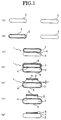
- Fig. 1 illustrates exemplary process steps for producing the bonded SOI substrate of the present invention.
- Fig. 1 there are first provided the material wafers for producing an SOI substrate by bonding, a bond wafer 2 (device processing side wafer) and a base wafer 3 (Fig. 1(a)).
- the silicon single crystal wafer doped with nitrogen by the CZ method as described above is used at least as the bond wafer 2, which is a device processing side wafer.
- the bond wafer 2 which is a device processing side wafer.
- both of the two wafers may be those doped with nitrogen.
- the bond wafer 2 is subjected to a heat treatment to form an oxide layer 4 on the bond wafer surface (Fig. 1(b)).
- This heat treatment is performed at a high temperature, for example, 1000°C or more, and the doped nitrogen is out-diffused during this treatment.
- the SOI layer does not contain nitrogen after it has been made thinner, and the produced devices are not harmfully affected.
- the oxide layer may be formed on the base wafer 3, or on the both wafers.
- nitrogen in the bond wafer 2 will be out-diffused during a subsequent step, i.e., the heat treatment for bonding.
- the bond wafer 2 on which the oxide layer has been formed and the base wafer 3 are closely contacted with each other in a clean atmosphere (Fig. 1(c)).
- the bond wafer 2 and the base wafer 3 are firmly bonded by subjecting them to a heat treatment in an oxidizing atmosphere to form a bonded substrate 1.
- the bond wafer 2 and the base wafer 3 are firmly bonded, and an oxide film 5, which becomes an etching prevention film in a subsequent step, is formed on the whole external surface of the bonded substrate 1 (Fig. 1(d)).
- the heat treatment may be performed, for example, at a temperature in the range of 200 to 1200°C, preferably at a temperature of 900°C or more, in an atmosphere containing oxygen or steam.
- the above temperature range is defined because the heat treatment at a temperature in such a high temperature range can realize the bonding of the two wafers with sufficient strength, and surely out-diffuse nitrogen from the device processing side wafer.
- the size of the grown-in defects contained in nitrogen-doped substrates is advantageously reduced, and harmful effects of nitrogen on electric characteristics of devices can completely be eliminated because the nitrogen has been out-diffused.
- harmful effects of oxygen are also eliminated because defects due to oxygen are unlikely to be formed around the bonding interface.
- the bonded substrate 1 bonded as described above comprises unbonded portions of the bond wafer 2 and the base wafer 3 having a width of about 2 mm from the external periphery. Because such unbonded portions cannot be used as the SOI layer on which devices are formed, and in addition they may be delaminated in a subsequent step to cause various problems, they must be removed.
- an external periphery portion of the bond wafer 2 including the unbonded portion is first removed by grinding it to a predetermined thickness t as shown in Fig. 1(e). Grinding is preferred because it can realize rapid removal and good processing precision.
- the predetermined thickness t is preferably made smaller as far as possible, because a smaller thickness t affords a thinner stock removal to be removed in the subsequent etching step.
- the unbonded portion at the periphery of the bond wafer 2 is completely removed by etching as shown in Fig. 1(f).
- This can be easily performed by immersing the bonded substrate 1 in an etching solution showing much larger etching rate as to silicon single crystal compared with the etching rate as to the oxide film. That is, the periphery of the bond wafer 2 is etched by the etching solution because silicon has been exposed by the grinding, whilst the other part of the surface of the bonded substrate 1 is not etched because it is covered with the oxide film 5.
- the etching may be the so-called alkali etching with KOH, NaOH and the like.
- the unbonded portion present at the periphery of the bonded substrate 1 can be completely removed by etching in a short period of time.
- the bond wafer 2 can be made thinner from its surface to a desired thickness by grinding, polishing or the like in a usual manner to prepare a bonded SOI substrate having an SOI layer 6 as shown in Fig. 1(g).
- the method of the present invention is particularly advantageous when the SOI layer is made thinner to a thickness of 1 ⁇ m or less, because such a thin layer is likely to be penetrated by the crystal defects and hence suffer from pin holes.
- the present invention is not limited to the above explanation, and the bond wafer may be made thinner by any means that can make it thinner.
- the present invention is of course effective also for the case where the wafer is made thinner by the vapor phase etching, or the method where the wafers are implanted with ions, bonded together, and then delaminated, which are recently attracting attentions as techniques for producing an extremely thin SOI layer.
- the vapor phase etching is one of the so-called dry etching methods, and it comprises, for example, determining thickness distribution of SOI layer on an SOI substrate, and running a cavity retaining plasma on the SOI substrate according to the layer thickness distribution. That is, the time for exposing the surface of the SOI layer to the plasma is controlled by the running speed, which is controlled according to the layer thickness distribution. As a result, the amount removed by etching is controlled to afford a uniform thickness of the SOI layer on the SOI substrate.
- the method for producing an SOI substrate by bonding and separating wafers implanted with ions recently begins to attract attentions as a method for producing an SOI substrate.
- This method comprises forming an oxide layer on at least one silicon wafer among two pieces of silicon wafers, implanting hydrogen ions or rare gas ions from an upper surface of one wafer to form a fine bubble layer (encapsulation layer) in the wafer, closely contacting the surface implanted with the ions with the other silicon wafer so that the oxide layer should be interposed between them, subjecting the wafers to a heat treatment to delaminate one wafer into thin films at the fine bubble layer as a cleavage plane, and further subjecting the wafers to a heat treatment to firmly bond the wafers (see Japanese Patent Application Laid-open (KOKAI) No. 5-211128).
- the cleavage plane show good mirror surface, and thus an SOI substrate having an extremely thin SOI layer and exhibiting high uniformity of the layer
- the SOI substrate produced by the process steps described above has a small crystal defect size, its crystal defects can be reduced by subjecting it to a heat treatment at 900°C or higher, and thus an SOI substrate having extremely few crystal defects can be obtained.
- the atmosphere for the heat treatment is not particularly limited so long as the heat treatment temperature is 900°C or higher, and hydrogen, argon, nitrogen, oxygen, mixed gas atmospheres thereof and the like can be used as the atmosphere for the heat treatment.
- migration of silicon atoms on the surface of the SOI layer becomes likely to occur in a reducing atmosphere containing hydrogen, and therefore such an atmosphere is particularly effective for reducing void type defects such as clusters of vacancies.
- the CZ method 40 kg of starting polycrystal silicon was charged in a quartz crucible having a diameter of 18 inches, and 10 ingots of P type having crystal orientation ⁇ 100 ⁇ and a diameter of 6 inches were pulled at various pulling rates within a range of usual pulling rate, 0.8-1.5 mm/min.
- the starting material polycrystal silicon
- the rotation of the crucible was controlled during the pulling so that the oxygen concentration in the single crystal should become 0.9-1.0 ⁇ 10 18 atoms/cm 3 .
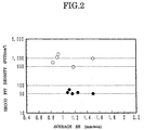
- Wafers were sliced from the obtained single crystal ingots by using a wire saw, and processed by chamfering, lapping, etching, and mirror polishing in the substantially same conditions to afford two kinds of mirror surface silicon single crystal wafers having a diameter of 6 inches, which were different in either they were doped or not doped with nitrogen.
- the silicon single crystal wafers obtained above were subjected to Secco etching, and the pit density was measured by microscopy to determine the density of crystal defects (grown-in defects).
- the results of the measurement are shown in Fig. 2.
- the black circles represent the results of the wafers doped with nitrogen, and the white circles represent the results of the wafers not doped with nitrogen.
- SOI substrates were produced according to the process steps shown in Fig. 1. Wafers doped with nitrogen were used for both of the bond wafer and the base wafer in the examples, and wafers not doped with nitrogen were used for both of the bond wafer and the base wafer in the comparative examples.
- Each bond wafer was subjected to a heat treatment at 1050°C in an atmosphere containing oxygen to form an oxide layer having a thickness of 0.2 ⁇ m on the surface of the bond wafer, and closely contacted with a base wafer, and they were firmly bonded by a heat treatment for bonding at 1100°C for 2 minutes. Then, the bond wafer was ground and polished, and subjected to vapor phase etching to produce an SOI substrate having an SOI layer of a thickness of about 0.2 ⁇ m.
- etch pits would be formed when the substrate is immersed in 50% aqueous solution of HF for 10 minutes, since HF reaches the buried oxide layer through the penetrating defects and etches the oxide layer. Since these etch pits formed on the oxide layer can be observed by an optical microscope through the thin SOI layer, the number of the pits in regions of about 10 cm 2 in total was determined by scanning the wafer surface along the direction of its diameter.
- the melt may or may not be applied with a magnetic field, and therefore the Czochralski method used for the present invention include the so-called MCZ method in which a magnetic field is applied.
- the present invention can of course afford the advantages at a higher oxygen concentration, e.g., 1.2 to 1.5 ⁇ 10 18 atoms/cm 3 or higher.
- the aforementioned embodiment was explained mainly for the case where two pieces of silicon wafers are bonded to produce an SOI substrate, but the present invention is of course effective for reducing crystal defects in the SOI layer also in a case where a silicon wafer produced by the CZ method and an insulator substrate made of quartz, silicon carbide, silicon nitride, alumina, sapphire, other ceramic materials or the like are bonded to form a bonded SOI substrate, and applicable to such a case.
Landscapes
- Crystals, And After-Treatments Of Crystals (AREA)
- Recrystallisation Techniques (AREA)
Applications Claiming Priority (2)
| Application Number | Priority Date | Filing Date | Title |
|---|---|---|---|
| JP16930998 | 1998-06-02 | ||
| JP16930998 | 1998-06-02 |
Publications (2)
| Publication Number | Publication Date |
|---|---|
| EP0969505A2 true EP0969505A2 (de) | 2000-01-05 |
| EP0969505A3 EP0969505A3 (de) | 2003-03-26 |
Family
ID=15884153
Family Applications (1)
| Application Number | Title | Priority Date | Filing Date |
|---|---|---|---|
| EP99110019A Ceased EP0969505A3 (de) | 1998-06-02 | 1999-05-21 | SOI Substrat |
Country Status (4)
| Country | Link |
|---|---|
| US (1) | US6224668B1 (de) |
| EP (1) | EP0969505A3 (de) |
| KR (1) | KR100592965B1 (de) |
| TW (1) | TW552323B (de) |
Cited By (10)
| Publication number | Priority date | Publication date | Assignee | Title |
|---|---|---|---|---|
| EP1170405A4 (de) * | 1999-11-12 | 2003-06-11 | Shinetsu Handotai Kk | Siliziumeinkristallwafer, verfahren zu dessen herstellung und soi wafer |
| WO2003061012A1 (en) * | 2002-01-09 | 2003-07-24 | Shin-Etsu Handotai Co.,Ltd. | Soi wafer manufacturing method and soi wafer |
| WO2004073057A1 (ja) * | 2003-02-14 | 2004-08-26 | Sumitomo Mitsubishi Silicon Corporation | シリコンウェーハの製造方法 |
| US7285471B2 (en) | 2005-01-31 | 2007-10-23 | S.O.I.Tec Silicon On Insulator Technologies | Process for transfer of a thin layer formed in a substrate with vacancy clusters |
| US7394129B2 (en) | 2004-04-29 | 2008-07-01 | Siltronic Ag | SOI wafer and method for producing it |
| EP1605510A4 (de) * | 2003-03-18 | 2009-09-16 | Shinetsu Handotai Kk | Soi-wafer und verfahren zu seiner herstellung |
| EP1667209A4 (de) * | 2003-09-08 | 2009-12-30 | Sumco Corp | Soi-wafer und verfahren zu seiner herstellung |
| DE102008060275A1 (de) * | 2008-12-03 | 2010-06-10 | Austriamicrosystems Ag | Verfahren zum Strukturieren eines gebondeten Wafers und Waferanordnung |
| EP2461359A4 (de) * | 2009-07-10 | 2014-07-23 | Shanghai Simgui Technology Co | Verfahren zur formung eines substrats mit versenkter isolationsschicht |
| DE102021113540A1 (de) | 2021-02-12 | 2022-08-18 | Taiwan Semiconductor Manufacturing Co., Ltd. | Gewölbte membranstruktur für mems-bauelement |
Families Citing this family (19)
| Publication number | Priority date | Publication date | Assignee | Title |
|---|---|---|---|---|
| US6224668B1 (en) * | 1998-06-02 | 2001-05-01 | Shin-Etsu Handotai Co., Ltd. | Method for producing SOI substrate and SOI substrate |
| JP2001144275A (ja) * | 1999-08-27 | 2001-05-25 | Shin Etsu Handotai Co Ltd | 貼り合わせsoiウエーハの製造方法および貼り合わせsoiウエーハ |
| WO2001028000A1 (en) * | 1999-10-14 | 2001-04-19 | Shin-Etsu Handotai Co., Ltd. | Method for manufacturing soi wafer, and soi wafer |
| DE10014650A1 (de) * | 2000-03-24 | 2001-10-04 | Wacker Siltronic Halbleitermat | Halbleiterscheibe aus Silicium und Verfahren zur Herstellung der Halbleiterscheibe |
| JP3754897B2 (ja) * | 2001-02-09 | 2006-03-15 | キヤノン株式会社 | 半導体装置用基板およびsoi基板の製造方法 |
| JP4071476B2 (ja) * | 2001-03-21 | 2008-04-02 | 株式会社東芝 | 半導体ウェーハ及び半導体ウェーハの製造方法 |
| US6565652B1 (en) | 2001-12-06 | 2003-05-20 | Seh America, Inc. | High resistivity silicon wafer and method of producing same using the magnetic field Czochralski method |
| US6743722B2 (en) | 2002-01-29 | 2004-06-01 | Strasbaugh | Method of spin etching wafers with an alkali solution |
| US6794227B2 (en) | 2002-06-28 | 2004-09-21 | Seh America, Inc. | Method of producing an SOI wafer |
| US6896727B2 (en) | 2002-06-28 | 2005-05-24 | Seh America, Inc. | Method of determining nitrogen concentration within a wafer |
| CN100472001C (zh) * | 2003-02-25 | 2009-03-25 | 株式会社上睦可 | 硅晶片、soi衬底、硅单晶生长方法,硅晶片制造方法及soi衬底制造方法 |
| US20040195622A1 (en) * | 2003-04-07 | 2004-10-07 | United Microelectronics Corp. | Semiconductor structure with silicon on insulator |
| US20070090491A1 (en) * | 2003-04-07 | 2007-04-26 | United Microelectronics Corp. | Semiconductor structure with silicon on insulator |
| US7358586B2 (en) * | 2004-09-28 | 2008-04-15 | International Business Machines Corporation | Silicon-on-insulator wafer having reentrant shape dielectric trenches |
| US7211474B2 (en) * | 2005-01-18 | 2007-05-01 | International Business Machines Corporation | SOI device with body contact self-aligned to gate |
| JP2010278338A (ja) | 2009-05-29 | 2010-12-09 | Shin-Etsu Chemical Co Ltd | 界面近傍における欠陥密度が低いsos基板 |
| JP2010278337A (ja) * | 2009-05-29 | 2010-12-09 | Shin-Etsu Chemical Co Ltd | 表面欠陥密度が少ないsos基板 |
| JP5643509B2 (ja) * | 2009-12-28 | 2014-12-17 | 信越化学工業株式会社 | 応力を低減したsos基板の製造方法 |
| CN114586132A (zh) * | 2019-10-24 | 2022-06-03 | 信越半导体株式会社 | 半导体基板的制造方法及半导体基板 |
Citations (1)
| Publication number | Priority date | Publication date | Assignee | Title |
|---|---|---|---|---|
| US5935320A (en) * | 1996-09-12 | 1999-08-10 | Wacker Siltronic Gesellschaft Fur Halbleitermaterialien Ag | Process for producing silicon semiconductor wafers with low defect density |
Family Cites Families (10)
| Publication number | Priority date | Publication date | Assignee | Title |
|---|---|---|---|---|
| EP0162830A1 (de) * | 1984-04-19 | 1985-11-27 | Monsanto Company | Halbleitersubstrate |
| JPS60251190A (ja) * | 1984-05-25 | 1985-12-11 | Shin Etsu Handotai Co Ltd | シリコン単結晶の製造方法 |
| JPH0633235B2 (ja) | 1989-04-05 | 1994-05-02 | 新日本製鐵株式会社 | 酸化膜耐圧特性の優れたシリコン単結晶及びその製造方法 |
| JPH06103714B2 (ja) | 1990-11-22 | 1994-12-14 | 信越半導体株式会社 | シリコン単結晶の電気特性検査方法 |
| FR2681472B1 (fr) | 1991-09-18 | 1993-10-29 | Commissariat Energie Atomique | Procede de fabrication de films minces de materiau semiconducteur. |
| JP2785585B2 (ja) * | 1992-04-21 | 1998-08-13 | 信越半導体株式会社 | シリコン単結晶の製造方法 |
| JP3192000B2 (ja) * | 1992-08-25 | 2001-07-23 | キヤノン株式会社 | 半導体基板及びその作製方法 |
| JP3262945B2 (ja) * | 1994-08-10 | 2002-03-04 | 三菱マテリアル株式会社 | Soi基板の製造方法及びこの方法により製造されたsoi基板 |
| JP3262190B2 (ja) * | 1994-09-05 | 2002-03-04 | 三菱マテリアル株式会社 | Soi基板の製造方法及びこの方法により製造されたsoi基板 |
| US6224668B1 (en) * | 1998-06-02 | 2001-05-01 | Shin-Etsu Handotai Co., Ltd. | Method for producing SOI substrate and SOI substrate |
-
1999
- 1999-05-18 US US09/313,858 patent/US6224668B1/en not_active Expired - Lifetime
- 1999-05-21 EP EP99110019A patent/EP0969505A3/de not_active Ceased
- 1999-05-24 TW TW088108462A patent/TW552323B/zh not_active IP Right Cessation
- 1999-06-01 KR KR1019990019955A patent/KR100592965B1/ko not_active Expired - Lifetime
Patent Citations (1)
| Publication number | Priority date | Publication date | Assignee | Title |
|---|---|---|---|---|
| US5935320A (en) * | 1996-09-12 | 1999-08-10 | Wacker Siltronic Gesellschaft Fur Halbleitermaterialien Ag | Process for producing silicon semiconductor wafers with low defect density |
Cited By (19)
| Publication number | Priority date | Publication date | Assignee | Title |
|---|---|---|---|---|
| US6843847B1 (en) | 1999-11-12 | 2005-01-18 | Shin-Etsu Handotai Co., Ltd. | Silicon single crystal wafer and production method thereof and soi wafer |
| EP1170405A4 (de) * | 1999-11-12 | 2003-06-11 | Shinetsu Handotai Kk | Siliziumeinkristallwafer, verfahren zu dessen herstellung und soi wafer |
| WO2003061012A1 (en) * | 2002-01-09 | 2003-07-24 | Shin-Etsu Handotai Co.,Ltd. | Soi wafer manufacturing method and soi wafer |
| US7563319B2 (en) | 2003-02-14 | 2009-07-21 | Sumitomo Mitsubishi Silicon Corporation | Manufacturing method of silicon wafer |
| CN100397595C (zh) * | 2003-02-14 | 2008-06-25 | 三菱住友硅晶株式会社 | 硅片的制造方法 |
| EP1513193A4 (de) * | 2003-02-14 | 2007-02-28 | Sumco Corp | Verfahren zur herstellung eines silizium-wafers |
| WO2004073057A1 (ja) * | 2003-02-14 | 2004-08-26 | Sumitomo Mitsubishi Silicon Corporation | シリコンウェーハの製造方法 |
| EP1605510A4 (de) * | 2003-03-18 | 2009-09-16 | Shinetsu Handotai Kk | Soi-wafer und verfahren zu seiner herstellung |
| EP1667209A4 (de) * | 2003-09-08 | 2009-12-30 | Sumco Corp | Soi-wafer und verfahren zu seiner herstellung |
| US7394129B2 (en) | 2004-04-29 | 2008-07-01 | Siltronic Ag | SOI wafer and method for producing it |
| US8323403B2 (en) | 2004-04-29 | 2012-12-04 | Siltronic Ag | SOI wafer and method for producing it |
| US7285471B2 (en) | 2005-01-31 | 2007-10-23 | S.O.I.Tec Silicon On Insulator Technologies | Process for transfer of a thin layer formed in a substrate with vacancy clusters |
| DE102008060275A1 (de) * | 2008-12-03 | 2010-06-10 | Austriamicrosystems Ag | Verfahren zum Strukturieren eines gebondeten Wafers und Waferanordnung |
| DE102008060275B4 (de) * | 2008-12-03 | 2012-10-31 | Austriamicrosystems Ag | Verfahren zum Strukturieren eines gebondeten Wafers |
| EP2461359A4 (de) * | 2009-07-10 | 2014-07-23 | Shanghai Simgui Technology Co | Verfahren zur formung eines substrats mit versenkter isolationsschicht |
| DE102021113540A1 (de) | 2021-02-12 | 2022-08-18 | Taiwan Semiconductor Manufacturing Co., Ltd. | Gewölbte membranstruktur für mems-bauelement |
| US12134557B2 (en) | 2021-02-12 | 2024-11-05 | Taiwan Semiconductor Manufacturing Co., Ltd. | Arched membrane structure for MEMS device |
| US12209013B2 (en) | 2021-02-12 | 2025-01-28 | Taiwan Semiconductor Manufacturing Co., Ltd. | Arched membrane structure for MEMS device |
| DE102021113540B4 (de) | 2021-02-12 | 2025-04-30 | Taiwan Semiconductor Manufacturing Co., Ltd. | Gewölbte membranstruktur für mems-bauelement und verfahren zu ihrer herstellung |
Also Published As
| Publication number | Publication date |
|---|---|
| EP0969505A3 (de) | 2003-03-26 |
| TW552323B (en) | 2003-09-11 |
| US6224668B1 (en) | 2001-05-01 |
| KR100592965B1 (ko) | 2006-06-23 |
| KR20000005790A (ko) | 2000-01-25 |
Similar Documents
| Publication | Publication Date | Title |
|---|---|---|
| US6224668B1 (en) | Method for producing SOI substrate and SOI substrate | |
| US6858094B2 (en) | Silicon wafer and silicon epitaxial wafer and production methods therefor | |
| EP0942078B1 (de) | Verfahren zur Herstellung eines einkristallinen Siliciumwafers und durch das Verfahren hergestellter einkristalliner Siliciumwafer | |
| US7147711B2 (en) | Method of producing silicon wafer and silicon wafer | |
| KR100797212B1 (ko) | 고 저항성 지지체 상에 유용층을 구비한 기판의 제조 방법 | |
| EP1137069A1 (de) | Herstellungsverfahren für geklebten soi-wafer, und geklebter soi-wafer | |
| EP0962557B1 (de) | Einkristallines Siliziumwafer und Verfahren zu seiner Herstellung | |
| US7186628B2 (en) | Method of manufacturing an SOI wafer where COP's are eliminated within the base wafer | |
| JP2000211995A (ja) | シリコン単結晶ウエ―ハおよびシリコン単結晶ウエ―ハの製造方法 | |
| US8252404B2 (en) | High resistivity silicon wafers | |
| JP3618254B2 (ja) | Soi基板の製造方法 | |
| KR101007678B1 (ko) | Soi웨이퍼 및 그 제조방법 | |
| JP3771737B2 (ja) | シリコン単結晶ウエーハの製造方法 | |
| EP1589580B1 (de) | Soi-wafer und herstellungsverfahren dafür | |
| EP1557883A1 (de) | Soi-wafer und verfahren zum herstellen eines soi-wafers | |
| EP1138809A1 (de) | Siliziumwafer und verfahren zu desen herstellung | |
| JP2004265903A (ja) | Soiウエーハ及びその製造方法 | |
| JP2005072108A (ja) | Soiウェーハの製造方法及びsoiウェーハ |
Legal Events
| Date | Code | Title | Description |
|---|---|---|---|
| PUAI | Public reference made under article 153(3) epc to a published international application that has entered the european phase |
Free format text: ORIGINAL CODE: 0009012 |
|
| AK | Designated contracting states |
Kind code of ref document: A2 Designated state(s): AT BE CH CY DE DK ES FI FR GB GR IE IT LI LU MC NL PT SE |
|
| AX | Request for extension of the european patent |
Free format text: AL;LT;LV;MK;RO;SI |
|
| PUAL | Search report despatched |
Free format text: ORIGINAL CODE: 0009013 |
|
| AK | Designated contracting states |
Kind code of ref document: A3 Designated state(s): AT BE CH CY DE DK ES FI FR GB GR IE IT LI LU MC NL PT SE |
|
| AX | Request for extension of the european patent |
Extension state: AL LT LV MK RO SI |
|
| 17P | Request for examination filed |
Effective date: 20030702 |
|
| 17Q | First examination report despatched |
Effective date: 20030821 |
|
| AKX | Designation fees paid |
Designated state(s): DE FR GB |
|
| 17Q | First examination report despatched |
Effective date: 20030821 |
|
| RAP1 | Party data changed (applicant data changed or rights of an application transferred) |
Owner name: SHIN-ETSU HANDOTAI CO., LTD. |
|
| STAA | Information on the status of an ep patent application or granted ep patent |
Free format text: STATUS: THE APPLICATION HAS BEEN REFUSED |
|
| 18R | Application refused |
Effective date: 20090115 |