EP0969582A2 - Elément élastique isolant pour caler un bobinage, en particulier un bobinage de stator de machine électrique - Google Patents
Elément élastique isolant pour caler un bobinage, en particulier un bobinage de stator de machine électrique Download PDFInfo
- Publication number
- EP0969582A2 EP0969582A2 EP99810556A EP99810556A EP0969582A2 EP 0969582 A2 EP0969582 A2 EP 0969582A2 EP 99810556 A EP99810556 A EP 99810556A EP 99810556 A EP99810556 A EP 99810556A EP 0969582 A2 EP0969582 A2 EP 0969582A2
- Authority
- EP
- European Patent Office
- Prior art keywords
- metal spring
- insulating element
- spring core
- element according
- core
- Prior art date
- Legal status (The legal status is an assumption and is not a legal conclusion. Google has not performed a legal analysis and makes no representation as to the accuracy of the status listed.)
- Granted
Links
Images



Classifications
-
- H—ELECTRICITY
- H02—GENERATION; CONVERSION OR DISTRIBUTION OF ELECTRIC POWER
- H02K—DYNAMO-ELECTRIC MACHINES
- H02K3/00—Details of windings
- H02K3/46—Fastening of windings on the stator or rotor structure
- H02K3/48—Fastening of windings on the stator or rotor structure in slots
- H02K3/487—Slot-closing devices
Definitions
- the present invention relates to the field of rotating art electrical machines. It relates to an elastic insulating element for wedging a winding, in particular the stator winding, of an electrical machine in the provided grooves of a sheet metal body.
- Such an insulating element is e.g. from US-A-3,949,255 or US-A-4,200,816.
- Elastic insulating material elements are found particularly in the stators of rotating ones electrical machines for elastic fastening (wedging) of the stator winding use in the grooves of the sheet metal body.
- the stator windings are usually insulated conductor bundles with a rectangular cross-section, those with a small Play in the grooves of the stator body. To ensure that the To ensure winding in the slot, the wedging must be stressed due to the weight of the winding and electromagnetic forces during operation and withstand short circuit in such a way that no loosening and vibration the winding becomes possible.
- Conventional slot lock wedges especially for smaller machine units consist of a prism-shaped or machined insulating material.
- Insulating material is usually used with glass fiber reinforced epoxy resin (see e.g. U.S.-A-4,200,818).
- a plastic-elastic intermediate layer (Fleece, felt) these wedges are axially in the grooves of the laminated core tooth heads and partly in an impregnation process with the winding and the sheet metal body glued.
- Another conventional wedge design is based on the mode of operation of double wedges. Two superimposed flat wedges are in the keyways inserted, the biasing force by axially driving the a flat wedge is built (see e.g. US-A-3,949,255).
- Plastic wave springs US-A-3,949,255.
- elastic wave springs are between a rigid wedge and the winding (or between two rigid wedges).
- the necessary pretensioning force is achieved by defined compression the corrugated spring reached.
- a shrinkage of the filling with filling processes is caused by the spring spring is compensated.
- Another solution to elastic Wedging represents the use of elastic wedges Wedges or recessed wedges in the middle (convex-concave wedges) become flexibility the wedges increases and the preload forces are reduced. Even with this solution can be compensated to a certain extent.
- the insulating element has a strip-shaped metal spring core has, which is surrounded on all sides by a covering made of an insulating material.
- the essence of the invention is no longer the elastic element Insulated body to use, but the embedded metal spring core.
- the insulating material is only functional for the electrical insulation of the metal spring core and possibly in addition to the shape of the corresponding one Component necessary. Its contribution to the mechanical behavior of the component must on the other hand, be at most marginal.
- the metal spring core which is preferred made of a non-magnetic, resilient metal, in particular a stainless steel, and a thickness of a few millimeters, preferably between 2 and 3 mm, exhibits practically no flow behavior even at higher temperatures.
- a first preferred embodiment of the insulating element according to the invention is characterized in that the metal spring core has means by which limit eddy currents induced in the metal spring core. Hereby is prevented by the high air gap induction in the machine strong Eddy currents with the corresponding thermal effects in the elements be stimulated.
- the means for limiting induced eddy currents comprise slot-shaped incisions which are made in the longitudinal direction of the Metal spring core arranged in each case distributed from the longitudinal edges of the metal spring core protrude into the interior of the metal spring core. By the Providing the cuts, the metal spring core is divided into individual sectors. This ensures that possible loops in which eddy currents can flow limited to electrically and thermally uncritical geometrical dimensions become.
- the slit is to be arranged so that the mechanical spring action of the metal spring core remains optimal. This can be achieved, for example that the incisions alternate from the opposite Protrude longitudinal edges of the metal spring core into the interior of the metal spring core, and that the incisions starting from the different longitudinal edges overlap inside the metal spring core.
- the covering of the insulating material element according to the invention preferably consists made of a fiber-reinforced plastic, in particular a high-temperature thermoset or high temperature thermoplastic. This ensures that Put the wrapping or embedding material under pressure is negligibly small.
- additional means for improving the mechanical connection between the metal spring core and the casing is provided.
- the metal spring core with a Adhesion promoter is pretreated.
- the embedding material ensures an even application of force.
- the insulating material element according to the invention can optionally be used both as a slot wedge as well as a corrugated spring, and alone as a slot wedge or as a corrugated spring or in a combination of a slot wedge and a corrugated spring be used.
- the element is designed as a slot wedge, it can preferably be on the A concave cross-sectional profile on the bottom or a convex cross-section on the top exhibit. As a result, the elastic mechanical properties can be positive to be influenced.
- the metal spring core is corrugated.
- the waves preferably close with the longitudinal direction of the wave spring an angle of less than 90 °, in particular about 45 °.
- the metal spring core formed from a strip with straight longitudinal edges, and are for limitation the eddy currents provided in the metal spring core incisions run the incisions are substantially perpendicular to the shafts, which means simultaneously optimal elastic and electrical properties of the corrugated spring can be achieved.
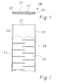
- FIG. 1 and 2 show in cross section and in a partially sectioned top view a first preferred embodiment of an insulating element according to the Invention in the form of a slot wedge 10.
- the slot wedge 10 is formed as a flat, elongated strip and laterally by two V-shaped ones Longitudinal sides 13, 14 delimited, so that there is an overall prismatic Cross-sectional profile (Fig. 1) results, as is customary and characteristic for slot wedges is.
- the slot lock wedge 10 comprises a metal spring core 11 in the form a sheet metal strip, which is surrounded on all sides by a covering 12 made of insulating material is that a direct contact of the core with the laminated sheet metal body of the Stators and thus stray metal flows with local hot spots and Danger of massive sheet metal closings prevented.
- the metal spring core 11 preferably has a simple rectangular cross-section and has a thickness of several Millimeters, especially in the range of 2 to 3 mm. It preferably exists made of a temperature-resistant non-magnetic metal with spring properties, for example a stainless steel.
- the envelope 12 has not only one insulating function, but at the same time serves to lock slot 10 by appropriate shaping in a simple manner the necessary prismatic To give cross-sectional profile.
- the metal spring core 11 is in the sheath 12 from a glass fiber reinforced Plastic embedded. All thermosets are also suitable as binders Thermoplastics, which can be sensibly selected depending on the intended temperature range are. It should be noted that the plastic is only functional in this application still for insulation of the metal spring core and possibly in addition to (e.g. prismatic) Shape of the slot wedge 10 is necessary. His contribution to mechanical behavior of the component, however, is at most marginal. However, it is ensure that the embedding material is placed under pressure should be negligibly small, which is why unreinforced plastics seem less suitable for this purpose. When choosing the fiber reinforced Plastic for the casing 12 and the pretreatment of the metal spring core 11 (e.g. through the use of an adhesion promoter) ensures good interface adhesion (Gluing) to ensure delamination caused by shear stresses to avoid.
- Gluing interface adhesion
- the Metal spring core 11 is not solid, but according to Fig. 2 by alternately arranged, from the longitudinal edges 13, 14 inside running and overlapping incisions 15 in individual sectors be divided, which are connected in a meandering shape. This ensures that possible loops in which eddy currents can flow on electrical and thermally uncritical geometric dimensions can be limited.
- the one with the incisions 15 connected slit is to be arranged so that the mechanical Spring action of the metal spring core 11 is optimally preserved.
- FIG. 4 Another embodiment of the slit with otherwise the same interior Structure is shown in Fig. 4.
- the incisions 15 of the starting from two longitudinal edges 13, 14 in pairs opposite and thus form one herringbone incised pattern.
- the intermediate sectors still holes 16 arranged distributed.
- holes 16 can of course also be of other types regular or irregularly shaped recesses are provided.
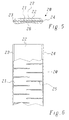
- a slot wedge shown in FIGS. 5 and 6 20 is the shape and slot for the metal spring core 21 (Incisions 25) of the metal spring core 11 from FIG. 2 taken over, however, that Cross-sectional profile of the sheath 22 according to FIG. 5 changed in such a way that the cover 22 is thicker overall, but on the underside 26 is concave or convex on the top 27.
- Convex-concave formation of the wedge is the total for a given thickness Flexibility increased and the preload reduced.
- the embodiments of the insulating element shown in FIGS. 7 to 9 according to the invention relate to the design as a corrugated spring 30 or 40, which together with appropriate slot lock wedges for elastic wedging the winding can be used.
- the wave spring 30 from FIGS. 7 and 8 comprises a corrugated metal spring core 31, which in turn of a sheath 32 made of fiber-reinforced insulating material (high-temperature epoxy) is surrounded.
- the corrugated metal spring core 31 is each with a glass thermoset prepreg assembled into a sandwich on the top and bottom and then cured in an appropriate waveform.
- the resulting one Corrugated spring 30 has the corrugation with corrugations which can be seen in the side view of FIG.
- the slit with the alternating and overlapping incisions 34 is also oriented at an oblique angle to the longitudinal axis, such that the incisions 34 are perpendicular to the direction of the shafts 33.
- the waves of the wave spring 40 are designed and oriented in the same way as the shafts 33 of the Corrugated spring 30 from Fig. 7, 8.
Landscapes
- Engineering & Computer Science (AREA)
- Power Engineering (AREA)
- Insulation, Fastening Of Motor, Generator Windings (AREA)
- Iron Core Of Rotating Electric Machines (AREA)
Applications Claiming Priority (2)
| Application Number | Priority Date | Filing Date | Title |
|---|---|---|---|
| DE19829578A DE19829578A1 (de) | 1998-07-02 | 1998-07-02 | Elastisches Isolierstoffelement für die Verkeilung einer Wicklung, insbesondere der Statorwicklung einer elektrischen Maschine |
| DE19829578 | 1998-07-02 |
Publications (3)
| Publication Number | Publication Date |
|---|---|
| EP0969582A2 true EP0969582A2 (fr) | 2000-01-05 |
| EP0969582A3 EP0969582A3 (fr) | 2001-03-07 |
| EP0969582B1 EP0969582B1 (fr) | 2007-01-24 |
Family
ID=7872756
Family Applications (1)
| Application Number | Title | Priority Date | Filing Date |
|---|---|---|---|
| EP99810556A Expired - Lifetime EP0969582B1 (fr) | 1998-07-02 | 1999-06-24 | Elément élastique isolant pour caler un bobinage, en particulier un bobinage de stator de machine électrique |
Country Status (5)
| Country | Link |
|---|---|
| US (1) | US6274961B1 (fr) |
| EP (1) | EP0969582B1 (fr) |
| CN (1) | CN100380782C (fr) |
| AT (1) | ATE352897T1 (fr) |
| DE (2) | DE19829578A1 (fr) |
Families Citing this family (4)
| Publication number | Priority date | Publication date | Assignee | Title |
|---|---|---|---|---|
| ITUD20010208A1 (it) * | 2001-12-14 | 2003-06-16 | Gisulfo Baccini | Motore lineare e procedimento di fabbricazione di tale motore lineare |
| ITUD20010209A1 (it) * | 2001-12-14 | 2003-06-16 | Gisulfo Baccini | Motore lineare e procedimento di fabbricazione di tale motore lineare |
| CN102133924B (zh) * | 2011-01-28 | 2013-01-16 | 扬州恒旺五金机械有限公司 | 用于船舶液压系统保压蓄能装置的波形弹簧机构 |
| CN102364825A (zh) * | 2011-11-23 | 2012-02-29 | 哈尔滨电机厂有限责任公司 | 大型空冷发电机定子线棒高导热槽内固定结构 |
Family Cites Families (21)
| Publication number | Priority date | Publication date | Assignee | Title |
|---|---|---|---|---|
| DE245805C (fr) * | ||||
| US871758A (en) * | 1906-10-18 | 1907-11-19 | Crocker Wheeler Co | Bridging-blocks for dynamo-electric machines. |
| US2015554A (en) * | 1933-12-08 | 1935-09-24 | Gen Electric | Magnetic wedge |
| US3437858A (en) * | 1966-11-17 | 1969-04-08 | Glastic Corp | Slot wedge for electric motors or generators |
| DE1953386A1 (de) * | 1969-10-23 | 1971-05-06 | Bbc Brown Boveri & Cie | Glasfaserverstaerktes Kunstharzprofil,insbesondere Nutverschlusskeil fuer elektrische Maschinen |
| DE2123520A1 (de) * | 1971-05-08 | 1972-11-16 | Licentia Patent-Verwaltungs-Gmbh, 6000 Frankfurt | Nutkeilanordnung |
| GB1430756A (en) | 1972-07-11 | 1976-04-07 | Reyrolle Parsons Ltd | Dynamo-electric machines |
| CH564872A5 (fr) * | 1973-11-05 | 1975-07-31 | Bbc Brown Boveri & Cie | |
| US4200816A (en) | 1978-05-11 | 1980-04-29 | Eaton Corporation | Wheel speed sensor including electro-magnetic pickup |
| US4200818A (en) * | 1978-08-01 | 1980-04-29 | Westinghouse Electric Corp. | Resin impregnated aromatic polyamide covered glass based slot wedge for large dynamoelectric machines |
| JPS55109148A (en) * | 1979-02-13 | 1980-08-22 | Nippon Rika Kogyosho:Kk | Method for manufacture of wedge for rotating electric machine |
| JPS55117448A (en) * | 1979-03-22 | 1980-09-09 | Mitsubishi Electric Corp | Method for assembling structure in slot of rotating-electric machine |
| DE3016990A1 (de) * | 1980-05-02 | 1981-11-12 | Kraftwerk Union AG, 4330 Mülheim | Vorrichtung zum fixieren von wicklungsstaeben in nuten elektrischer maschinen, insbesondere turbogeneratoren |
| CH662911A5 (de) * | 1982-06-23 | 1987-10-30 | Micafil Ag | Verfahren zur fixierung von wicklungen durch vorgespannte nutenverschlussteile und einrichtung zur durchfuehrung des verfahrens. |
| JPS5970158A (ja) * | 1982-10-13 | 1984-04-20 | Hitachi Ltd | 固定子線輪支持装置 |
| JPS59136039A (ja) * | 1983-01-26 | 1984-08-04 | Toshiba Corp | 回転電機 |
| US4572980A (en) * | 1984-03-08 | 1986-02-25 | General Electric Company | Stator core for large electric generator with dual dovetail slots for engaging wedges |
| US4607183A (en) * | 1984-11-14 | 1986-08-19 | General Electric Company | Dynamoelectric machine slot wedges with abrasion resistant layer |
| DE4327775A1 (de) * | 1993-08-18 | 1995-02-23 | Abb Management Ag | Nutverschlußanordnung |
| DE4337628A1 (de) * | 1993-11-04 | 1995-05-11 | Abb Management Ag | Rotor eines Turbogenerators mit direkter Gaskühlung der Erregerwicklung |
| DE19543122A1 (de) * | 1995-11-18 | 1997-05-22 | Asea Brown Boveri | Leiterstab |
-
1998
- 1998-07-02 DE DE19829578A patent/DE19829578A1/de not_active Withdrawn
-
1999
- 1999-06-24 DE DE59914161T patent/DE59914161D1/de not_active Expired - Lifetime
- 1999-06-24 EP EP99810556A patent/EP0969582B1/fr not_active Expired - Lifetime
- 1999-06-24 AT AT99810556T patent/ATE352897T1/de active
- 1999-06-30 US US09/343,394 patent/US6274961B1/en not_active Expired - Fee Related
- 1999-07-02 CN CNB991101154A patent/CN100380782C/zh not_active Expired - Fee Related
Also Published As
| Publication number | Publication date |
|---|---|
| DE19829578A1 (de) | 2000-01-05 |
| CN100380782C (zh) | 2008-04-09 |
| US6274961B1 (en) | 2001-08-14 |
| ATE352897T1 (de) | 2007-02-15 |
| EP0969582A3 (fr) | 2001-03-07 |
| CN1241060A (zh) | 2000-01-12 |
| EP0969582B1 (fr) | 2007-01-24 |
| DE59914161D1 (de) | 2007-03-15 |
Similar Documents
| Publication | Publication Date | Title |
|---|---|---|
| EP1947755B1 (fr) | Stator d'une machine électrique | |
| DE69402617T2 (de) | Schutzvorrichtung für das Ankerende eines gewickelten Rotors | |
| DE102007063307A1 (de) | Montageverfahren zum Einpassen eines Permanentmagneten in ein Halteelement | |
| DE102010016241A1 (de) | Stator für eine rotierende elektrische Maschine und Verfahren zur Herstellung des Stators | |
| DE3901230C1 (fr) | ||
| WO2017016735A1 (fr) | Stator amélioré pour une machine électrique | |
| WO2016066389A2 (fr) | Rotor d'une machine électrique, machine électrique et procédé de fabrication du rotor d'une machine électrique | |
| DE2358367C2 (de) | Federelastische Verspannung zwischen Wicklung und Nutenkeil einer rotierenden elektrischen Maschine | |
| DE112006001929T5 (de) | Rotornabe und -baugruppe für eine Permanentmagnet-Elektromaschine | |
| DE102013110356B4 (de) | Ultraschallaktor | |
| DE3538506C2 (de) | Elektromotor mit sphärischem Magnetspalt | |
| DE102019129243A1 (de) | Rotor für eine elektrische Maschine, zugehöriges Herstellungsverfahren und elektrische Maschine zum Antreiben eines Fahrzeugs | |
| WO1999060883A2 (fr) | Cylindre rotatif pour un appareil epilatoire | |
| EP0969582B1 (fr) | Elément élastique isolant pour caler un bobinage, en particulier un bobinage de stator de machine électrique | |
| DE69827311T2 (de) | Rotorwelle für einen Elektromotor und Herstellungsverfahren für eine Rotorwelle | |
| WO2016075248A1 (fr) | Cale de fixation | |
| DE3308006C2 (de) | Rotierende Elektromaschine mit Luftspaltwicklung | |
| WO2011091791A2 (fr) | Élément de fixation pour fixer un aimant sur un composant d'une machine électrique, module et composant doté d'un élément de fixation de ce type | |
| DE69819101T2 (de) | Verbesserungen an Vibrationswellenmotoren | |
| DE102022203163A1 (de) | Blechpaket für eine E-Maschine | |
| DE2150163C3 (de) | Anordnung zur Versteifung von Wickelköpfen in elektrischen Maschinen | |
| WO2019076543A1 (fr) | Stator et machine électrique pourvue d'un stator | |
| EP0238933A2 (fr) | Support de tête de bobinage pour machines électriques | |
| EP1656725B1 (fr) | Moteur a reluctance | |
| EP3591807B1 (fr) | Rotor pour un moteur à reluctance synchrone |
Legal Events
| Date | Code | Title | Description |
|---|---|---|---|
| PUAI | Public reference made under article 153(3) epc to a published international application that has entered the european phase |
Free format text: ORIGINAL CODE: 0009012 |
|
| AK | Designated contracting states |
Kind code of ref document: A2 Designated state(s): AT DE FR GB IT |
|
| AX | Request for extension of the european patent |
Free format text: AL;LT;LV;MK;RO;SI |
|
| PUAL | Search report despatched |
Free format text: ORIGINAL CODE: 0009013 |
|
| AK | Designated contracting states |
Kind code of ref document: A3 Designated state(s): AT BE CH CY DE DK ES FI FR GB GR IE IT LI LU MC NL PT SE |
|
| AX | Request for extension of the european patent |
Free format text: AL;LT;LV;MK;RO;SI |
|
| 17P | Request for examination filed |
Effective date: 20010730 |
|
| AKX | Designation fees paid |
Free format text: AT DE FR GB IT |
|
| RAP1 | Party data changed (applicant data changed or rights of an application transferred) |
Owner name: ALSTOM |
|
| RAP1 | Party data changed (applicant data changed or rights of an application transferred) |
Owner name: ALSTOM (SWITZERLAND) LTD |
|
| RAP1 | Party data changed (applicant data changed or rights of an application transferred) |
Owner name: ALSTOM TECHNOLOGY LTD |
|
| 17Q | First examination report despatched |
Effective date: 20050610 |
|
| GRAP | Despatch of communication of intention to grant a patent |
Free format text: ORIGINAL CODE: EPIDOSNIGR1 |
|
| GRAS | Grant fee paid |
Free format text: ORIGINAL CODE: EPIDOSNIGR3 |
|
| GRAA | (expected) grant |
Free format text: ORIGINAL CODE: 0009210 |
|
| AK | Designated contracting states |
Kind code of ref document: B1 Designated state(s): AT DE FR GB IT |
|
| REG | Reference to a national code |
Ref country code: GB Ref legal event code: FG4D Free format text: NOT ENGLISH |
|
| REF | Corresponds to: |
Ref document number: 59914161 Country of ref document: DE Date of ref document: 20070315 Kind code of ref document: P |
|
| GBT | Gb: translation of ep patent filed (gb section 77(6)(a)/1977) |
Effective date: 20070222 |
|
| ET | Fr: translation filed | ||
| PLBE | No opposition filed within time limit |
Free format text: ORIGINAL CODE: 0009261 |
|
| STAA | Information on the status of an ep patent application or granted ep patent |
Free format text: STATUS: NO OPPOSITION FILED WITHIN TIME LIMIT |
|
| 26N | No opposition filed |
Effective date: 20071025 |
|
| PGFP | Annual fee paid to national office [announced via postgrant information from national office to epo] |
Ref country code: FR Payment date: 20110603 Year of fee payment: 13 |
|
| PGFP | Annual fee paid to national office [announced via postgrant information from national office to epo] |
Ref country code: AT Payment date: 20110523 Year of fee payment: 13 Ref country code: GB Payment date: 20110523 Year of fee payment: 13 |
|
| PGFP | Annual fee paid to national office [announced via postgrant information from national office to epo] |
Ref country code: IT Payment date: 20110616 Year of fee payment: 13 |
|
| PGFP | Annual fee paid to national office [announced via postgrant information from national office to epo] |
Ref country code: DE Payment date: 20110630 Year of fee payment: 13 |
|
| REG | Reference to a national code |
Ref country code: AT Ref legal event code: MM01 Ref document number: 352897 Country of ref document: AT Kind code of ref document: T Effective date: 20120624 |
|
| GBPC | Gb: european patent ceased through non-payment of renewal fee |
Effective date: 20120624 |
|
| PG25 | Lapsed in a contracting state [announced via postgrant information from national office to epo] |
Ref country code: IT Free format text: LAPSE BECAUSE OF NON-PAYMENT OF DUE FEES Effective date: 20120624 |
|
| REG | Reference to a national code |
Ref country code: FR Ref legal event code: ST Effective date: 20130228 |
|
| PG25 | Lapsed in a contracting state [announced via postgrant information from national office to epo] |
Ref country code: DE Free format text: LAPSE BECAUSE OF NON-PAYMENT OF DUE FEES Effective date: 20130101 Ref country code: FR Free format text: LAPSE BECAUSE OF NON-PAYMENT OF DUE FEES Effective date: 20120702 Ref country code: GB Free format text: LAPSE BECAUSE OF NON-PAYMENT OF DUE FEES Effective date: 20120624 |
|
| REG | Reference to a national code |
Ref country code: DE Ref legal event code: R119 Ref document number: 59914161 Country of ref document: DE Effective date: 20130101 |
|
| PG25 | Lapsed in a contracting state [announced via postgrant information from national office to epo] |
Ref country code: AT Free format text: LAPSE BECAUSE OF NON-PAYMENT OF DUE FEES Effective date: 20120624 |