EP0969603B1 - Procédé et dispositif de réception de signaux à spectre étalé - Google Patents
Procédé et dispositif de réception de signaux à spectre étalé Download PDFInfo
- Publication number
- EP0969603B1 EP0969603B1 EP19990111609 EP99111609A EP0969603B1 EP 0969603 B1 EP0969603 B1 EP 0969603B1 EP 19990111609 EP19990111609 EP 19990111609 EP 99111609 A EP99111609 A EP 99111609A EP 0969603 B1 EP0969603 B1 EP 0969603B1
- Authority
- EP
- European Patent Office
- Prior art keywords
- receiving
- spread spectrum
- spectrum signal
- synch
- chip
- Prior art date
- Legal status (The legal status is an assumption and is not a legal conclusion. Google has not performed a legal analysis and makes no representation as to the accuracy of the status listed.)
- Expired - Lifetime
Links
- 238000001228 spectrum Methods 0.000 title claims description 25
- 238000000034 method Methods 0.000 title claims description 16
- 238000012935 Averaging Methods 0.000 claims description 14
- 230000001427 coherent effect Effects 0.000 description 4
- 230000000694 effects Effects 0.000 description 3
- 230000001360 synchronised effect Effects 0.000 description 3
- 230000036962 time dependent Effects 0.000 description 3
- 238000013459 approach Methods 0.000 description 2
- 238000007796 conventional method Methods 0.000 description 2
- 238000010586 diagram Methods 0.000 description 2
- 238000005562 fading Methods 0.000 description 2
- 238000007792 addition Methods 0.000 description 1
- 239000000969 carrier Substances 0.000 description 1
- 230000003111 delayed effect Effects 0.000 description 1
- 238000001514 detection method Methods 0.000 description 1
- 230000010363 phase shift Effects 0.000 description 1
Images


Classifications
-
- H—ELECTRICITY
- H04—ELECTRIC COMMUNICATION TECHNIQUE
- H04B—TRANSMISSION
- H04B1/00—Details of transmission systems, not covered by a single one of groups H04B3/00 - H04B13/00; Details of transmission systems not characterised by the medium used for transmission
- H04B1/69—Spread spectrum techniques
- H04B1/707—Spread spectrum techniques using direct sequence modulation
Definitions
- the present invention relates to a method and apparatus for receiving spread spectrum (SS) signal which is to be synchronized with Pseudo-Noise (PN) sequence for de-spreading.
- SS spread spectrum
- PN Pseudo-Noise
- the synch chip timing between the spread spectrum (SS) signal and the Pseudo-Noise (PN) sequence which is used for de-spreading is detected by independent antennas to combine the mutipath signalsfrom each anntennas, as disclosed, for example, in JP 9-64845 A (1997).
- independent receiving units 111 to 11K with antennas 101 to 10K are connected in parallel with antenna diversity combining unit 121.
- receiving units 111 to 11K are identical.
- the signal received by antenna 101 and spread spectrum (SS) sequence from PN sequence generator 6 are inputted into sliding correlation calculation means 7.
- the calculation of the sliding correlation is a multiplication and summation concerning with the SS signal and PN sequence over a prescribed period which is given by one to several symbol periods in general.
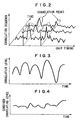
- the correlation sequence level outputted from sliding correlation calculation means 7 has peaks at the synch chip timings of a plurality of mutipath signals received by antenna 101, as shown in Figure 2.
- correlation averaging means 8 which averages the correlation values in each of the chip timings over a prescribed period. Then, correlation averaging means 8 outputs delay profile 91.
- Peak detector means 9 outputs N synch chip timings of the mutipath signals, by detecting N peaks in delay profile 91. For example, peak detector means 9 detects N peaks in the order of their levels which are distant by one or more chips with each other.
- PN sequence outputted from PN sequence generator 6 is inputted into delay circuits 21 to 2N, and then, inputted into multipliers 31 to 3N to be multiplied by SS signal from antenna 101.
- de-spread SS signals are inputted into coherent detector means 41 to 4N which compensates for the pkase shift of de-spread SS signal on the propagation path and are combined by path combining means 5.
- correlation sequence which is outputted from sliding correlation calculation means 7 has peaks at the synch chip timings of the muli-path waves received by antenna 101.
- the peak levels at the synch chip timings vary due to the fading caused by the movement of the connected mobile station, as shown in Figure 3.
- correlation averaging means 8 can output delay profile 91 which is clearly discriminated from the noise level.
- Each receiving unit comprises a threshold or peak detecting device the outputs of which are then connected to a common timing reconciliation device to obtain a common time location of the signal peaks.
- an object of the present invention is to provide a spread spectrum (SS) signal receiver, wherein the synch chip timings of mutipath signals can be detected rapidly, even when a doppler frequency is low due to a slow movement of a mobile station.
- SS spread spectrum
- SS signals are received by a plurality of antennas. Then, a delay profile as a correlation between an SS signal and a prescribed PN sequence for each antenna is calculated. Then, the delay profiles calculated for every antenna are combined. Then, the synch chip timings are detected from the combined delay profile. Then, the detected synch timings are utilized commonly by each receiving unit. Then, each multipath signal is de-spread on the synch chip timing. Then, the de-spread multipath signals are combined in each receiving unit to obtain path diversity effect. Finally, the combined signals in in each receiver units are combined to obtain antenna diversity effect.
- SS signals are received by a plurality of antennas. Then, a delay profile as a correlation between an SS signal and a prescribed PN sequence for each antenna is calculated. Then, the delay profiles calculated for every antenna are combined. Then, the synch chip timings are detected from the combined delay profile. Then, the detected synch timings are utilized commonly by each receiving unit. Then, each multipath signal is de-
- each SS signal received by each antenna is used to calculate each delay profile in parallel, from which a synch chip timing is detected.
- the detected timing is fed commonly to each antenna.
- a stable delay profile can be obtained in a shorter period of time, in comparison with the conventional technique wherein the correlation is averaged before combining the delay profiles.
- the synch chip timing is detected after combining the delay profiles from a set of independent antennas.
- the tracking capability can be improved, even when the synch chip timing varies rapidly, due to the fast movement of mobile station.
- the number of peak detector means is reduced, because the peak is detected after combining the delay profiles.
- the receiver of the present invention as shown in Figure 1 is provided with delay profile combining means 122 for combining the delay profiles from a plurality of parallel receiving units 111 to 11K.
- delay profile combining means 122 On the basis of the output from delay profile combining means 122, synch chip timings of mutipath signals are detected by peak detector means 123. Further, the detected timing is outputted commonly to receiving units 111 to 11K.
- receiving units 111 to 11K are identical.
- Receiving unit 111 comprises antenna 101, path combination receiving means 1, PN sequence generator 6, sliding correlation calculation means 7, and correlation averaging means 8.
- Path combination receiving means 1 further comprises, a plurality of delay circuits 21 to 2N, multipliers 31 to 3N, detector means 41 to 4N, and path combining means 5.
- PN sequence generator 6 outputs a prescribed PN sequence with an arbitrary chip timing.
- Sliding correlation calculation means 7 calculates correlation sequences between SS signal from antenna 101 and PN sequence from PN sequence generator 6 under a plurality of chip timings.
- the correlation calculated by sliding correlation calculation means 7 is a summation, over a prescribed period, of multiplications of SS signal and PN sequence.
- Correlation averaging means 8 averages over a prescribed period the correlation under a chip timing outputted from sliding correlation calculation means 7, whereby correlation averaging means 8 outputs delay profile 91 whose peak and noise are smoothed.
- Delay profile combining means 122 combines delay profiles 91 to 9K obtained by receiving units 111 to 11K, respectively, to output a combined delay profile.
- Peak detector means 123 detects N peaks from the combined delay profile outputted from delay profile combining means 122 to supply receiving units 111 to 11K with synch chip timings which correspond to the N peaks.
- Delay circuits 21 to 2N delay the PN sequences from PN sequence generator 6 on the basis of the synch chip timings from peak detector means 123.
- the PN sequences delayed by delay circuits 21 to 2N are synchronized with the SS signal.
- Multipliers 31 to 3N multiplies, for de-spreading, the SS signal from antenna 101 by the synchronized PN sequence through delay circuits 21 to 2N.
- Coherent detector means 41 to 4N compensate for the phase shift of the de-spread signal from multipliers 31 to 3N and feed path combining means 5 with the output from coherent detector 41.
- Path combining means 5 combines the signals after coherent detection for each path which is an output of path combination receiving means 1 for receiving unit 111.
- the output of path combination receiving means 1 are fed to antenna diversity combining means 121.
- Antenna diversity combining means 121 combines the outputs of each path combination receiving means for receiving units 111 to 11K.
- delay profile combining means 122 is explained here.
- the correlation peaks at the synch chip timings in delay profiles are assumed to vary independently with each other, because the condition wherein the antenna is spaced sufficiently far apart from each other in comparison with the carrier wavelength is needed to obtain the antenna diversity effect.
- the synch chip timings are assumed in general to be almost identical for every SS signal received by independent antennas, because the distance between the separated independent antennas is small enough for the carriers in the duration of a chip to arrive simultaneously.
- the fluctuation of the correlation peak level can be suppressed by combining delay profiles 91 to 9K from receiving units 111 to 11k, using delay profile combining means 122.
- the combined delay profile outputted from delay profile combining means 122 has an averaged and smoothed level fluctuation, as shown in Figure 4.
- the synch chip timing can be detected rapidly, and a capability of following a mobile station can be improved, even when the synch chip timing varies rapidly, due to the fast movement of mobile station.
- the fastest method amongst various methods for combining delay profiles in delay profile combining means 122 is to add the delay profiles at the same chip timing. According to the fastest method, the peaks in the combined profile becomes great enough to extract accurately the synch chip timings, because the noise level which is included only in a certain delay profile is averaged and reduced in the combined profile.
- Each of the delay profiles may be given a weight before combining.
- the correlation levels at a synch chip timing in the past preferably, the past which is as latest as the present time may be summed up. Then, on the basis of the summation, the weight for each profile is decided.
- the summation at the past times approaches the summation at the present times, when the past times approaches the present times.
- the weight is made great for the profile which gives a greater summation, because such a profile is vitally significant to detect the synch chip timing.
- the weight may be also decided on the basis of the noise level included in the received SS signal.
- the noise level may be an average correlation at the chip timing except the present synch chip timing.
- the noise level may also be a noise level of a de-spread signal.
- the weight is made great for the profile which gives a smaller noise, because such a profile is vitally significant to detect the synch chip timing.
- the weight may be decided on the basis of the ratio of a noise level of received SS signal to a correlation level in the past.
- the weight is made great for the profile which gives a smaller ratio.
- the synch chip timing is decided on the basis of both the correlation level and noise level.
Landscapes
- Engineering & Computer Science (AREA)
- Computer Networks & Wireless Communication (AREA)
- Signal Processing (AREA)
- Radio Transmission System (AREA)
- Synchronisation In Digital Transmission Systems (AREA)
- Mobile Radio Communication Systems (AREA)
Claims (9)
- Procédé de réception de signal à spectre étalé dans lequel chacune d'une pluralité de synchronisations d'élément de synchronisation est délivrée à une pluralité d'unités de réception (111, 112, ..., 11K), des parcours à chacune desdites unités de réception sont combinés indépendamment et les parcours combinés sont combinés pour obtenir une sortie désétalée, ledit procédé comprenant les étapes consistant à :recevoir ledit signal à spectre étalé en utilisant une pluralité d'antennes (101, 102, ..., 10K), une pour chacune desdites unités de réception ;calculer des corrélations entre ledit signal à spectre étalé et une séquence de pseudo-bruit (PN) dans chacune desdites unités de réception ;générer un profil de retard sur la base desdites corrélations dans chacune desdites unités de réception ;additionner les profils de retard obtenus à partir de chacune desdites unités de réception ; etdétecter lesdites synchronisations d'élément de synchronisation sur la base des profils de retard additionnés.
- Procédé de réception de signal à spectre étalé selon la revendication 1, ledit procédé comprenant en outre les étapes consistant à :faire la moyenne desdites corrélations dans chacune desdites unités de réception (111, 112, ..., 11K) ; etextraire un ou plusieurs pics comme lesdites synchronisations d'élément de synchronisation à partir desdits profils de retard combinés.
- Procédé de réception de signal à spectre étalé selon la revendication 1 ou 2, dans lequel lesdits profils de retard sont additionnés pour chaque synchronisation d'élément.
- Procédé de réception de signal à spectre étalé selon la revendication 1 ou 2, dans lequel un poids est donné à chacune desdites corrélations et chacun desdits profils de retard est additionné à chaque synchronisation d'élément.
- Procédé de réception de signal à spectre étalé selon la revendication 4, dans lequel ledit poids est déterminé sur la base de corrélations précédentes.
- Procédé de réception de signal à spectre étalé selon la revendication 4, dans lequel ledit poids est déterminé sur la base d'un bruit du signal à spectre étalé.
- Procédé de réception de signal à spectre étalé selon la revendication 4, dans lequel ledit poids est déterminé sur la base d'un rapport de corrélations précédentes et d'un bruit du signal à spectre étalé.
- Dispositif de réception de signal à spectre étalé, lequel comprend :une pluralité d'unités de réception (111, 112, ..., 11K), chacune comprenant :une antenne (101, 102, ..., 10K) pour recevoir un signal à spectre étalé ;un moyen de calcul de corrélations à glissement (7) pour calculer des corrélations entre ledit signal à spectre étalé et une séquence de pseudo-bruit à une pluralité de synchronisations d'élément ; etun moyen récepteur de combinaison de parcours (1) pour combiner des parcours dudit signal à spectre étalé en utilisant lesdites synchronisations d'élément de synchronisation ;chaque unité de réception est adaptée en outre pour multiplier chaque corrélation par un poids et pour produire un profil de retard sur la base desdites corrélations pondérées ;un moyen de combinaison de profils de retard (122) pour additionner à chaque synchronisation d'élément les profils de retard obtenus à partir de chacune de ladite pluralité de unités de réception ;un moyen de détection de pics (123) pour détecter, dans la sortie dudit moyen de combinaison de profils de retard, un ou plusieurs pics comme lesdites synchronisations d'élément de synchronisation ;un moyen de combinaison de diversité d'antenne (121) pour combiner les sorties dudit moyen récepteur de combinaison de parcours.
- Dispositif de réception de signal à spectre étalé selon la revendication 8, dans lequel chaque unité de réception comprend en outre :un moyen pour effectuer la moyenne de corrélations (8) pour faire la moyenne de la sortie dudit moyen de calcul de corrélation à glissement.
Applications Claiming Priority (2)
| Application Number | Priority Date | Filing Date | Title |
|---|---|---|---|
| JP18225798A JP2982795B1 (ja) | 1998-06-29 | 1998-06-29 | スペクトラム拡散信号受信方法および受信機 |
| JP18225798 | 1998-06-29 |
Publications (3)
| Publication Number | Publication Date |
|---|---|
| EP0969603A2 EP0969603A2 (fr) | 2000-01-05 |
| EP0969603A3 EP0969603A3 (fr) | 2003-08-20 |
| EP0969603B1 true EP0969603B1 (fr) | 2006-03-01 |
Family
ID=16115100
Family Applications (1)
| Application Number | Title | Priority Date | Filing Date |
|---|---|---|---|
| EP19990111609 Expired - Lifetime EP0969603B1 (fr) | 1998-06-29 | 1999-06-15 | Procédé et dispositif de réception de signaux à spectre étalé |
Country Status (5)
| Country | Link |
|---|---|
| US (1) | US6282229B1 (fr) |
| EP (1) | EP0969603B1 (fr) |
| JP (1) | JP2982795B1 (fr) |
| CA (1) | CA2276430C (fr) |
| DE (1) | DE69930029T2 (fr) |
Families Citing this family (15)
| Publication number | Priority date | Publication date | Assignee | Title |
|---|---|---|---|---|
| JP3369513B2 (ja) * | 1999-07-02 | 2003-01-20 | 松下電器産業株式会社 | 通信端末装置及び無線受信方法 |
| JP3367475B2 (ja) * | 1999-07-06 | 2003-01-14 | 日本電気株式会社 | 無線通信機および無線通信機の消費電力制御方法 |
| JP3943305B2 (ja) * | 2000-01-19 | 2007-07-11 | 三菱電機株式会社 | スペクトル拡散受信装置、およびスペクトル拡散受信方法 |
| US6836507B1 (en) * | 2000-08-14 | 2004-12-28 | General Dynamics Decision Systems, Inc. | Symbol synchronizer for software defined communications system signal combiner |
| JP3544644B2 (ja) * | 2000-09-29 | 2004-07-21 | 松下電器産業株式会社 | 無線受信装置及び無線受信装置におけるブランチ間遅延差検出方法 |
| JP3421314B2 (ja) * | 2000-10-04 | 2003-06-30 | 松下電器産業株式会社 | パス選択装置及びパス選択方法 |
| JP3856126B2 (ja) | 2002-05-21 | 2006-12-13 | 日本電気株式会社 | パスタイミング検出方法、パスタイミング検出装置及び適応アレーアンテナシステム |
| US8396151B2 (en) * | 2006-10-19 | 2013-03-12 | Qualcomm Incorporated | Timing tracking in a multiple receive antenna system |
| US7782926B2 (en) * | 2008-03-18 | 2010-08-24 | On-Ramp Wireless, Inc. | Random phase multiple access communication interface system and method |
| US20090239550A1 (en) * | 2008-03-18 | 2009-09-24 | Myers Theodore J | Random phase multiple access system with location tracking |
| US7733945B2 (en) * | 2008-03-18 | 2010-06-08 | On-Ramp Wireless, Inc. | Spread spectrum with doppler optimization |
| US7773664B2 (en) * | 2008-03-18 | 2010-08-10 | On-Ramp Wireless, Inc. | Random phase multiple access system with meshing |
| KR101050132B1 (ko) | 2009-03-26 | 2011-07-22 | 성균관대학교산학협력단 | 대역 확산 부호 획득 장치 및 그 방법 |
| US8737944B2 (en) * | 2010-05-21 | 2014-05-27 | Kathrein-Werke Kg | Uplink calibration system without the need for a pilot signal |
| JP5599677B2 (ja) * | 2010-08-18 | 2014-10-01 | ラピスセミコンダクタ株式会社 | ダイバシティ受信装置及びダイバシティ受信方法 |
Family Cites Families (10)
| Publication number | Priority date | Publication date | Assignee | Title |
|---|---|---|---|---|
| US5237587A (en) * | 1992-11-20 | 1993-08-17 | Magnavox Electronic Systems Company | Pseudo-noise modem and related digital correlation method |
| KR0164250B1 (ko) * | 1993-08-06 | 1999-02-01 | 고지 오보시 | 스펙트럼 확산 통신용 수신기 및 중계기 |
| JPH0774687A (ja) | 1993-09-03 | 1995-03-17 | Kokusai Denshin Denwa Co Ltd <Kdd> | ダイバーシチ方式 |
| US5790588A (en) * | 1995-06-07 | 1998-08-04 | Ntt Mobile Communications Network, Inc. | Spread spectrum transmitter and receiver employing composite spreading codes |
| JPH0964845A (ja) | 1995-08-25 | 1997-03-07 | Matsushita Electric Ind Co Ltd | 高速伝送用スペクトラム拡散通信装置 |
| JP2723094B2 (ja) * | 1995-11-07 | 1998-03-09 | 日本電気株式会社 | Cdma受信装置 |
| JP3447897B2 (ja) | 1996-08-20 | 2003-09-16 | 松下電器産業株式会社 | Cdma無線通信装置 |
| AU4328097A (en) * | 1996-08-23 | 1998-03-06 | Data Fusion Corporation | Rake receiver for spread spectrum signal demodulation |
| JP2762996B1 (ja) * | 1996-12-11 | 1998-06-11 | 日本電気株式会社 | 受信装置 |
| JP2850959B2 (ja) * | 1997-05-12 | 1999-01-27 | 日本電気株式会社 | スペクトラム拡散通信同期捕捉復調装置 |
-
1998
- 1998-06-29 JP JP18225798A patent/JP2982795B1/ja not_active Expired - Fee Related
-
1999
- 1999-06-14 US US09/332,701 patent/US6282229B1/en not_active Expired - Lifetime
- 1999-06-15 EP EP19990111609 patent/EP0969603B1/fr not_active Expired - Lifetime
- 1999-06-15 DE DE1999630029 patent/DE69930029T2/de not_active Expired - Lifetime
- 1999-06-25 CA CA 2276430 patent/CA2276430C/fr not_active Expired - Fee Related
Also Published As
| Publication number | Publication date |
|---|---|
| US6282229B1 (en) | 2001-08-28 |
| EP0969603A3 (fr) | 2003-08-20 |
| EP0969603A2 (fr) | 2000-01-05 |
| DE69930029T2 (de) | 2006-10-19 |
| JP2000022587A (ja) | 2000-01-21 |
| DE69930029D1 (de) | 2006-04-27 |
| CA2276430C (fr) | 2003-03-25 |
| JP2982795B1 (ja) | 1999-11-29 |
| CA2276430A1 (fr) | 1999-12-29 |
Similar Documents
| Publication | Publication Date | Title |
|---|---|---|
| US6574205B1 (en) | CDMA cellular system and method of detecting spreading code in CDMA cellular system | |
| EP0969603B1 (fr) | Procédé et dispositif de réception de signaux à spectre étalé | |
| US7158505B2 (en) | Periodic cell search | |
| KR100292097B1 (ko) | Cdma통신시스템 | |
| US6085104A (en) | Pilot aided, time-varying finite impulse response, adaptive channel matching receiving system and method | |
| US6498928B1 (en) | Radio reception apparatus and method for detecting reception timing | |
| JP4295112B2 (ja) | コード化信号処理エンジンのための干渉行列の構成 | |
| AU5531499A (en) | PN sequence identifying device in cdma communication system | |
| KR100361408B1 (ko) | Cdma 통신을 위한 동기포착회로 | |
| CN100583716C (zh) | 搜索移动通信系统的多径的方法和装置 | |
| US7505509B2 (en) | Receiving communication apparatus using array antenna | |
| CN101662307B (zh) | 一种码分多址系统中多径搜索方法和相应的多径搜索器 | |
| US7352704B1 (en) | Method and apparatus for multi-path delay spread detection in wideband CDMA systems | |
| EP0966110A2 (fr) | Unité de réception digitale capable de poursuivre des variations rapides d'un profil de retard | |
| US6785257B1 (en) | Base station | |
| JP3794617B2 (ja) | Cdma移動通信方式における移動局のセルサーチ方法、並びに、cdma移動通信システム | |
| US7239707B2 (en) | Staggered pulse acquisition method and apparatus | |
| JP2000278177A (ja) | 有効パス検出装置 | |
| US6850507B1 (en) | Apparatus and method for acquiring PN sequence in multicarrier CDMA mobile communication system | |
| KR100273047B1 (ko) | 멀티캐리어 부호분할다중접속방식의 이동통신시스템에서 병렬 탐지방식의 의사잡음시퀀스 포착회로 | |
| EP1316811A2 (fr) | Méthode et appareil pour l'acquisition d'impulsions décalées | |
| KR100362558B1 (ko) | 멀티캐리어 부호분할다중접속 방식의 이동통신 시스템에서의사잡음시퀀스 포착장치 및 방법 | |
| JP3228311B2 (ja) | 受信装置 | |
| KR100399008B1 (ko) | 광대역 직접 시퀀스 코드분할다중접속 수신신호에 대한코드획득수신기 | |
| JP2003163613A (ja) | 受信装置及び受信方法 |
Legal Events
| Date | Code | Title | Description |
|---|---|---|---|
| PUAI | Public reference made under article 153(3) epc to a published international application that has entered the european phase |
Free format text: ORIGINAL CODE: 0009012 |
|
| AK | Designated contracting states |
Kind code of ref document: A2 Designated state(s): AT BE CH CY DE DK ES FI FR GB GR IE IT LI LU MC NL PT SE |
|
| AX | Request for extension of the european patent |
Free format text: AL;LT;LV;MK;RO;SI |
|
| PUAL | Search report despatched |
Free format text: ORIGINAL CODE: 0009013 |
|
| RIC1 | Information provided on ipc code assigned before grant |
Ipc: 7H 04B 7/08 B Ipc: 7H 04B 1/707 A |
|
| AK | Designated contracting states |
Designated state(s): AT BE CH CY DE DK ES FI FR GB GR IE IT LI LU MC NL PT SE |
|
| AX | Request for extension of the european patent |
Extension state: AL LT LV MK RO SI |
|
| 17P | Request for examination filed |
Effective date: 20031120 |
|
| 17Q | First examination report despatched |
Effective date: 20040204 |
|
| AKX | Designation fees paid |
Designated state(s): DE FI FR GB IT SE |
|
| RTI1 | Title (correction) |
Free format text: METHOD AND APPARATUS FOR RECEIVING SPREAD SPECTRUM SIGNALS |
|
| GRAP | Despatch of communication of intention to grant a patent |
Free format text: ORIGINAL CODE: EPIDOSNIGR1 |
|
| GRAS | Grant fee paid |
Free format text: ORIGINAL CODE: EPIDOSNIGR3 |
|
| GRAA | (expected) grant |
Free format text: ORIGINAL CODE: 0009210 |
|
| AK | Designated contracting states |
Kind code of ref document: B1 Designated state(s): DE FI FR GB IT SE |
|
| PG25 | Lapsed in a contracting state [announced via postgrant information from national office to epo] |
Ref country code: FI Free format text: LAPSE BECAUSE OF FAILURE TO SUBMIT A TRANSLATION OF THE DESCRIPTION OR TO PAY THE FEE WITHIN THE PRESCRIBED TIME-LIMIT Effective date: 20060301 |
|
| REG | Reference to a national code |
Ref country code: GB Ref legal event code: FG4D |
|
| REF | Corresponds to: |
Ref document number: 69930029 Country of ref document: DE Date of ref document: 20060427 Kind code of ref document: P |
|
| PG25 | Lapsed in a contracting state [announced via postgrant information from national office to epo] |
Ref country code: SE Free format text: LAPSE BECAUSE OF FAILURE TO SUBMIT A TRANSLATION OF THE DESCRIPTION OR TO PAY THE FEE WITHIN THE PRESCRIBED TIME-LIMIT Effective date: 20060601 |
|
| ET | Fr: translation filed | ||
| PLBE | No opposition filed within time limit |
Free format text: ORIGINAL CODE: 0009261 |
|
| STAA | Information on the status of an ep patent application or granted ep patent |
Free format text: STATUS: NO OPPOSITION FILED WITHIN TIME LIMIT |
|
| 26N | No opposition filed |
Effective date: 20061204 |
|
| PGFP | Annual fee paid to national office [announced via postgrant information from national office to epo] |
Ref country code: IT Payment date: 20080625 Year of fee payment: 10 |
|
| PG25 | Lapsed in a contracting state [announced via postgrant information from national office to epo] |
Ref country code: IT Free format text: LAPSE BECAUSE OF NON-PAYMENT OF DUE FEES Effective date: 20090615 |
|
| PGFP | Annual fee paid to national office [announced via postgrant information from national office to epo] |
Ref country code: GB Payment date: 20140611 Year of fee payment: 16 |
|
| PGFP | Annual fee paid to national office [announced via postgrant information from national office to epo] |
Ref country code: FR Payment date: 20140609 Year of fee payment: 16 |
|
| PGFP | Annual fee paid to national office [announced via postgrant information from national office to epo] |
Ref country code: DE Payment date: 20150609 Year of fee payment: 17 |
|
| GBPC | Gb: european patent ceased through non-payment of renewal fee |
Effective date: 20150615 |
|
| REG | Reference to a national code |
Ref country code: FR Ref legal event code: ST Effective date: 20160229 |
|
| PG25 | Lapsed in a contracting state [announced via postgrant information from national office to epo] |
Ref country code: GB Free format text: LAPSE BECAUSE OF NON-PAYMENT OF DUE FEES Effective date: 20150615 |
|
| PG25 | Lapsed in a contracting state [announced via postgrant information from national office to epo] |
Ref country code: FR Free format text: LAPSE BECAUSE OF NON-PAYMENT OF DUE FEES Effective date: 20150630 |
|
| REG | Reference to a national code |
Ref country code: DE Ref legal event code: R119 Ref document number: 69930029 Country of ref document: DE |
|
| PG25 | Lapsed in a contracting state [announced via postgrant information from national office to epo] |
Ref country code: DE Free format text: LAPSE BECAUSE OF NON-PAYMENT OF DUE FEES Effective date: 20170103 |