EP0969635B1 - Blindentzerrung in Empfängern mit sowohl CAP- als auch QAM-Betriebsmoden - Google Patents
Blindentzerrung in Empfängern mit sowohl CAP- als auch QAM-Betriebsmoden Download PDFInfo
- Publication number
- EP0969635B1 EP0969635B1 EP99304913A EP99304913A EP0969635B1 EP 0969635 B1 EP0969635 B1 EP 0969635B1 EP 99304913 A EP99304913 A EP 99304913A EP 99304913 A EP99304913 A EP 99304913A EP 0969635 B1 EP0969635 B1 EP 0969635B1
- Authority
- EP
- European Patent Office
- Prior art keywords
- mode
- signal
- algorithm
- cap
- qam
- Prior art date
- Legal status (The legal status is an assumption and is not a legal conclusion. Google has not performed a legal analysis and makes no representation as to the accuracy of the status listed.)
- Expired - Lifetime
Links
- 238000000034 method Methods 0.000 claims description 24
- 230000009977 dual effect Effects 0.000 claims description 11
- 238000012545 processing Methods 0.000 claims description 7
- 238000001914 filtration Methods 0.000 claims 1
- 230000006870 function Effects 0.000 description 19
- 230000003044 adaptive effect Effects 0.000 description 11
- 238000010586 diagram Methods 0.000 description 11
- 239000013598 vector Substances 0.000 description 6
- 230000006978 adaptation Effects 0.000 description 5
- 238000013459 approach Methods 0.000 description 4
- 238000011084 recovery Methods 0.000 description 4
- 230000005540 biological transmission Effects 0.000 description 3
- 230000004044 response Effects 0.000 description 3
- 238000012549 training Methods 0.000 description 3
- 239000006185 dispersion Substances 0.000 description 2
- 230000000694 effects Effects 0.000 description 2
- 238000005070 sampling Methods 0.000 description 2
- 238000007493 shaping process Methods 0.000 description 2
- 239000000654 additive Substances 0.000 description 1
- 230000000996 additive effect Effects 0.000 description 1
- 230000001419 dependent effect Effects 0.000 description 1
- 230000008030 elimination Effects 0.000 description 1
- 238000003379 elimination reaction Methods 0.000 description 1
- 238000012544 monitoring process Methods 0.000 description 1
- 230000008569 process Effects 0.000 description 1
- 230000001902 propagating effect Effects 0.000 description 1
- 230000007704 transition Effects 0.000 description 1
Images



Classifications
-
- H—ELECTRICITY
- H04—ELECTRIC COMMUNICATION TECHNIQUE
- H04L—TRANSMISSION OF DIGITAL INFORMATION, e.g. TELEGRAPHIC COMMUNICATION
- H04L25/00—Baseband systems
- H04L25/02—Details ; arrangements for supplying electrical power along data transmission lines
- H04L25/03—Shaping networks in transmitter or receiver, e.g. adaptive shaping networks
- H04L25/03006—Arrangements for removing intersymbol interference
- H04L25/03012—Arrangements for removing intersymbol interference operating in the time domain
- H04L25/03019—Arrangements for removing intersymbol interference operating in the time domain adaptive, i.e. capable of adjustment during data reception
- H04L25/03038—Arrangements for removing intersymbol interference operating in the time domain adaptive, i.e. capable of adjustment during data reception with a non-recursive structure
- H04L25/03044—Arrangements for removing intersymbol interference operating in the time domain adaptive, i.e. capable of adjustment during data reception with a non-recursive structure using fractionally spaced delay lines or combinations of fractionally integrally spaced taps
-
- H—ELECTRICITY
- H04—ELECTRIC COMMUNICATION TECHNIQUE
- H04L—TRANSMISSION OF DIGITAL INFORMATION, e.g. TELEGRAPHIC COMMUNICATION
- H04L25/00—Baseband systems
- H04L25/02—Details ; arrangements for supplying electrical power along data transmission lines
- H04L25/03—Shaping networks in transmitter or receiver, e.g. adaptive shaping networks
- H04L25/03006—Arrangements for removing intersymbol interference
- H04L25/03012—Arrangements for removing intersymbol interference operating in the time domain
- H04L25/03019—Arrangements for removing intersymbol interference operating in the time domain adaptive, i.e. capable of adjustment during data reception
- H04L25/03038—Arrangements for removing intersymbol interference operating in the time domain adaptive, i.e. capable of adjustment during data reception with a non-recursive structure
- H04L25/0305—Arrangements for removing intersymbol interference operating in the time domain adaptive, i.e. capable of adjustment during data reception with a non-recursive structure using blind adaptation
-
- H—ELECTRICITY
- H04—ELECTRIC COMMUNICATION TECHNIQUE
- H04L—TRANSMISSION OF DIGITAL INFORMATION, e.g. TELEGRAPHIC COMMUNICATION
- H04L25/00—Baseband systems
- H04L25/38—Synchronous or start-stop systems, e.g. for Baudot code
- H04L25/40—Transmitting circuits; Receiving circuits
- H04L25/49—Transmitting circuits; Receiving circuits using code conversion at the transmitter; using predistortion; using insertion of idle bits for obtaining a desired frequency spectrum; using three or more amplitude levels ; Baseband coding techniques specific to data transmission systems
- H04L25/4917—Transmitting circuits; Receiving circuits using code conversion at the transmitter; using predistortion; using insertion of idle bits for obtaining a desired frequency spectrum; using three or more amplitude levels ; Baseband coding techniques specific to data transmission systems using multilevel codes
- H04L25/4919—Transmitting circuits; Receiving circuits using code conversion at the transmitter; using predistortion; using insertion of idle bits for obtaining a desired frequency spectrum; using three or more amplitude levels ; Baseband coding techniques specific to data transmission systems using multilevel codes using balanced multilevel codes
- H04L25/4921—Transmitting circuits; Receiving circuits using code conversion at the transmitter; using predistortion; using insertion of idle bits for obtaining a desired frequency spectrum; using three or more amplitude levels ; Baseband coding techniques specific to data transmission systems using multilevel codes using balanced multilevel codes using quadrature encoding, e.g. carrierless amplitude-phase coding
-
- H—ELECTRICITY
- H04—ELECTRIC COMMUNICATION TECHNIQUE
- H04L—TRANSMISSION OF DIGITAL INFORMATION, e.g. TELEGRAPHIC COMMUNICATION
- H04L27/00—Modulated-carrier systems
- H04L27/32—Carrier systems characterised by combinations of two or more of the types covered by groups H04L27/02, H04L27/10, H04L27/18 or H04L27/26
- H04L27/34—Amplitude- and phase-modulated carrier systems, e.g. quadrature-amplitude modulated carrier systems
- H04L27/38—Demodulator circuits; Receiver circuits
-
- H—ELECTRICITY
- H04—ELECTRIC COMMUNICATION TECHNIQUE
- H04L—TRANSMISSION OF DIGITAL INFORMATION, e.g. TELEGRAPHIC COMMUNICATION
- H04L25/00—Baseband systems
- H04L25/02—Details ; arrangements for supplying electrical power along data transmission lines
- H04L25/03—Shaping networks in transmitter or receiver, e.g. adaptive shaping networks
- H04L25/03006—Arrangements for removing intersymbol interference
- H04L2025/0335—Arrangements for removing intersymbol interference characterised by the type of transmission
- H04L2025/03375—Passband transmission
- H04L2025/0342—QAM
-
- H—ELECTRICITY
- H04—ELECTRIC COMMUNICATION TECHNIQUE
- H04L—TRANSMISSION OF DIGITAL INFORMATION, e.g. TELEGRAPHIC COMMUNICATION
- H04L25/00—Baseband systems
- H04L25/02—Details ; arrangements for supplying electrical power along data transmission lines
- H04L25/03—Shaping networks in transmitter or receiver, e.g. adaptive shaping networks
- H04L25/03006—Arrangements for removing intersymbol interference
- H04L2025/03433—Arrangements for removing intersymbol interference characterised by equaliser structure
- H04L2025/03439—Fixed structures
- H04L2025/03445—Time domain
- H04L2025/03471—Tapped delay lines
- H04L2025/03509—Tapped delay lines fractionally spaced
-
- H—ELECTRICITY
- H04—ELECTRIC COMMUNICATION TECHNIQUE
- H04L—TRANSMISSION OF DIGITAL INFORMATION, e.g. TELEGRAPHIC COMMUNICATION
- H04L25/00—Baseband systems
- H04L25/02—Details ; arrangements for supplying electrical power along data transmission lines
- H04L25/03—Shaping networks in transmitter or receiver, e.g. adaptive shaping networks
- H04L25/03006—Arrangements for removing intersymbol interference
- H04L2025/03592—Adaptation methods
- H04L2025/03598—Algorithms
- H04L2025/03611—Iterative algorithms
- H04L2025/03617—Time recursive algorithms
-
- H—ELECTRICITY
- H04—ELECTRIC COMMUNICATION TECHNIQUE
- H04L—TRANSMISSION OF DIGITAL INFORMATION, e.g. TELEGRAPHIC COMMUNICATION
- H04L25/00—Baseband systems
- H04L25/02—Details ; arrangements for supplying electrical power along data transmission lines
- H04L25/03—Shaping networks in transmitter or receiver, e.g. adaptive shaping networks
- H04L25/03006—Arrangements for removing intersymbol interference
- H04L2025/03592—Adaptation methods
- H04L2025/03598—Algorithms
- H04L2025/03611—Iterative algorithms
- H04L2025/03617—Time recursive algorithms
- H04L2025/0363—Feature restoration, e.g. constant modulus
-
- H—ELECTRICITY
- H04—ELECTRIC COMMUNICATION TECHNIQUE
- H04L—TRANSMISSION OF DIGITAL INFORMATION, e.g. TELEGRAPHIC COMMUNICATION
- H04L25/00—Baseband systems
- H04L25/02—Details ; arrangements for supplying electrical power along data transmission lines
- H04L25/03—Shaping networks in transmitter or receiver, e.g. adaptive shaping networks
- H04L25/03006—Arrangements for removing intersymbol interference
- H04L2025/03592—Adaptation methods
- H04L2025/03726—Switching between algorithms
- H04L2025/03732—Switching between algorithms according to the convergence state
Definitions
- the present invention relates to communications equipment, and, more particularly, to the use of blind equalization in a receiver.
- Carrierless amplitude modulation/phase modulation is a bandwidth-efficient two-dimensional passband line code.
- CAP is closely related to the more familiar quadrature amplitude modulation (QAM) transmission scheme.
- QAM quadrature amplitude modulation
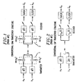
- FIGs. 1 and 2 Illustrative prior art transceiver structures for the QAM and CAP transmission schemes are shown in FIGs. 1 and 2 , respectively.
- g(t) e.g., see FIG.
- e in (t) and e qu (t) are equalizers for the in-phase and quadrature components, respectively
- p(t) and p ⁇ ( t ) are impulse responses of a shaping filter which form a Hilbert pair (e.g., see FIG. 2 ).
- the conventional QAM transceiver structure requires a modulator 1 and a demodulator 2 at the transmitter and receiver, respectively.
- the CAP transceiver of FIG. 2 does not require a modulator and a demodulator.
- the CAP system of FIG. 2 is not compatible with the QAM system of FIG. 1 , but provides the same theoretical performance as QAM and is simpler to implement digitally than QAM.
- the CAP structure of FIG. 2 can be modified into a simpler QAM-only transceiver, which is shown in FIG. 3 .
- VDSL Very high rate Digital Subscriber Line
- VDSL Very high rate Digital Subscriber Line
- Some in the art have proposed simply putting both the CAP receiver and the QAM receiver into one receiver - in effect having a dual structure receiver with a CAP section (having its own equalizer) and a separate QAM section (with its own equalizer).
- this dual structure receiver may require the use of blind equalization techniques in both the QAM section and the CAP section.
- the dual structure receiver must first independently converge both the equalizer in the QAM section and the equalizer in the CAP section, and then make a decision as to the type of modulation - all of which may cause significant timing overhead.
- European Patent Application EP 0 756 404 A2 discloses an adaptive equalizer having a digital filter including filter tap coefficients, a slicer, and a filter tap coefficient block. They are configured so as to perform at least one bust update of the filter tap coefficients.
- a receiver comprises an adaptive filter.
- the same blind equalization updating algorithm is used independent of the type of received signal.
- the blind equalization updating algorithm incorporates a constant R , whose value is a function of the type of received signal, e.g., a QAM signal or a CAP signal.
- the type of received signal is determined as a function of the in-phase component of the mean-squared error, E e n 2 . As such, this receiver can be started blindly without knowing whether the received signal is a QAM signal or a CAP signal.
- FIG. 4 An illustrative high-level block diagram of a portion of a communications system embodying the principles of the invention is shown in FIG. 4 .
- receiver 10 receives either a CAP signal or a QAM signal. It is assumed that the CAP or QAM signal has been distorted while propagating through communications channel 9 and experiences intersymbol interference (ISI). The purpose of receiver 10 is to remove the ISI and minimize the effect of any additive noise ⁇ ( t ) to provide signal r'(t) .
- ISI intersymbol interference
- the inventive concept will illustratively be described in the context of a receiver that has a dual mode of operation - a CAP mode and a QAM mode - that utilizes only a single equalizer for both the CAP mode of operation and the QAM mode of operation.
- an adaptive filter is, e.g., a fractionally spaced linear equalizer, which is hereafter simply referred to as an FSLE or, simply, an equalizer.
- the term "single equalizer structure” encompasses an adaptive filter for equalizing a received signal. As known in the art, this equalizer structure, or adaptive filter, itself may comprise other filters for different components, or combinations, of the received signal.
- a "single equalizer structure” is a cross-coupled equalizer, which comprises four filters, or a phase-splitting equalizer, which comprises two filters, etc.
- FSLE equalizer 100 operates on an input signal that can be characterized as having N dimensions.
- N 2, i.e., the input signal comprises two component dimensions: an in-phase component and a quadrature component.
- channel is also used herein to refer to each dimension, e.g., the in-phase dimension is also referred to as the in-phase channel.
- FIR finite impulse response
- Equalizer 100 is called a "phase-splitting FSLE" because the two FIR filters 110 and 120 converge to in-phase and quadrature filters.
- the two FIR filters 110 and 120 share the same tapped delay line 115, which stores sequences of successive Analog-to-Digital Converter (A/D) 125 samples r k .
- the outputs of the two adaptive FIR filters 110 and 120 as shown in FIG. 6 are computed at the symbol rate I / T .
- the equalizer taps and input samples can be represented by a corresponding N-dimensional vector.
- c n T c 0 ⁇ c 1. ⁇ c 2.
- ⁇ c N . vector of in - phase tap coefficients , and
- d n T d 0 ⁇ d 1. ⁇ d 2.
- FSLE equalizer 100 can be characterized as having two modes of operation, a normal mode (steady state) and a start-up mode (non-steady state).
- LMS least-mean-square
- the start-up mode is used to converge the tap coefficient values to an initial set of values.
- a training sequence is used during start-up (i.e., a predefined sequence of A n symbols), from which the receiver can compute meaningful errors E n by using the equalizer output signal Y n and the known sequence of transmitted symbols A n .
- tap adaptation is said to be done with respect to an "ideal reference.”
- equalizer 100 has to be converged blindly. This usually comprises two main steps. First, a blind equalization algorithm is used to open the "eye diagram. " Then, once the eye is open enough, the receiver switches to, e.g., the above-described LMS tap adaptation algorithm.
- the philosophy of blind equalization is to use a tap adaptation algorithm that minimizes a cost function that is better suited to provide initial convergence of equalizer 100 than the MSE represented by equation (7).
- MMA multimodulus algorithm
- MMA algorithm is well suited to applications using two-dimensional transmission schemes such as CAP and QAM, and discusses some of the advantages provided by MMA compared to other blind equalization algorithms such as the reduced constellation algorithm and the constant modulus algorithm.
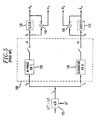
- FIG. 7 a portion 200 of a dual-mode receiver for CAP and QAM, such as receiver 10 of FIG. 4 , (also referred to herein as a CAP-QAM receiver) is shown in FIG. 7 .
- CAP-QAM receiver portion the elements shown in FIG. 7 are well-known and will not be described in detail.
- CAP-QAM receiver portion 200 comprises rotator 215, filter updating elements 220 and 225, slicers 230 and 235, element 240, and a single phase-splitting FSLE as represented by FIR filters 205 and 210.
- CAP-QAM receiver portion 200 illustrates the tap updating of FIR filters 205 and 210.
- filter updating elements 220 and 225 of FIG. 7 As can be observed from filter updating elements 220 and 225 of FIG. 7 , CAP-QAM receiver portion 200 uses the same filter updating algorithm independent of the type of received signal.
- the MMA blind equalization algorithm is used.
- the inventive concept is not so limited and other forms of blind equalization can be used, such as, but not limited to, RCA and CMA (described below).
- the value of the constant R (shown in filter updating elements 220 and 225, and described further below) is adjusted as a function of the type of received signal. As such, this receiver can be started blindly without knowing whether the received signal is a QAM signal or a CAP signal.
- FIG. 8 shows an illustrative flow diagram of a method embodying the principles of the invention for use in a CAP-QAM receiver, such as the structure of FIG. 7 .
- the receiver initially starts in the CAP mode of operation.
- a variable, S( ⁇ ) is set equal to zero and the value for the constant R is initially set to R C (described below).
- a decision is made as to whether a CAP signal or a QAM signal is being received by comparing the corresponding in-phase component of the mean-squared error, E e n 2 , to a predetermined MSE value, M (which is determined experimentally and depends upon the signal constellation).
- Step 510 of the blind start-up procedure can be schedule-driven, event-driven, or both.
- a schedule-driven approach occurs after some fixed number, Z , of iterations (which can be determined by a counter, for example). If the value of E e n 2 is larger than the value of M then it is assumed that a QAM signal is being received and execution proceeds to steps 515 and 520.
- a variable S( ⁇ ) is set equal to one, and, in step 520, the value of R is set equal to R Q (described below).
- step 545 the variable, S( ⁇ ), is set equal to zero.
- step 550 the value of R is set equal to R C (described below).
- a variable, S( ⁇ ) is either set to zero or one. This variable controls the operation of rotator 225 of FIG. 7 .
- output signal Y n i.e., Y n ⁇ is equal to Y n .
- the in-phase error, e n is equal to y n - â n .
- the in-phase error, e n is equal to y n ⁇ - a ⁇ n .
- filter updating elements 220 and 225 of FIG. 7 use the same filter updating algorithm (here, illustratively MMA-based) independent of the type of received signal.
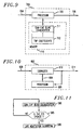
- FIG. 9 illustrates an embodiment representative of a digital signal processor 700 that is programmed to implement an FSLE in accordance with the principles of the invention.
- Digital signal processor 700 comprises a central processing unit (processor) 705 and memory 710.
- a portion of memory 710 is used to store program instructions that, when executed by processor 705, implement CAP-QAM blind equalization (described above). This portion of memory is shown as 711.
- Another portion of memory, 712 is used to store tap coefficient values that are updated by processor 705 in accordance with the inventive concept.
- a received signal 704 is applied to processor 705, which equalizes this signal in accordance with the inventive concept to provide a output signal 706.
- output signal 706 represents a sequence of output samples of an equalizer.
- a digital signal processor may, additionally, further process received signal 704 before deriving output signal 706.
- An illustrative software program is not described herein since, after learning of the CAP-QAM blind equalization as described herein, such a program is within the capability of one skilled in the art.
- any equalizer structures can be implemented by digital signal processor 700 in accordance with the inventive concept.
- FIG. 10 illustrates another alternative embodiment of the inventive concept.
- Circuitry 600 comprises a central processing unit (processor) 605, and an equalizer 610.
- the latter is illustratively assumed to be a phase-splitting FSLE as described above.
- equalizer 610 includes at least one tap-coefficient register for storing values for corresponding tap coefficient vectors (e.g., as shown in FIG. 6 ).
- Processor 605 includes memory, not shown, similar to memory 710 of FIG. 9 for implementing CAP-QAM blind equalization.
- Equalizer output signal 611 which represents a sequence of equalizer output samples, is applied to processor 605. The latter analyzes equalizer output signal 611, in accordance with the inventive concept, to adapt values of the tap coefficients in such a way as to converge to a correct solution.
- a blind start-up procedure in accordance with the principles of the invention for use in receiver 10 of FIG. 4 is shown in FIG. 11 .
- receiver 10 uses CAP-QAM blind equalization with its corresponding tap updating algorithms to begin blind convergence of an equalizer, e.g., steps 505 to 525 of FIG. 8 and equalizer 610 of FIG. 10 .
- a decision is made whether to switch from CAP-QAM blind equalization to the LMS adaptation algorithm or to continue using CAP-QAM blind equalization to converge the equalizer. Typically, this is referred to in the art as determining if the eye is open enough (as noted above).
- Step 585 of the blind start-up procedure can be schedule-driven, event-driven, or both.
- the switch between two different tap updating algorithms occurs after some fixed number, K, of iterations (which can be determined by a counter, for example). This approach presumes a certain amount of eye-opening after K iterations.
- K the number of iterations
- the switch occurs when a certain quality of eye opening is achieved. This can be done, for example, by continuously monitoring the MSE and making the switch when the MSE is below some threshold S . If the eye has been opened enough, receiver 10 switches to the LMS Adaptation algorithm in step 590.
- the focus of the inventive concept is the use of a single equalizer during blind start-up. As such, once the transition to the LMS algorithm occurs, further updates occur as known in the art. For example, in the QAM mode of operation, an additional rotator may have to be used when updating the equalizer using LMS.
- the value of the constant R (shown in filter updating elements 220 and 225) is adjusted as a function of the type of received signal.
- R is also affected by what type of blind equalization method is being used. Below, values for R are given for the CMA, MMA, and RCA, blind equalization algorithms. (Additional information on these blind equalization algorithms can be found in the above-cited articles.)
- the cost function in equation (18) is a true two-dimensional cost function which minimizes the dispersion of the equalizer complex output signal Y n with respect to a circle with radius R.
- the CAP-QAM dual mode receiver has the same filter updating algorithm as that of a CAP-only equalizer.
- L 2 .
- the MMA algorithm was used in the illustrative example of FIG. 7 .
- the MMA algorithm minimizes the dispersion of the equalizer output samples y n and ⁇ n around piecewise linear in-phase and quadrature contours.
- equation (22) is not a true two-dimensional cost function. Rather, it is the sum of two independent one-dimensional cost functions CF , and CF q .
- the constant R can be numerically computed from equation (25). However, the constant R can also be expressed as a function of the number m of symbol levels.
- the CAP-QAM receiver for RCA is similar to the one for MMA.
- R C E a n 2 E a n .
- Equation (30) can be simplified to E a n 2 .
- R Q 2.6 .
Landscapes
- Engineering & Computer Science (AREA)
- Computer Networks & Wireless Communication (AREA)
- Signal Processing (AREA)
- Power Engineering (AREA)
- Physics & Mathematics (AREA)
- Spectroscopy & Molecular Physics (AREA)
- Digital Transmission Methods That Use Modulated Carrier Waves (AREA)
- Cable Transmission Systems, Equalization Of Radio And Reduction Of Echo (AREA)
- Filters That Use Time-Delay Elements (AREA)
Claims (16)
- Vorrichtung zum Empfang eines trägerlosen Amplitudenmodulations-/Phasenmodulationssignals (CAP) oder eines Quadraturamplituden/Phasenmodulationssignals (QAM), wobei die Vorrichtung gekennzeichnet ist durch:Einen Empfänger (200) mit einem dualen Betriebsmodus, einem CAP-Modus und einem QAM-Modus, welcher nur einen Entzerrer für sowohl den CAP-Betriebsmodus als auch den QAM-Betriebsmodus verwendet;wobei der Entzerrer über einen zugeordneten Satz von Abgriff-Koeffizienten verfügt, wobei derselbe Entzerrungsaktualisierungsalgorithmus sowohl im CAP-Betriebsmodus als auch im QAM-Betriebsmodus verwendet wird, und wobei der Entzerrungsaktualisierungsalgorithmus ein Blindentzerrungsalgorithmus mit einer Konstanten ist, deren Wert abhängig davon, ob sich der Empfänger im CAP-Betriebsmodus oder im QAM-Betriebsmodus befindet, ausgewählt wird.
- Ein Verfahren zur Anwendung in einem Empfänger, gekennzeichnet durch:Auswählen (200) von einem der Anzahl von Betriebsmoden für den Empfänger;Filtern (205, 210), anhand eines Filters, eines Signals, um ein gefiltertes Signal bereitzustellen; undAktualisieren (220, 225) der Koeffizienten des Filters unter Verwendung eines Blindentzerrungsalgorithmus, so dass mindestens ein konstanter Wert des Aktualisierungsalgorithmus in Abhängigkeit des Betriebsmodus des Empfängers ausgewählt wird;wobei die Anzahl der Betriebsmoden einen trägerlosen Amplitudenmodulations-/Phasenmodulationsmodus (CAP) und einen Quadraturamplituden/Phasenmodulationsmodus (QAM) umfasst.
- Vorrichtung nach Anspruch 1, wobei der Blindentzerrungsalgorithmus ein Algorithmus vom Typ konstanter Modulus oder vom Typ Multimodulus oder vom Typ reduzierte Konstellation ist.
- Vorrichtung nach Anspruch 1, wobei der Empfänger weiterhin einen Demodulator umfasst, welcher während des QAM-Betriebsmodus operativ ist, um ein Ausgangssignal des Entzerrers zu demodulieren.
- Vorrichtung nach Anspruch 1, wobei der Entzerrungsaktualisierungsalgorithmus eine Funktion von ỹn 2 - R2 ist, wobei der Wert der Konstanten R in Abhängigkeit davon, ob sich der Empfänger im CAP-Betriebsmodus oder im QAM-Betriebsmodus befindet, ausgewählt wird, und ỹn eine komplexe Komponente eines Ausgangs des Entzerrers ist.
- Das Verfahren nach Anspruch 2, wobei der Blindentzerrungsalgorithmus ein Algorithmus vom Typ konstanter Modulus oder vom Typ Multimodulus oder vom Typ reduzierte Konstellation ist.
- Vorrichtung nach Anspruch 1, wobei der Entzerrer weiterhin eine Doppelfilter-Struktur aufweist.
- Das Verfahren nach Anspruch 6, wobei der Entzerrungsaktualisierungsalgorithmus eine Funktion von ỹn 2 - R2 ist, wobei der Wert der Konstanten R in Abhängigkeit davon, ob sich der Empfänger im CAP-Betriebsmodus oder im QAM-Betriebsmodus befindet, ausgewählt wird, und ỹn eine komplexe Komponente eines Ausgangs des Entzerrers ist.
- Das Verfahren nach Anspruch 2, wobei der Schritt des Auswählens die folgenden Schritte umfasst:Ermitteln eines Fehlerwertes als eine Funktion des gefilterten Signals; undAuswählen des Betriebsmodus als eine Funktion des ermittelten Fehlerwertes.
- Das Verfahren nach Anspruch 9, wobei der ermittelte Fehlerwert als eine Funktion einer mittleren quadratischen Fehlerfunktion bestimmt wird.
- Das Verfahren nach Anspruch 9, wobei der Schritt des Auswählens des Modus den ermittelten Fehlerwert mit einem vorbestimmten Wert vergleicht, so dass, wenn der ermittelte Fehlerwert niedriger als der vorbestimmte Wert ist, ein Betriebsmodus ausgewählt wird; anderenfalls wird ein anderer Betriebsmodus ausgewählt.
- Das Verfahren nach Anspruch 2, weiterhin die folgenden Schritte umfassend:Bearbeiten des gefilterten Signals, um ein bearbeitetes Signal bereitzustellen, so dass die Bearbeitung in einem ersten Betriebsmodus das gefilterte Signal demoduliert, und die Bearbeitung in einem zweiten Betriebsmodus das gefilterte Signal durchlässt; und Abschneiden des bearbeiteten Signals, um ein abgeschnittenes Signal bereitzustellen.
- Das Verfahren nach Anspruch 12, wobei der Schritt des Auswählens den Schritt des Auswählens des Betriebsmodus als eine Funktion einer Differenz zwischen dem bearbeiteten Signal und dem abgeschnittenen Signal umfasst.
- Das Verfahren nach Anspruch 13, wobei der Schritt des Auswählens den Schritt des Auswählens des Betriebsmodus als eine Funktion eines mittleren quadratischen Fehlers einer Differenz zwischen dem bearbeiteten Signal und dem abgeschnittenen Signal umfasst.
- Das Verfahren nach Anspruch 14, wobei das bearbeitete Signal und das abgeschnittene Signal weiterhin eine Inphasekomponente und eine Quadraturkomponente umfassen.
- Das Verfahren nach Anspruch 15, wobei sich die Differenz zwischen den Inphasekomponenten der jeweiligen Signale befindet.
Applications Claiming Priority (2)
| Application Number | Priority Date | Filing Date | Title |
|---|---|---|---|
| US09/109,364 US6252903B1 (en) | 1998-07-02 | 1998-07-02 | Blind start-up of a dual mode CAP-QAM receiver |
| US109364 | 1998-07-02 |
Publications (3)
| Publication Number | Publication Date |
|---|---|
| EP0969635A2 EP0969635A2 (de) | 2000-01-05 |
| EP0969635A3 EP0969635A3 (de) | 2002-10-02 |
| EP0969635B1 true EP0969635B1 (de) | 2009-03-25 |
Family
ID=22327267
Family Applications (1)
| Application Number | Title | Priority Date | Filing Date |
|---|---|---|---|
| EP99304913A Expired - Lifetime EP0969635B1 (de) | 1998-07-02 | 1999-06-23 | Blindentzerrung in Empfängern mit sowohl CAP- als auch QAM-Betriebsmoden |
Country Status (6)
| Country | Link |
|---|---|
| US (1) | US6252903B1 (de) |
| EP (1) | EP0969635B1 (de) |
| JP (1) | JP2000083072A (de) |
| CA (1) | CA2272246A1 (de) |
| DE (1) | DE69940626D1 (de) |
| TW (1) | TW437215B (de) |
Families Citing this family (9)
| Publication number | Priority date | Publication date | Assignee | Title |
|---|---|---|---|---|
| EP0963085A1 (de) * | 1998-06-04 | 1999-12-08 | Siemens Aktiengesellschaft | Verfahren zur adaptiven Filtereinstellung in einem QAM/CAP-System |
| US6493381B1 (en) * | 1999-06-24 | 2002-12-10 | Agere Systems Inc. | Blind equalization algorithm with the joint use of the constant R and the sliced symbols |
| US6856655B1 (en) * | 1999-12-21 | 2005-02-15 | Texas Instruments Incorporated | Timing recovery device and method for telecommunications systems |
| BRPI0101198B1 (pt) * | 2001-03-02 | 2015-09-01 | Unicamp | Processo concorrente para desconvolução autodidata de sinais digitais |
| JP4373330B2 (ja) * | 2002-07-18 | 2009-11-25 | クゥアルコム・インコーポレイテッド | ハイブリッド判定フィードバック・イコライゼーションに関する方法及び装置 |
| US8913901B2 (en) | 2012-02-20 | 2014-12-16 | Tyco Electronics Subsea Communications Llc | System and method for blind equalization and carrier phase recovery in a quadrature amplitude modulated system |
| US9559875B2 (en) * | 2012-05-09 | 2017-01-31 | Northrop Grumman Systems Corporation | Blind equalization in a single carrier wideband channel |
| CN117352034A (zh) | 2022-06-29 | 2024-01-05 | 长鑫存储技术有限公司 | 数据输入校验方法及数据输入校验结构 |
| CN116260693B (zh) * | 2023-02-20 | 2025-10-17 | 北京邮电大学 | 一种基于预均衡的超高阶qam调制传输系统和方法 |
Family Cites Families (5)
| Publication number | Priority date | Publication date | Assignee | Title |
|---|---|---|---|---|
| US5673293A (en) * | 1994-09-08 | 1997-09-30 | Hitachi America, Ltd. | Method and apparatus for demodulating QAM and VSB signals |
| US5646957A (en) * | 1995-07-28 | 1997-07-08 | Lucent Technologies Inc. | Burst update for an adaptive equalizer |
| US5799037A (en) * | 1996-02-16 | 1998-08-25 | David Sarnoff Research Center Inc. | Receiver capable of demodulating multiple digital modulation formats |
| US5930309A (en) * | 1997-02-27 | 1999-07-27 | Thomson Consumer Electronics, Inc. | Receiver signal processing system for cap signals |
| JP3886160B2 (ja) * | 1996-10-11 | 2007-02-28 | トムソン コンシユーマ エレクトロニクス インコーポレイテツド | Cap信号処理用受信機およびcap信号を受信する方法 |
-
1998
- 1998-07-02 US US09/109,364 patent/US6252903B1/en not_active Expired - Lifetime
-
1999
- 1999-05-18 CA CA002272246A patent/CA2272246A1/en not_active Abandoned
- 1999-05-21 TW TW088108385A patent/TW437215B/zh not_active IP Right Cessation
- 1999-06-23 EP EP99304913A patent/EP0969635B1/de not_active Expired - Lifetime
- 1999-06-23 DE DE69940626T patent/DE69940626D1/de not_active Expired - Lifetime
- 1999-07-02 JP JP11188298A patent/JP2000083072A/ja active Pending
Also Published As
| Publication number | Publication date |
|---|---|
| JP2000083072A (ja) | 2000-03-21 |
| CA2272246A1 (en) | 2000-01-02 |
| EP0969635A2 (de) | 2000-01-05 |
| TW437215B (en) | 2001-05-28 |
| US6252903B1 (en) | 2001-06-26 |
| DE69940626D1 (de) | 2009-05-07 |
| EP0969635A3 (de) | 2002-10-02 |
Similar Documents
| Publication | Publication Date | Title |
|---|---|---|
| US6490318B1 (en) | Phase-compensating constant modulus algorithm | |
| US6069917A (en) | Blind training of a decision feedback equalizer | |
| EP0845891B1 (de) | Fenstertechnik für blinde Entzerrung | |
| Ready et al. | Blind equalization based on radius directed adaptation | |
| KR100259317B1 (ko) | 2-필터 적응 등화기의 블라인드 수렴을 향상시키기 위한 방법및 장치 | |
| KR100289169B1 (ko) | 전환알고리즘을이용한적응등화기의블라인드수렴을향상시키기위한방법및장치 | |
| US6259743B1 (en) | Automatic constellation phase recovery in blind start-up of a dual mode CAP-QAM receiver | |
| US6314134B1 (en) | Blind equalization algorithm with joint use of the constant modulus algorithm and the multimodulus algorithm | |
| Oh et al. | New blind equalization techniques based on constant modulus algorithm | |
| US5940440A (en) | Generalized multimodulus technique for blind equalization | |
| EP0969635B1 (de) | Blindentzerrung in Empfängern mit sowohl CAP- als auch QAM-Betriebsmoden | |
| CA2200139C (en) | Multimodulus blind equalization using piecewise linear contours | |
| EP1063822B1 (de) | Algorithmus zur blinden Entzerrung unter Verwendung von sowohl der Konstanten R als auch von den entschiedenen Symbolen | |
| MXPA97004115A (en) | Multimodal equalizer in a digi video signal processing system |
Legal Events
| Date | Code | Title | Description |
|---|---|---|---|
| PUAI | Public reference made under article 153(3) epc to a published international application that has entered the european phase |
Free format text: ORIGINAL CODE: 0009012 |
|
| AK | Designated contracting states |
Kind code of ref document: A2 Designated state(s): AT BE CH CY DE DK ES FI FR GB GR IE IT LI LU MC NL PT SE |
|
| AX | Request for extension of the european patent |
Free format text: AL;LT;LV;MK;RO;SI |
|
| PUAL | Search report despatched |
Free format text: ORIGINAL CODE: 0009013 |
|
| AK | Designated contracting states |
Kind code of ref document: A3 Designated state(s): AT BE CH CY DE DK ES FI FR GB GR IE IT LI LU MC NL PT SE |
|
| AX | Request for extension of the european patent |
Free format text: AL;LT;LV;MK;RO;SI |
|
| 17P | Request for examination filed |
Effective date: 20030324 |
|
| AKX | Designation fees paid |
Designated state(s): DE FR GB |
|
| GRAP | Despatch of communication of intention to grant a patent |
Free format text: ORIGINAL CODE: EPIDOSNIGR1 |
|
| GRAS | Grant fee paid |
Free format text: ORIGINAL CODE: EPIDOSNIGR3 |
|
| GRAA | (expected) grant |
Free format text: ORIGINAL CODE: 0009210 |
|
| AK | Designated contracting states |
Kind code of ref document: B1 Designated state(s): DE FR GB |
|
| REG | Reference to a national code |
Ref country code: GB Ref legal event code: FG4D |
|
| REF | Corresponds to: |
Ref document number: 69940626 Country of ref document: DE Date of ref document: 20090507 Kind code of ref document: P |
|
| RAP4 | Party data changed (patent owner data changed or rights of a patent transferred) |
Owner name: LUCENT TECHNOLOGIES INC. |
|
| PLBE | No opposition filed within time limit |
Free format text: ORIGINAL CODE: 0009261 |
|
| STAA | Information on the status of an ep patent application or granted ep patent |
Free format text: STATUS: NO OPPOSITION FILED WITHIN TIME LIMIT |
|
| 26N | No opposition filed |
Effective date: 20091229 |
|
| REG | Reference to a national code |
Ref country code: GB Ref legal event code: 732E Free format text: REGISTERED BETWEEN 20131031 AND 20131106 |
|
| REG | Reference to a national code |
Ref country code: FR Ref legal event code: CD Owner name: ALCATEL-LUCENT USA INC. Effective date: 20131122 |
|
| REG | Reference to a national code |
Ref country code: FR Ref legal event code: GC Effective date: 20140410 |
|
| REG | Reference to a national code |
Ref country code: FR Ref legal event code: RG Effective date: 20141015 |
|
| REG | Reference to a national code |
Ref country code: FR Ref legal event code: PLFP Year of fee payment: 17 |
|
| PGFP | Annual fee paid to national office [announced via postgrant information from national office to epo] |
Ref country code: GB Payment date: 20150618 Year of fee payment: 17 Ref country code: DE Payment date: 20150619 Year of fee payment: 17 |
|
| PGFP | Annual fee paid to national office [announced via postgrant information from national office to epo] |
Ref country code: FR Payment date: 20150619 Year of fee payment: 17 |
|
| REG | Reference to a national code |
Ref country code: DE Ref legal event code: R119 Ref document number: 69940626 Country of ref document: DE |
|
| GBPC | Gb: european patent ceased through non-payment of renewal fee |
Effective date: 20160623 |
|
| REG | Reference to a national code |
Ref country code: FR Ref legal event code: ST Effective date: 20170228 |
|
| PG25 | Lapsed in a contracting state [announced via postgrant information from national office to epo] |
Ref country code: FR Free format text: LAPSE BECAUSE OF NON-PAYMENT OF DUE FEES Effective date: 20160630 Ref country code: DE Free format text: LAPSE BECAUSE OF NON-PAYMENT OF DUE FEES Effective date: 20170103 |
|
| PG25 | Lapsed in a contracting state [announced via postgrant information from national office to epo] |
Ref country code: GB Free format text: LAPSE BECAUSE OF NON-PAYMENT OF DUE FEES Effective date: 20160623 |