EP0970622A2 - Vorrichtung und Verfahren zur Lebensmittelbehandlung - Google Patents
Vorrichtung und Verfahren zur Lebensmittelbehandlung Download PDFInfo
- Publication number
- EP0970622A2 EP0970622A2 EP99113166A EP99113166A EP0970622A2 EP 0970622 A2 EP0970622 A2 EP 0970622A2 EP 99113166 A EP99113166 A EP 99113166A EP 99113166 A EP99113166 A EP 99113166A EP 0970622 A2 EP0970622 A2 EP 0970622A2
- Authority
- EP
- European Patent Office
- Prior art keywords
- food
- flow
- liquid
- treating surface
- swinging
- Prior art date
- Legal status (The legal status is an assumption and is not a legal conclusion. Google has not performed a legal analysis and makes no representation as to the accuracy of the status listed.)
- Withdrawn
Links
- 235000013305 food Nutrition 0.000 title claims abstract description 190
- 238000000034 method Methods 0.000 title claims abstract description 16
- 230000008569 process Effects 0.000 title claims abstract description 15
- 239000000356 contaminant Substances 0.000 claims abstract description 79
- 239000000835 fiber Substances 0.000 claims abstract description 37
- 239000000203 mixture Substances 0.000 claims abstract description 32
- 239000007788 liquid Substances 0.000 claims description 66
- 230000007246 mechanism Effects 0.000 claims description 33
- 238000000638 solvent extraction Methods 0.000 claims description 12
- 238000005273 aeration Methods 0.000 claims description 9
- 239000000463 material Substances 0.000 claims description 9
- 210000004209 hair Anatomy 0.000 description 28
- 230000000694 effects Effects 0.000 description 17
- XLYOFNOQVPJJNP-UHFFFAOYSA-N water Substances O XLYOFNOQVPJJNP-UHFFFAOYSA-N 0.000 description 13
- 238000005406 washing Methods 0.000 description 10
- 238000000926 separation method Methods 0.000 description 8
- 238000011144 upstream manufacturing Methods 0.000 description 8
- 238000005507 spraying Methods 0.000 description 6
- 238000013019 agitation Methods 0.000 description 5
- 238000004140 cleaning Methods 0.000 description 3
- 238000007599 discharging Methods 0.000 description 3
- 239000002184 metal Substances 0.000 description 3
- 239000007787 solid Substances 0.000 description 3
- 240000008067 Cucumis sativus Species 0.000 description 2
- 235000009849 Cucumis sativus Nutrition 0.000 description 2
- 244000124853 Perilla frutescens Species 0.000 description 2
- 235000016374 Perilla frutescens var crispa Nutrition 0.000 description 2
- 235000015640 Perilla frutescens var frutescens Nutrition 0.000 description 2
- 230000002349 favourable effect Effects 0.000 description 2
- 239000012530 fluid Substances 0.000 description 2
- 238000004080 punching Methods 0.000 description 2
- 229920005989 resin Polymers 0.000 description 2
- 239000011347 resin Substances 0.000 description 2
- 238000005096 rolling process Methods 0.000 description 2
- 150000003839 salts Chemical class 0.000 description 2
- 240000001949 Taraxacum officinale Species 0.000 description 1
- 235000005187 Taraxacum officinale ssp. officinale Nutrition 0.000 description 1
- 235000009508 confectionery Nutrition 0.000 description 1
- 230000008878 coupling Effects 0.000 description 1
- 238000010168 coupling process Methods 0.000 description 1
- 238000005859 coupling reaction Methods 0.000 description 1
- 239000000428 dust Substances 0.000 description 1
- 235000013399 edible fruits Nutrition 0.000 description 1
- 230000005484 gravity Effects 0.000 description 1
- 238000011835 investigation Methods 0.000 description 1
- 238000012986 modification Methods 0.000 description 1
- 230000004048 modification Effects 0.000 description 1
- 230000002093 peripheral effect Effects 0.000 description 1
- 235000021067 refined food Nutrition 0.000 description 1
- 230000002195 synergetic effect Effects 0.000 description 1
- 229920003002 synthetic resin Polymers 0.000 description 1
- 239000000057 synthetic resin Substances 0.000 description 1
- 235000013311 vegetables Nutrition 0.000 description 1
Images






Classifications
-
- A—HUMAN NECESSITIES
- A23—FOODS OR FOODSTUFFS; TREATMENT THEREOF, NOT COVERED BY OTHER CLASSES
- A23N—MACHINES OR APPARATUS FOR TREATING HARVESTED FRUIT, VEGETABLES OR FLOWER BULBS IN BULK, NOT OTHERWISE PROVIDED FOR; PEELING VEGETABLES OR FRUIT IN BULK; APPARATUS FOR PREPARING ANIMAL FEEDING- STUFFS
- A23N12/00—Machines for cleaning, blanching, drying or roasting fruits or vegetables, e.g. coffee, cocoa, nuts
- A23N12/005—Machines for cleaning, blanching, drying or roasting fruits or vegetables, e.g. coffee, cocoa, nuts for dry-cleaning
-
- Y—GENERAL TAGGING OF NEW TECHNOLOGICAL DEVELOPMENTS; GENERAL TAGGING OF CROSS-SECTIONAL TECHNOLOGIES SPANNING OVER SEVERAL SECTIONS OF THE IPC; TECHNICAL SUBJECTS COVERED BY FORMER USPC CROSS-REFERENCE ART COLLECTIONS [XRACs] AND DIGESTS
- Y02—TECHNOLOGIES OR APPLICATIONS FOR MITIGATION OR ADAPTATION AGAINST CLIMATE CHANGE
- Y02A—TECHNOLOGIES FOR ADAPTATION TO CLIMATE CHANGE
- Y02A40/00—Adaptation technologies in agriculture, forestry, livestock or agroalimentary production
- Y02A40/90—Adaptation technologies in agriculture, forestry, livestock or agroalimentary production in food processing or handling, e.g. food conservation
Definitions
- the present invention relates to an apparatus for food treatment comprising fiber removing means for removing fibrous contaminants such as hairs, lint, and the like included in food such as vegetables, fruit, confectionery, processed food, or a food mixture made by mixing the above food into liquid or the like.
- the invention also relates to a process for food treatment using the apparatus for food treatment.
- an apparatus for food treatment having fiber removing means there is known an apparatus which has a plurality of rolls densely implanted on surfaces thereof with a large number of straight or substantially straight hairs, herein referred to as straight hairs, and which removes fibrous contaminants by rotating the rolls to bring the fibrous contaminants in contact with the rolls to be tangled with the hairs on the rolls.
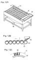
- FIGS. 12A to 12C An example of such an apparatus is shown in FIGS. 12A to 12C, in which FIG. 12A is a general view, FIG. 12B is an explanatory view of an operation, and FIG. 12C shows an enlarged view of the roll.
- a plurality of hair-implanted rolls 51 formed by densely implanting straight hairs 52 with short lengths of about 5 to 10 mm on rolls 53 are arranged substantially horizontally without a clearance therebetween.
- the hair-implanted rolls 51 can be rotated in the same direction, a driving mechanism is not shown, and a plurality of sprinkling pipes 54 for sprinkling from above the hair-implanted rolls 51 to facilitate separation of the contaminants are provided.
- food 1 supplied from a supply portion 55 is carried to the downstream side while coming into contact with the straight hairs 52 on the surfaces of the hair-implanted rolls 51 and rolling by rotation of the hair-implanted rolls 51, see FIG. 12B.
- the implanted hairs are straight, the implanted hairs cannot exhibit a function of sufficiently tangling with and catching the fibrous contaminants when the fibrous contaminants come into contact with the implanted hairs. In other words, before the implanted hairs tangle with and catch the fibrous contaminant, the fibrous contaminants separate from the implanted hair. Therefore, the efficiency of removing the fibrous contaminants is low. In another case, the fibrous contaminant, which has once adhered to the implanted hair, separates from the implanted hair and adheres to the food again.
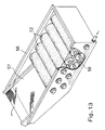
- FIG. 13 there is another apparatus in which a plurality of hair-implanted rolls 52 similar to those in the apparatus shown in FIGS. 12A to 12C are arranged in a zigzag manner at a distance from each other in a washing tank 58 for storing liquid, and lower portion air spraying pipes 59 are disposed below the hair-implanted rolls 52 as shown in FIG. 13.
- the hair-implanted rolls 52 are rotated to scatter the food 1 in liquid such as water and salt water (a food mixture), the fibrous contaminants are liberated into the liquid by vibration and convection generated by aeration from the lower portion air spraying pipes 59, and the fibrous contaminants are tangled with and caught by the hair-implanted rolls 52.
- the treated food mixture is carried and discharged while being separated into solids and liquid by a screen conveyer 57 or the like provided on the downstream side thereof.
- the implanted hairs cannot exhibit a function of sufficiently tangle with and catch the fibrous contaminants when the fibrous contaminants come into contact with the implanted hairs, because the implanted hairs are straight.
- this object has been solved in an advantageous and satisfying manner.
- the present inventors have found that a treating surface on which a plurality of hooks are formed to stand and especially a treating surface formed with hook parts of hook-and-loop fasteners are effective at removing fibrous contaminants. Hence, the present invention was completed after various studies.
- the apparatus for food treatment comprises fiber removing means for removing fibrous contaminants included in food or food mixtures, and the fiber removing means have a treating surface on which a plurality of hooks are formed to stand and which are disposed to come into contact with the food or the food mixture.
- the apparatus does not employ the conventional plurality of straight hairs to catch the fibrous contaminants therebetween, it is unnecessary to densely form a large number of standing hooks.
- the apparatus is advantageous in respect of costs and the fibrous contaminants are less prone to fall off due to an external force. As a result, the fibrous contaminants included in food or the like can be removed more completely.
- the hooks are preferably made of flexible material.
- the hooks are flexible, the hooks are deformed flexibly and come into contact with food or the like efficiently. Because there is the possibility that the orientation of the respective hooks is changed such that the hooks catch the fibrous contaminants in a deformation process of the hooks, the effect of removing the fibrous contaminants is further enhanced. Because the hooks are flexible, the hooks are less prone to damage the food.
- the fiber removing means preferably have the treating surface formed of the hook parts of the hook-and-loop fasteners with cut loops.
- the fibrous contaminants can be removed more completely.
- the hooks are disposed in different orientations on the above hook-and-loop fasteners in general in such a manner that the hooks can easily be engaged with loops of a loop part. Therefore, chances to catch the fibrous contaminants are increased.
- the hook-and-loop fasteners are easy to get and are advantageous in respect of costs, and the treating surfaces can be easily changed.
- the fiber removing means have a trough the longitudinal direction of which is inclined from a horizontal plane and which is supported for a swinging movement with a swinging axial center mostly in parallel to the longitudinal direction. Also, a swinging movement applying mechanism is provided for reciprocating and swinging the trough from a reference position of the trough where the width direction of the trough is substantially horizontal. Also, the trough is provided at a bottom face thereof with the treating surface.
- the food or the like supplied from the upper side of the inclination can roll down in a zigzag manner, thereby obtaining the above-described acts and effects while improving the efficiency of the contact between the treating surface and the food or the like.
- the fibrous contaminants are separated from the food or the like, while the food or the like is rolling, the fibrous contaminants are not strained in the separation and are less prone to be cut off so that the apparatus is also effective to long fibrous contaminants such as hairs. Because the food or the like is moved and agitated not so vigorously as compared with other embodiments, the apparatus is suitable for food or the like which is liable to loose its shape or is small in size.
- the fiber removing means have a vibration applying mechanism for applying vibration to a placing face on which the food or the food mixture is placed, and the placing face is provided with the treating surface.
- the vibration applying mechanism for applying vibration to a placing face on which the food or the food mixture is placed, and the placing face is provided with the treating surface.
- the fiber removing means have a plurality of rolls which are provided at surfaces thereof with the treating surfaces and which are disposed substantially close to each other, wherein a rotation driving means is provided for rotating the rolls in the same direction.
- rotation of the rolls and carriage of the food or the like can be controlled separately from each other.
- the fiber removing means have a pipe-shaped body provided at the inner face thereof with the treating surface and rotatably supported in a state in which the pipe-shaped body is inclined with respect to the horizontal plane, and a rotation driving mechanism is provided for rotating the pipe-shaped body.
- the food drops while being raked up by rotation of the inner wall of the pipe-shaped body.
- the food is agitated vigorously and repeatedly brought into intimate contact with the treating surface. Therefore, the fibrous contaminants can be caught efficiently.
- the treating surface can easily be designed to be large, the apparatus has a wide range of applications.
- the food mixture can be a liquid including food, wherein the fiber removing means have a flow tank for causing the liquid to flow; a flow controlling plate is provided for causing the liquid to flow non-linearly in the flow tank, and the flow controlling plate is provided with the treating surface.
- the fiber removing means have a flow tank for causing the liquid to flow; a flow controlling plate is provided for causing the liquid to flow non-linearly in the flow tank, and the flow controlling plate is provided with the treating surface.
- the food mixture can be liquid including food
- the fiber removing means have a flow tank for causing the liquid to flow, an agitating plate for causing the liquid to flow non-linearly in the flow tank, and a driving mechanism for driving the agitating plate, wherein the agitating plate is provided with the treating surface.
- the food mixture can be liquid including food
- the fiber removing means comprise a flow tank which is partitioned into upper and lower portions by a partitioning plate having a tendency to prevent the food from passing therethrough and which causes the food to flow on the upper side of the partitioning plate by causing the liquid to flow.
- An agitating plate is provided for swinging from a reference position thereof where the agitating plate is vertical to or inclined with respect to a liquid level with a swinging axial center substantially in parallel to a flow direction of the flow tank.
- a driving mechanism is provided for reciprocating and swinging the agitating plate.
- aeration means are provided which are disposed on the lower side of or in the vicinity of the partitioning plate below the agitating plate and which have a releasing outlet for releasing gas into the liquid; the agitating plate is provided with the treating surface.
- a process for food treatment of the invention which is suitable for removing fibrous contaminants included in food or a food mixture, which method comprises the step of bringing a treating surface, on which a plurality of hooks are formed to stand, into contact with the food or the food mixture. According to the process for food treatment according to the invention, it is by the above-described effects that the fibrous contaminants included in the food can be removed more completely and efficiently.
- An apparatus for food treatment of the invention includes a food washing apparatus comprising only a fiber removing means, a food washing apparatus having another washing means, and an apparatus for food treatment or the like combined with a dryer, a heater, a mixer, a sterilizer or the like other than the washing means.
- the apparatus for food treatment of the invention is an apparatus comprising fiber removing means for removing fibrous contaminants included in food or a food mixture, and the fiber removing means have a treating surface for removing fibers. On the treating surface, a plurality of standing hooks are formed.
- the hooks are of a concept including any shape having a tip end folded back through 90° or more. Examples of the hooks are shown in FIGS. 11A to 11D.
- FIG. 11A shows an example of a treating surface formed of hook parts of a hook-and-loop fastener with cut loops. Although the loops in FIG. 11A are in the same orientation, it is preferable that the loops are in different orientations.
- FIG. 11B shows the treating surface on which a plurality of hooks are formed to stand with their tip end portions folded through down with respect to the vertical arm through about 60°.
- FIG. 11C shows the treating surface on which a plurality of hooks are formed to stand with their tip end portions branching and being folded down. Although each of the tip end portions branches into two ends to be folded, the tip end may also branch into three or more ends.
- FIG. 11D shows an example of a treating surface formed of hook parts which form a so-called mushroom-shaped hook-and-loop fastener.
- the example shown in FIG. 11D corresponds to the hooks with their tip ends folded back through about 90°.
- the fibrous contaminants which have once been caught by the treating surface shown in FIG. 11A are less liable to fall off and the treating surface shown in FIG. 11A is more excellent in durability as compared with the treating surface shown in Fig. 11D.
- the material of the hooks may be any kind of synthetic resin, metal, fiber processed articles, and is preferably a flexible material.
- a flexible material a material which can be deformed by an external force and can restore its original shape to some extent may be used, and examples of such materials are various resins, organic elastic bodies, inorganic elastic bodies, and the like.
- the first embodiment of the invention is an example in which fiber removing means comprise a trough 2 of which the longitudinal direction is inclined from the horizontal plane and which is supported for swinging movement with a swinging axial center O1 substantially in parallel to the longitudinal direction.
- a swinging movement applying mechanism 3 is provided for reciprocating and swinging the trough 2 from a reference position of the trough 2 where the width direction of the trough 2 is substantially horizontal; and the trough 2 is provided at a bottom face 2a thereof with the treating surface T .
- the swinging axial center O1 is positioned below the trough 2, and the trough 2 is supported for swinging movement with the swinging axial center O1 by swinging support mechanisms 4 mounted at two positions at opposite end portions in the longitudinal direction of the trough 2.
- Each swinging support mechanism 4 comprises a swinging shaft 4a fixed to the trough 2 and a swinging bearing 4b fixed to a body.
- FIG. 1 shows the swinging axial center O1 in parallel to the longitudinal direction of the trough 2
- the swinging axial center O1 may be at some degrees of an angle with respect to the longitudinal direction.
- the distance between the bottom face 2a of the trough 2 and the swinging axial center O1 may be larger than that in FIG. 1, but the shorter distance is preferable to decrease a movement of a supply position of food.
- the angle through which the trough 2 is to be inclined is properly determined according to the degree of tendency of the food or the like to roll.
- the swinging movement applying mechanism 3 comprises a motor 3a, a crank mechanism 3b for changing the rotary movement of the motor 3a into a reciprocating movement, and a swinging link mechanism 3c for changing the reciprocating movement into the swinging movement.
- the angle through which the trough 2 swings reciprocally with respect to the reference position of the trough 2, where the width direction of the trough 2 is substantially horizontal, is different depending on the food to be treated but is preferably about ⁇ 15° to ⁇ 45°.
- the treating surface T is provided on the upper side of the bottom face 2a of the trough 2.
- the hook parts of the hook-and-loop fasteners with cut loops are fixed to the treating surface T .
- the hook-and-loop fasteners may be detachably attached.
- the back side of the treating surface T which is an attaching side may also be provided with hook-and-loop fasteners, and the treating surface T may be attached to the hook-and-loop fasteners provided to the bottom face 2a.
- the food 1 if the food 1 is supplied from the upper side of the inclination while swinging the trough 2 by the swinging movement applying mechanism 3 as shown by an arrow A1, the food 1 rolls down along a zigzag path as shown by arrows A2. At this time, the food 1 rolls while coming into contact with the hook-and-loop fastener as the treating surface, and the fibrous contaminants included in the food 1 are hooked and caught by the hooks projecting on the treating surface T .
- the removing effect can also be obtained to some extent only by allowing the food or the like to pass on the treating surface provided to the trough which is fixed in an inclined state, but not swinging.
- Such an embodiment can be effectively applied to a carriage passage utilizing gravity of the food or the like.
- the second embodiment of the invention is an example in which the fibrous removing means have a vibration applying mechanism 11 for applying vibration to a placing face 10 on which the food or the like is placed, and the placing face 10 is provided to the treating surface T as shown in FIGS. 2A and 2B.
- Examples of the vibration applying mechanism 11 are mechanisms for applying vertical vibration as shown in FIG. 2A, for applying horizontal vibration as shown in FIG. 2B, and for applying vibration by various vibrators.
- the rotation of a horizontal crank shaft (a driving device is not shown) is transmitted to a side face 13 of the placing face 10 as a circular movement of a crank pin 11a through a bearing portion supporting the crank pin 11a for rotation, thereby applying vertical vibrations as shown by an arrow A3.
- the placing face 10 may be a flat plate or a stepped bottom face and attached with hook-and-loop fasteners as a treating surface T . If the vibration is not uniform, it may not be necessary to incline the placing face 10. If the vibration is uniform and the food or the like is continuously treated while being carried, it is preferable to incline the placing face 10 with respect to the horizontal plane.
- the food 1 by supplying the food or the like from the upstream side while applying the above-described vibration, the food 1 is caused to jump and rotate while being carried if necessary, and the food 1 and the fibrous contaminants or the like repeatedly come into contact with the hook-and-loop fasteners while receiving a separating effect by the movements of the food 1, and the fibrous contaminants are caught by the hooks of the hook-and-loop fasteners.
- the treating surface T has projections and depressions corresponding to the size or the like of the food, thereby increasing the effective contact area to enhance the removing effect.
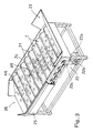
- the third embodiment of the invention is an example in which the fiber removing means have a plurality of rolls 21 which are provided at surfaces thereof with the treating surfaces T and which are disposed substantially close to each other.
- a rotation driving mechanism 22 is provided for rotating the rolls 21 in a same direction as shown in FIG. 3.
- This embodiment is similar to the conventional apparatus shown in FIG. 12, but the hair-implanted rolls are replaced by the rolls of the present invention.
- the sprinkling treatment from above can be employed in this embodiment according to characteristics and shapes of the food.
- the plurality of rolls 21 provided at the surfaces thereof with the treating surfaces T formed of a hook-and-loop fasteners are arranged substantially horizontally and substantially without a distance from each other.
- the rolls 21 are supported by a frame 24 and can be rotated in the same direction shown by arrows A6.
- a mechanism can be employed for transmitting a rotational force of a sprocket 22b of a motor 22a with a speed-reducing mechanism to sprockets mounted to the respective rolls 21 through a chain 22c or the like.
- the food 1 supplied from a supply portion 23 rolls down and is carried to the downstream side in a direction shown by an arrow A5 by the rotation of the rolls 21 while coming into contact with the treating surfaces T on the surfaces of the rolls 21 and is discharged through the discharge portion 26.
- the hair-implanted rolls of the conventional apparatus shown in FIG. 13 may be replaced by the rolls according to the present invention. In this case, separation of the fibrous contaminants from the food is favorable and the removing efficiency is further improved.
- the fourth embodiment according to the invention is an example in which the fiber removing means have a pipe-shaped body 30 provided at the inner face thereof with the treating surface T and rotatably supported in a state in which the pipe-shaped body 30 is inclined with respect to the horizontal plane, and have a rotation driving mechanism 31 for rotating the pipe-shaped body 30 as shown in FIGS. 4A and 4B.
- the pipe-shaped body 30 is a cylinder having a circular shape in cross-section as shown in FIG. 4B.
- a hopper-shaped supply portion 32 is provided to an end portion on the upper side of the inclination of the pipe-shaped body 30, and the end portion of the supply portion 32 is inserted into the cylinder.
- Racks 31a are mounted on two positions of the outer periphery of a body portion of the pipe-shaped body 30 and are supported for rotation by four pinions 31b and bearings 31c thereof mounted to a frame.
- the rotation driving mechanism 31 comprises a single driving device or a plurality of driving devices (not shown) in addition to the racks 31a, pinions 31b, and bearings 31c.
- the food 1 introduced from the supply portion 32 drops while being raked up as shown by an arrow A8 by the rotation of the pipe-shaped body 30 in the direction shown by an arrow A7.
- the food 1 is agitated vigorously and carried to the downstream side while coming into contact with the hook-and-loop fasteners intimately and repeatedly.
- fibrous contaminants or the like are separated from the food 1 and come into contact with and are caught by the hooks of hook-and-loop fasteners.
- the pipe-shaped body 30 having the circular shape in cross-section as shown in FIG. 4B is used, such a pipe-shaped body 30 can be applied to a wide range of food from small food to relatively big food, because the treating surface T is smooth.
- the pipe-shaped body 30 not only the pipe-shaped body 30 having the circular shape in cross-section, but also the pipe-shaped bodies 30 shown in FIGS. 5A to 5D can be employed.
- the pipe-shaped bodies 30 shown in FIGS. 5A to 5D have the following advantages with respect to food to be treated.
- FIG. 5A shows a pipe-shaped body 30 comprising partial elements which are formed by attaching hook-and-loop fasteners to rectangular plates and are arranged to form a polygon.
- FIG. 5B shows a pipe-shaped body 30 comprising elements which are formed by attaching hook-and-loop fasteners to faces of small-diameter cylinders and are arranged without a distance therebetween to form a cylinder. It is possible to clean the contaminants adhering to the elements easily by rotating the individual small cylinders through 180° in a state in which the elements are arranged.
- the apparatus has a further improved raking-up performance as compared with the above apparatus having the flat plates, because the contact between the food or the like and the hook-and-loop fasteners is intimate, and the contaminants can be removed favorably.
- FIG. 5C shows an example in which the cylindrical elements shown in FIG. 5B are replaced by polygonal elements.
- FIG. 5D shows a structure comprising a plurality of raking-up blades which can easily be attached and detached and which are attached at their raking-up faces with hook-and-loop fasteners.
- agitation by raking up is made vigorously and attachment, detachment, and cleaning of the contaminant removing elements are facilitated.
- the fifth embodiment of the present invention is an example in which the food mixture can be liquid including food 1
- the fiber removing means have a flow tank 41 for causing a liquid 43 to flow, and flow controlling plates 42 for causing the liquid 43 to flow in a non-linear manner in the flow tank 41, wherein the flow controlling plates 42 are provided with the treating surfaces T as shown in FIG. 6.
- a circulation piping having a pump As a mechanism for causing the liquid 43 to flow through the flow tank 41, it is possible to use a circulation piping having a pump, to use liquid supplied from the upstream side in one pass, or to use flow of a washing step of a conventional apparatus (not shown).
- a liquid which is a food mixture a mixture of food and liquid such as water and salt water, or food which itself contains food in liquid can be used.
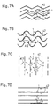
- FIGS. 7A to 7C Examples of the flow controlling plates 42 are shown in FIGS. 7A to 7C.
- the flow controlling plates 42 are provided with treating surfaces T formed of the hook-and-loop fasteners.
- the treating surface T may be provided to the entire flow controlling plate 42 or only to portions of the flow controlling plate 42 which the food 1 in liquid hits.
- flat flow controlling plates 42 as shown in FIG. 7D are slightly more effective than a conventional apparatus. A contact between such flat flow controlling plates 42 and the food and separation of the fibrous contaminants from the food 1 is favorable in some cases depending on flow conditions or the kind of food. A considerable effect can be exhibited in such cases.
- air spraying pipes 44 are provided below flow passages, and the food mixture is aerated from openings 44a of the air spraying pipes 44 to be agitated, thereby increasing the contaminant removing effect.
- the fibrous contaminants caught by the hook-shaped projections hardly flow into fluid again.
- a solid-liquid separating device 45 such as a screen conveyer is provided on the downstream side of the flow controlling plates 42.
- a porous bottom plate 46 for forming flow passages of the food 1 together with the flow controlling plates 42 below the flow controlling plates 42.
- the flow controlling plates 42 can stand on and can be supported by the porous bottom plate 46.
- punching metal or wire netting which allows efficient aeration from the air spraying tubes 44 is preferable.
- the fiber removing means mainly comprise a flow tank 110 for causing the liquid to flow, agitating plates 120 for causing the liquid to flow non-linearly in the flow tank 110, and a driving mechanism 130 for driving the agitating plates as shown in FIG. 8.
- the agitating plates 120 reciprocate and swing while aerating the liquid from the lower portion of the agitating plates 120 takes place.
- the flow tank 110 is partitioned into upper and lower portions by a partitioning plate 111 having the tendency to prevent the food from passing therethrough, and the food is caused to flow on the upper side of the partitioning plate 111 by causing the liquid to flow.
- the liquid flows by supplying running water from a feedwater box 112 disposed on the most upstream side of the flow tank 110 and discharging the water through a drain pipe (not shown) on the downstream side.
- the downstream-side face of the feedwater box 112 is defined with a plurality of slits such that the food flows uniformly and running water or the like supplied from a supply pipe 112a is released uniformly through the slits.
- the upper face of the feedwater box 112 is inclined such that the downstream side of the feedwater box 112 is lower for preventing the food from staying on the feedwater box 112.
- the food or the food mixture previously mixed with the liquid is supplied from a food supply portion 113 into the liquid and flows downstream on the upper side of the partitioning plate 111 by the above-described flow.
- the partitioning plate 111 punching metal or wire netting, which allows efficient aeration from below, is preferable.
- the agitating plates 120 have swinging axial centers which are substantially in parallel to the flow direction of the flow tank 110 and are caused to reciprocate and swing from their reference positions where the agitating plates 120 are substantially vertical to a liquid level by the driving mechanism 130.
- the driving mechanism 130 mainly comprises a substantially angular U-shaped fixed frame 131 bridging long side frames of the upper end of the flow tank 110, swinging support portions 132 mounted at opposite lower ends of the fixed frame 131 and each having a swinging axis on the outer side of the swinging support portion 132.
- Swinging frames 133 are provided with lower ends thereof supported by the respective swinging support portions 132 for swinging movements; upper and lower links 134 and 135 are bridging both the swinging frames 133 through swinging axes; and an electric motor 136 is fixed to the fixed frame 131 for swinging the swinging frames 133 through a crank portion 133a by the rotation of a driving shaft as shown in FIG. 9.
- a portion of the fixed frame 131 to be attached with the electric motor 136 is defined with an elongated hole 131a such that the fixing position of the electric motor 136 can be adjusted in the vertical direction, thereby adjusting the range of angle of the swinging movement.
- the crank portion 133a changes the rotary movement into a reciprocating movement by a sliding movement of a crank pin on the driving shaft side of the electric motor 136 in an inside groove of a channel member joined to the swinging frame 133.
- Another fixed frame 131 is provided on the downstream side to form a pair with the fixed frame 131 on the upstream side, and two bridging frames 131a bridge the fixed frames 131 as shown in FIG. 8.
- Two swinging movement-transmitting rods 134a bridge the upper links 134 on the upstream side and the downstream side so as to transmit swinging movements on the upstream side to the downstream side.
- the agitating plates 120 are axially supported at two positions on the upper link 134 and the lower link 135 to be vertical to a water surface at a reference position where the swinging frames 133 are vertical.
- the agitating plates 120 are caused to swing through the upper and lower links 134 and 135 while being kept in parallel to the swinging frames 133.
- swinging axial centers of the agitating plates 120 are positioned on the agitating plates 120, or on extended faces thereof, at the same height as the swinging axial centers of the swinging frames 133.
- Each of the agitating plates 120 mainly comprises swinging links 121 each of which is axially supported at two positions of the upper link 134 and the lower link 135, a long plate 122 joined to lower end portions of the two swinging links 121, and a hook-and-loop fastener 123 which covers the long plate 122 and is fixed to the long plate 122 by utilizing a plurality of holes 122a in the long plate 122 as shown in a perspective view and a sectional view of FIGS. 10A and 10B.
- the hook-and-loop fastener 123 comprises hook parts of the hook-and-loop fastener with cut loops folded in two such that the surface of the hook-and-loop fastener 123 is on the outside. At positions of the hook-and-loop fastener 123, which correspond to the holes 122a in the long plate 122, male and female hooks 123a are provided.
- the hook-and-loop fastener 123 is fixed to the long plate 122.
- the hook-and-loop fastener 123 may be in a bag shape with its upper portion open. In this case, after folding the hook-and-loop fastener 123 in two, the lower portions of opposite side end portions may be sewn. Such a hook-and-loop fastener in the bag shape is effective when the agitating plates are cantilevered.
- aeration means 115 having releasing outlets 118a for releasing gas into the liquid are provided.
- the aeration means 115 mainly comprise an air supply portion 116 for supplying gas such as air, a supply pipe 117 extending from the air supply portion 116 and communicating with a portion inside the flow tank 110 and below the partitioning plate 111, and branch pipes 118 which branch off from the supply pipe 117 to extend below the respective agitating plates 120.
- a plurality of releasing pipes having the releasing outlets 118a are provided to upper sides of the branch pipes 118.
- a communicating pipe 118b is provided to the downstream end portions of the branch pipes 118, and pressure loss of the releasing outlets 118a is increased to maintain a high pressure in the pipes.
- the releasing outlets 118a are formed at a proper distance, for example of 5 to 50 cm from each other, such that a vertical agitation can be carried out favorably by an upward-moving stream and a downward-moving stream.
- a solid-liquid separating device 114 such as a screen conveyer is provided on the most downstream side of the flow tank 110.
- the flow tank 110 is supported by a box-shaped frame and can be moved by using casters. At the bottom portion of the flow tank 110, a discharge portion 119 is provided.
- the process for food treatment according to the invention is a process for removing fibrous contaminants included in the food or the food mixture and comprises the step of bringing the treating surface on which a plurality of hooks are formed to stand, into contact with the food or the food mixture. Such a step is carried out by using the apparatus according to the embodiments as described above. At this time, it is preferable that the hooks are made of flexible material and that the treating surface is formed of the hook parts of the hook-and-loop fasteners with cut loops.
- the apparatus according to FIG. 6 was used.
- the hook parts of the hook-and-loop fasteners, produced by KURARAY Co., Ltd., with cut loops were attached as treating surfaces to the entire faces of the treating surfaces.
- Chopped cucumbers, an imported product cut in round slices with a thickness of 4 mm, made in China were treated by every 3 tons, 35 times in total, and at a linear velocity of water flow of about 10 cm/s.
- the number of fibrous contaminants for example threads, hairs, pieces of resin, and the like, which had adhered to the hook-and-loop fasteners was counted. Results are shown in Table 1. 111 27 35 72 41 56 34 29 56 92 87 32 96 20 87 28 14 91 70 35 61 36 16 24 26 16 24 46 38 51 41 49 35 27 33
- the removing rate was 50 % or less, when the same food was treated by using the conventional apparatus as shown in FIG. 12.
- Example 2 A treatment similar to the Example 1 was carried out in which the food is replaced by 100 kg of seeds of a beefsteak plant made in Japan. As a result, 19 seeds of dandelion and 41 hair-shaped microscopic contaminants could be removed. Furthermore, few seeds of the beefsteak plant were caught on the treating surfaces, and it was found that the apparatus was also effective to microscopic foods.
Landscapes
- Life Sciences & Earth Sciences (AREA)
- Chemical & Material Sciences (AREA)
- Engineering & Computer Science (AREA)
- Food Science & Technology (AREA)
- Polymers & Plastics (AREA)
- Preparation Of Fruits And Vegetables (AREA)
- General Preparation And Processing Of Foods (AREA)
- Apparatuses For Bulk Treatment Of Fruits And Vegetables And Apparatuses For Preparing Feeds (AREA)
Applications Claiming Priority (4)
| Application Number | Priority Date | Filing Date | Title |
|---|---|---|---|
| JP19133298 | 1998-07-07 | ||
| JP10-191332A JP2867258B1 (ja) | 1998-07-07 | 食品処理装置 | |
| JP5638599 | 1999-03-04 | ||
| JP11056385A JP2000245423A (ja) | 1999-03-04 | 1999-03-04 | 食品洗浄装置 |
Publications (2)
| Publication Number | Publication Date |
|---|---|
| EP0970622A2 true EP0970622A2 (de) | 2000-01-12 |
| EP0970622A3 EP0970622A3 (de) | 2001-01-31 |
Family
ID=26397339
Family Applications (1)
| Application Number | Title | Priority Date | Filing Date |
|---|---|---|---|
| EP99113166A Withdrawn EP0970622A3 (de) | 1998-07-07 | 1999-07-07 | Vorrichtung und Verfahren zur Lebensmittelbehandlung |
Country Status (4)
| Country | Link |
|---|---|
| EP (1) | EP0970622A3 (de) |
| KR (1) | KR20000016907A (de) |
| CN (1) | CN1106232C (de) |
| TW (1) | TW403635B (de) |
Cited By (1)
| Publication number | Priority date | Publication date | Assignee | Title |
|---|---|---|---|---|
| CN118592637A (zh) * | 2024-06-28 | 2024-09-06 | 临沂中利食品有限公司 | 一种大蒜深加工烘干设备 |
Families Citing this family (6)
| Publication number | Priority date | Publication date | Assignee | Title |
|---|---|---|---|---|
| CN101982377A (zh) * | 2010-10-14 | 2011-03-02 | 张国利 | 农产品清洗分拣装包机 |
| CN103478858B (zh) * | 2012-06-11 | 2017-11-14 | 程伟 | 一种水果蔬菜清洗保鲜方法 |
| CN107028205A (zh) * | 2017-05-05 | 2017-08-11 | 榆林学院 | 一种果蔬清洗装置及方法 |
| CN107951671B (zh) * | 2017-11-09 | 2020-03-17 | 张铁峰 | 一种多功能改善人体微循环的理疗装置 |
| CN112337841A (zh) * | 2020-08-15 | 2021-02-09 | 苏州云刚智能科技有限公司 | 一种食品清洗方法 |
| CN113057346B (zh) * | 2021-03-11 | 2022-04-05 | 唐山市盛川农产品股份有限公司 | 一种绿色蔬菜净菜加工装置 |
Family Cites Families (7)
| Publication number | Priority date | Publication date | Assignee | Title |
|---|---|---|---|---|
| US2548826A (en) * | 1946-02-26 | 1951-04-10 | American Machinery Corp | Demountable brushing machine |
| DK130235B (da) * | 1972-09-25 | 1975-01-27 | Nykobing Sukker | Apparat til optagning af tavede eller langfibrede bestanddele fra en væskegennemstrømmet rende. |
| GB2029202A (en) * | 1978-09-02 | 1980-03-19 | Howells P | Cleaning appliance |
| DE3301766A1 (de) * | 1983-01-20 | 1984-07-26 | Günter 2730 Zeven Gerlach | Vorrichtung (krautfaenger) zum aussondern von faserigen gegenstaenden aus einem zuckerrueben aufweisenden gemisch |
| US4671976A (en) * | 1985-10-31 | 1987-06-09 | Vidal Stella M | Web-type stock material with upwardly projecting filamentary elements and defined periphery |
| US5307738A (en) * | 1993-06-25 | 1994-05-03 | Amstad John H | Food processing machine |
| JP2652943B2 (ja) * | 1995-02-03 | 1997-09-10 | 芳雄 藤田 | 大根の水洗い兼ひげ根除去装置 |
-
1999
- 1999-06-28 TW TW088110884A patent/TW403635B/zh not_active IP Right Cessation
- 1999-07-07 KR KR1019990027207A patent/KR20000016907A/ko not_active Withdrawn
- 1999-07-07 CN CN99109539A patent/CN1106232C/zh not_active Expired - Fee Related
- 1999-07-07 EP EP99113166A patent/EP0970622A3/de not_active Withdrawn
Non-Patent Citations (1)
| Title |
|---|
| None |
Cited By (1)
| Publication number | Priority date | Publication date | Assignee | Title |
|---|---|---|---|---|
| CN118592637A (zh) * | 2024-06-28 | 2024-09-06 | 临沂中利食品有限公司 | 一种大蒜深加工烘干设备 |
Also Published As
| Publication number | Publication date |
|---|---|
| TW403635B (en) | 2000-09-01 |
| CN1249215A (zh) | 2000-04-05 |
| CN1106232C (zh) | 2003-04-23 |
| EP0970622A3 (de) | 2001-01-31 |
| KR20000016907A (ko) | 2000-03-25 |
Similar Documents
| Publication | Publication Date | Title |
|---|---|---|
| KR101928542B1 (ko) | 홍합의 세척, 분리 및 선별장치 | |
| KR100927000B1 (ko) | 초음파를 이용한 세척장치 | |
| US5894936A (en) | Drum separator for brine shrimp eggs | |
| EP0970622A2 (de) | Vorrichtung und Verfahren zur Lebensmittelbehandlung | |
| DE69224339T2 (de) | Flexible und kompakte Maschine zum Reinigen von Probenflaschen | |
| DE4415976A1 (de) | Nahrungsmittelverarbeitungsmaschine | |
| CA2307875C (en) | Shrimp peeling apparatus | |
| JP3401001B2 (ja) | 芝の処理 | |
| US6470898B1 (en) | Paper stock cleaning apparatus | |
| CN109043603A (zh) | 鲜红枣加工生产装置 | |
| DE7511465U (de) | Vorrichtung zum waschen und/oder trocknen o.dgl. von gegenstaenden | |
| US6530203B2 (en) | Sprouting beans refinement apparatus | |
| US5862821A (en) | Apparatus for washing leafy plant products | |
| JP4711047B2 (ja) | 野菜等の洗浄装置 | |
| JPH11164678A (ja) | 浸漬大豆の子葉、胚軸、種皮分離装置 | |
| US2503556A (en) | Vegetable washer | |
| JP2000245423A (ja) | 食品洗浄装置 | |
| JP2867258B1 (ja) | 食品処理装置 | |
| US20090008300A1 (en) | Bean sprouts-like articles refining method and refining device | |
| JP2000237690A (ja) | 食品処理装置 | |
| US4288314A (en) | Apparatus for separating adhering dried fruits and the like | |
| JP2001321068A (ja) | 食品洗浄装置 | |
| JPH11196835A (ja) | 食品の洗浄装置 | |
| JPH0319726Y2 (de) | ||
| JP3342383B2 (ja) | 混在異物の除去方法及び除去装置 |
Legal Events
| Date | Code | Title | Description |
|---|---|---|---|
| PUAI | Public reference made under article 153(3) epc to a published international application that has entered the european phase |
Free format text: ORIGINAL CODE: 0009012 |
|
| AK | Designated contracting states |
Kind code of ref document: A2 Designated state(s): DE GB |
|
| AX | Request for extension of the european patent |
Free format text: AL;LT;LV;MK;RO;SI |
|
| PUAL | Search report despatched |
Free format text: ORIGINAL CODE: 0009013 |
|
| AK | Designated contracting states |
Kind code of ref document: A3 Designated state(s): AT BE CH CY DE DK ES FI FR GB GR IE IT LI LU MC NL PT SE |
|
| AX | Request for extension of the european patent |
Free format text: AL;LT;LV;MK;RO;SI |
|
| 17P | Request for examination filed |
Effective date: 20010517 |
|
| AKX | Designation fees paid |
Free format text: DE GB |
|
| STAA | Information on the status of an ep patent application or granted ep patent |
Free format text: STATUS: THE APPLICATION HAS BEEN WITHDRAWN |
|
| 18W | Application withdrawn |
Effective date: 20040510 |