EP0970778B1 - Broche de moteur échangeable pour machine outil - Google Patents
Broche de moteur échangeable pour machine outil Download PDFInfo
- Publication number
- EP0970778B1 EP0970778B1 EP99112518A EP99112518A EP0970778B1 EP 0970778 B1 EP0970778 B1 EP 0970778B1 EP 99112518 A EP99112518 A EP 99112518A EP 99112518 A EP99112518 A EP 99112518A EP 0970778 B1 EP0970778 B1 EP 0970778B1
- Authority
- EP
- European Patent Office
- Prior art keywords
- spindle
- tool
- motor
- actuating piston
- motor spindle
- Prior art date
- Legal status (The legal status is an assumption and is not a legal conclusion. Google has not performed a legal analysis and makes no representation as to the accuracy of the status listed.)
- Expired - Lifetime
Links
- 238000003754 machining Methods 0.000 abstract description 5
- 230000004308 accommodation Effects 0.000 description 1
- 230000008878 coupling Effects 0.000 description 1
- 238000010168 coupling process Methods 0.000 description 1
- 238000005859 coupling reaction Methods 0.000 description 1
- 230000001771 impaired effect Effects 0.000 description 1
- 238000003780 insertion Methods 0.000 description 1
- 230000037431 insertion Effects 0.000 description 1
- 238000003801 milling Methods 0.000 description 1
- 239000002245 particle Substances 0.000 description 1
- 238000004804 winding Methods 0.000 description 1
Images
Classifications
-
- B—PERFORMING OPERATIONS; TRANSPORTING
- B23—MACHINE TOOLS; METAL-WORKING NOT OTHERWISE PROVIDED FOR
- B23B—TURNING; BORING
- B23B31/00—Chucks; Expansion mandrels; Adaptations thereof for remote control
- B23B31/02—Chucks
- B23B31/24—Chucks characterised by features relating primarily to remote control of the gripping means
- B23B31/26—Chucks characterised by features relating primarily to remote control of the gripping means using mechanical transmission through the working-spindle
- B23B31/261—Chucks characterised by features relating primarily to remote control of the gripping means using mechanical transmission through the working-spindle clamping the end of the toolholder shank
Definitions
- the invention relates to an interchangeable motor spindle for a machine tool with a trunnion, which in a Recording the machine tool is attachable, and one the trunnion attached housing that an electric motor and a spindle that can be driven by this with a Tool holder for a tool for machining workpiece machining contains (see WO 96/39274).
- Motor spindles are used in cutting machine tools Perform certain machining operations. she have an electric motor rotating at a very high speed compact design with a motor shaft serving as a spindle, which is the editing tool, for example one Milling head, carries.
- a motor shaft serving as a spindle
- the editing tool for example one Milling head
- carries From WO 96/39274 is an interchangeable Motor spindle of the specified type known, in which on the A spindle is attached to the housing of the motor spindle e.g. in the tool holder of the main spindle of a machine tool can be used.
- the tool is here a tool coupling with the spindle of the motor spindle connected and can only by hand, for example Purpose of renewal to be resolved from this.
- the invention has for its object a replaceable To create a motor spindle of the type mentioned at the beginning, where the tool on the motor spindle automatically can be changed.
- a motor spindle of the type mentioned in that the Spindle is designed as a hollow shaft and in its longitudinal bore one by spring force in a closed position held quick release device for tightening a Tool or a tool holder and that the housing coaxially to the spindle with a cylinder arranged by a pressure medium movable actuating piston through which the clamping device by means of a the longitudinal bore of the spindle axially displaceable plunger is movable into a release position.
- a motor spindle is created which in CNC-controlled machine tools automatically instead a slow running tool in the tool holder the main spindle can be used for certain Use machining operations with high-speed drivable tools to be able to. These are driven by the motor spindle Tools can also automatically according to the invention be changed without changing the Motor spindle is required. It is therefore for the drive high-speed tools only a single motor spindle required so that no purchase cost further motor spindles are created. Another advantage can be seen in the fact that for the accommodation of the tools, which are driven by the motor spindle, only one small tool magazine is required because when changing tools the tools alone and not together with each a motor spindle in the magazine.
- the axis of rotation of the spindle coincides with the axis of rotation of the Main spindle together, so is preferably the cylinder arranged between the trunnion and the housing.
- the cylinder consists of detachable with the housing and parts connected to the trunnion, which by means of Centering surfaces to each other, to the housing and to the trunnion are centered. This makes a form-fitting and very Precisely producible center alignment of trunnions and Motor spindle reached so that when inserting the motor spindle the center position of the tool in the main spindle the motor spindle is defined and not re-measured must become.
- the cylinder can advantageously be made of a pot-shaped, with the housing connectable bottom part and with the support pin connectable cover part, which centered to each other by means of centering surfaces and by axially parallel screws are connected.
- the Actuating piston has a central through hole that communicates with the longitudinal bore of the spindle and in a throttle orifice is provided and that in the longitudinal bore the spindle in the tool holder of the spindle opening free flow path is formed. hereby can when compressed air is applied to the actuating piston one defined by the throttle orifice, the actuation pressure amount of air not impaired by the Through hole and the longitudinal hole in the receiving cone the tool holder to get when inserting a new tool possibly adhering to the tool cone Remove dirt particles from the clamping surfaces.
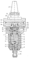
- the drawing shows an axial section through a motor spindle 1, which consists of a multi-part housing 2, a stator winding 3 and one supported by means of roller bearings 4 Spindle 5 with a rotor 6 is made.
- the spindle 5 is with a continuous longitudinal bore 7 provided on the in the drawing lower end in a tapered bore 8 for receiving a tool cone 9 opens.
- the tool cone 9 can either be directly on a processing tool or, as shown in the drawing, on a tool holder 10 be attached.
- a quick release device 11 In the longitudinal bore 7 is axial slidably a quick release device 11 and a this firmly connected plunger 12 mounted axially.
- the quick release device 11 acts with a clamping pin 13 together, which is attached to the tool cone 9 is.
- the clamping pin 13 from the quick release device 11 positively gripped and by the force of prestressed Disc springs 14 are drawn into the spindle 5, whereby the tool taper 9 is clamped in the taper bore 8 becomes.
- the plate springs 14 are arranged on the tappet 12 and are supported in the axial direction on the head 15 of the Ram 12 on the one hand and on a stop ring 16 on the other from a shoulder in the longitudinal bore 7 is applied.
- a cylinder 17 is flanged to the upper end of the housing 2, that of a pot-shaped base part 18 and one Cover part 19 is made.
- the bottom part 18 is by means of Drawing of screws, not shown, on the housing 2 attached and has a projection 20 with a centering surface that engages in a central housing bore without play.
- the cover part 19 is with a central, cylindrical Provided recess 21 in which a cylindrical Flange 22 of a trunnion 23 fastened by means of screws is.
- the cylinder 17 encloses a cylinder chamber 24, in which is an actuating piston 25.
- a cylindrical one Piston extension 26 of the actuating piston 25 extends through a hole in the bottom part 18 and ends in the illustrated rest position of the actuating piston 25 at a short distance from the head 15 of the plunger 12.
- the actuating piston 25 is actuated by a return spring 27 held in the rest position shown.
Landscapes
- Engineering & Computer Science (AREA)
- Mechanical Engineering (AREA)
- Gripping On Spindles (AREA)
- Turning (AREA)
- Jigs For Machine Tools (AREA)
- Automatic Tool Replacement In Machine Tools (AREA)
- Epoxy Resins (AREA)
Claims (6)
- Broche de moteur échangeable pour machine-outil avec un tourillon d'appui pouvant être fixé dans un logement de la machine-outil et avec un boítier fixé au tourillon d'appui et contenant un moteur électrique ainsi qu'une broche pouvant être entraínée en rotation par ce moteur et qui est munie d'un logement pour outil pour un outil pour usinage par enlèvement de copeaux, caractérisé en ce que la broche (5) a la forme d'un arbre creux présentant dans son trou longitudinal (7) un dispositif de bridage rapide (11) maintenu en position verrouillée par une force de ressort pour serrer un outil ou un porte-outil (10), et en ce qu'est placé sur le boítier (2) de façon coaxiale à la broche (5) un cylindre (17) avec un piston de commande (25) pouvant être déplacé au moyen d'un fluide de pression et grâce auquel le dispositif de bridage (11) peut être déplacé en position de déverrouillage au moyen d'un coulisseau (12) pouvant coulisser de façon axiale dans le trou longitudinal (7) de la broche (5).
- Broche de moteur selon la revendication 1, caractérisé en ce que le cylindre (17) est placé entre le tourillon d'appui (23) et le boítier (2).
- Broche de moteur selon la revendication 2, caractérisé en ce que le cylindre (17) est constitué de pièces (18, 19) amovibles reliées au boítier (2) et au tourillon d'appui (23), ces pièces étant centrées l'une par rapport à l'autre, par rapport au boítier (2) et par rapport au tourillon d'appui (23) à l'aide de surfaces de centrage.
- Broche de moteur selon l'une des revendications précédentes, caractérisé en ce que le cylindre (17) est constitué d'un fond (18) en forme de pot pouvant être relié au boítier et d'un couvercle (19) pouvant être relié au tourillon d'appui (23), ce fond et ce couvercle étant centrés l'un par rapport à l'autre au moyen de surfaces de centrage et reliés ensemble par des vis parallèles à l'axe.
- Broche de moteur selon d'une des revendications précédentes, caractérisé en ce que, lorsque le piston de commande (25) est en position de repos, il y a un espace libre entre le piston de commande (25), la broche (5) et le coulisseau (12) et en ce que des moyens (27) sont prévus pour ramener le piston de commande (25) en position de repos après actionnement.
- Broche de moteur selon l'une des revendications précédentes, caractérisé en ce que le piston de commande (25) présente un trou de passage central qui est relié au trou longitudinal (7) de la broche (5) et dans lequel est prévu un orifice de jaugeage et en ce qu'une voie d'écoulement aboutissant dans le logement pour outil de la broche (5) est formée dans le trou longitudinal (7) de la broche (5).
Applications Claiming Priority (2)
| Application Number | Priority Date | Filing Date | Title |
|---|---|---|---|
| DE29812170U | 1998-07-07 | ||
| DE29812170U DE29812170U1 (de) | 1998-07-07 | 1998-07-07 | Auswechselbare Motorspindel für eine Werkzeugmaschine |
Publications (3)
| Publication Number | Publication Date |
|---|---|
| EP0970778A1 EP0970778A1 (fr) | 2000-01-12 |
| EP0970778B1 true EP0970778B1 (fr) | 2002-01-02 |
| EP0970778B2 EP0970778B2 (fr) | 2004-09-15 |
Family
ID=8059597
Family Applications (1)
| Application Number | Title | Priority Date | Filing Date |
|---|---|---|---|
| EP99112518A Expired - Lifetime EP0970778B2 (fr) | 1998-07-07 | 1999-07-01 | Broche de moteur échangeable pour machine outil |
Country Status (6)
| Country | Link |
|---|---|
| EP (1) | EP0970778B2 (fr) |
| AT (1) | ATE211421T1 (fr) |
| DE (2) | DE29812170U1 (fr) |
| DK (1) | DK0970778T4 (fr) |
| ES (1) | ES2144387T5 (fr) |
| PT (1) | PT970778E (fr) |
Cited By (1)
| Publication number | Priority date | Publication date | Assignee | Title |
|---|---|---|---|---|
| CN106799502A (zh) * | 2017-03-25 | 2017-06-06 | 兰溪瑞鼎机床股份有限公司 | 伺服车削动力头 |
Families Citing this family (5)
| Publication number | Priority date | Publication date | Assignee | Title |
|---|---|---|---|---|
| DE19916710B4 (de) * | 1999-04-14 | 2005-08-04 | Lang, Günter | Werkzeugantriebseinrichtung, insbesondere für Werkzeugmaschinen |
| DE19928839B4 (de) * | 1999-06-24 | 2005-02-17 | Actech Gmbh Advanced Casting Technologies Giessereitechnologie | Spindeladapter für eine stationäre Werkzeugmaschine |
| DE29914930U1 (de) * | 1999-08-26 | 1999-12-09 | Deckel Maho GmbH, 87459 Pfronten | Bearbeitungseinheit einer Werkzeugmaschine |
| DE10143388A1 (de) * | 2001-09-04 | 2003-03-27 | Komet Stahlhalter Werkzeuge | Werkzeugmaschine mit Doppelspindel sowie Vorsatzkopf für derartige Werkzeugmaschinen |
| WO2012055120A1 (fr) * | 2010-10-29 | 2012-05-03 | 大连科德数控有限公司 | Support d'outil entraîné directement par un moteur électrique pour centre d'usinage à tournage-fraisage combiné |
Family Cites Families (8)
| Publication number | Priority date | Publication date | Assignee | Title |
|---|---|---|---|---|
| DE3714562A1 (de) † | 1987-04-30 | 1988-11-10 | Deckel Ag Friedrich | Werkzeugspindelanordnung mit einem elektrischen antriebsmotor |
| JP2821012B2 (ja) * | 1990-08-07 | 1998-11-05 | 東芝機械株式会社 | 自動工具交換可能な増速ヘッド |
| DE9100557U1 (de) † | 1991-01-18 | 1991-04-11 | Hermann Kolb Maschinenfabrik AG, 5000 Köln | Handhabungsgerät für Bearbeitungszentren der spanabhebenden Fertigung |
| DE4239769C2 (de) * | 1992-11-26 | 1994-09-01 | Doerries Scharmann Gmbh | Vorrichtung zum Befestigen von Werkzeugen an einer Werkzeugmaschinenspindel oder einem Werkzeughalter |
| DE19618610A1 (de) | 1995-05-13 | 1996-11-14 | Gerhard Dr Ing Huber | Werkzeugspindel mit Spanneinrichtung |
| US5697739A (en) * | 1995-06-06 | 1997-12-16 | Kennametal Inc. | Angle spindle attachment |
| DE29520427U1 (de) | 1995-12-22 | 1996-02-08 | Deckel Maho Gmbh | Spindeleinheit für Werkzeugmaschinen |
| DE19615382A1 (de) | 1996-04-18 | 1997-10-23 | Kurt Dipl Ing Kessler | Motor einer Maschine (Werkzeugmaschine) mit einer Kühlung mittels Heatpipe und einer mechanischpneumatischen Spannvorrichtung |
-
1998
- 1998-07-07 DE DE29812170U patent/DE29812170U1/de not_active Expired - Lifetime
-
1999
- 1999-07-01 AT AT99112518T patent/ATE211421T1/de not_active IP Right Cessation
- 1999-07-01 DK DK99112518T patent/DK0970778T4/da active
- 1999-07-01 EP EP99112518A patent/EP0970778B2/fr not_active Expired - Lifetime
- 1999-07-01 DE DE59900702T patent/DE59900702D1/de not_active Expired - Fee Related
- 1999-07-01 PT PT99112518T patent/PT970778E/pt unknown
- 1999-07-01 ES ES99112518T patent/ES2144387T5/es not_active Expired - Lifetime
Cited By (1)
| Publication number | Priority date | Publication date | Assignee | Title |
|---|---|---|---|---|
| CN106799502A (zh) * | 2017-03-25 | 2017-06-06 | 兰溪瑞鼎机床股份有限公司 | 伺服车削动力头 |
Also Published As
| Publication number | Publication date |
|---|---|
| DE59900702D1 (de) | 2002-02-28 |
| DE29812170U1 (de) | 1998-09-10 |
| EP0970778B2 (fr) | 2004-09-15 |
| DK0970778T3 (da) | 2002-04-15 |
| ES2144387T5 (es) | 2005-04-01 |
| ES2144387T1 (es) | 2000-06-16 |
| EP0970778A1 (fr) | 2000-01-12 |
| DK0970778T4 (da) | 2004-11-01 |
| ES2144387T3 (es) | 2002-07-01 |
| ATE211421T1 (de) | 2002-01-15 |
| PT970778E (pt) | 2002-06-28 |
Similar Documents
| Publication | Publication Date | Title |
|---|---|---|
| DE3324312C2 (de) | Werkzeugmaschine mit Werkzeugwechselvorrichtung | |
| WO1996027468A1 (fr) | Commande de positionnement, notamment sur machines-outils, et tete porte-outil utilisee avec une telle commande | |
| CH698920B1 (de) | Werkstückspindelstock. | |
| WO2006042700A1 (fr) | Dispositif de serrage | |
| EP0970778B2 (fr) | Broche de moteur échangeable pour machine outil | |
| DE69308053T2 (de) | Vorrichtung für die Hauptspindel einer Werkzeugmaschine | |
| EP2844413B1 (fr) | Mandrin | |
| EP0297468B1 (fr) | Dispositif de fixation d'une lame de scie | |
| EP0185889A2 (fr) | Dispositif de serrage d'outil en particulier pour fraiseuses et aléseuses | |
| DE3822565C2 (fr) | ||
| EP3500769B2 (fr) | Procédé d'usinage intérieur d'un étrier de frein d'un frein à disque | |
| DE3634018C2 (fr) | ||
| DE69221804T2 (de) | Nutenschneidgerät | |
| WO2006092110A1 (fr) | Tourelle revolver pour outillage dotee d'un outil entraine en rotation sur sa face frontale | |
| DE3128228C2 (fr) | ||
| DE102008034858A1 (de) | Vorrichtung zum Honen von Wandungen von Bohrungen in Werkstücken auf Bearbeitungszentren | |
| DE19531104C2 (de) | Drehmaschinen-Spannfutter mit verstellbarer Exzentrizität | |
| DE102007038312A1 (de) | System zur Aufnahme von Bearbeitungsköpfen an einem Bearbeitungszentrum | |
| DE102012102469A1 (de) | Werkzeugmaschine mit Spindeleinheit | |
| EP1109649A1 (fr) | Machine-outil | |
| DE3918903C2 (fr) | ||
| DE732012C (de) | Mittels Pressluft angetriebene Bohrmaschine | |
| EP0172571B1 (fr) | Mandrin | |
| DE60019779T2 (de) | Pneumatisch betätigte vorrichtung zum zentrieren eines werkstückes in einer maschine | |
| DE3932574C1 (en) | Device for installation of open end- spinning rotors - comprises support with groove for holding replaceable centering prism, so that height of prism can be adapted to different bearing loads |
Legal Events
| Date | Code | Title | Description |
|---|---|---|---|
| PUAI | Public reference made under article 153(3) epc to a published international application that has entered the european phase |
Free format text: ORIGINAL CODE: 0009012 |
|
| AK | Designated contracting states |
Kind code of ref document: A1 Designated state(s): AT BE CH CY DE DK ES FI FR GB GR IE IT LI LU MC NL PT SE |
|
| AX | Request for extension of the european patent |
Free format text: AL;LT;LV;MK;RO;SI |
|
| 17P | Request for examination filed |
Effective date: 20000310 |
|
| EL | Fr: translation of claims filed | ||
| REG | Reference to a national code |
Ref country code: ES Ref legal event code: BA2A Ref document number: 2144387 Country of ref document: ES Kind code of ref document: T1 |
|
| GBC | Gb: translation of claims filed (gb section 78(7)/1977) | ||
| TCNL | Nl: translation of patent claims filed | ||
| AKX | Designation fees paid |
Free format text: AT BE CH CY DE DK ES FI FR GB GR IE IT LI LU MC NL PT SE |
|
| IECL | Ie: translation for ep claims filed | ||
| GRAG | Despatch of communication of intention to grant |
Free format text: ORIGINAL CODE: EPIDOS AGRA |
|
| GRAG | Despatch of communication of intention to grant |
Free format text: ORIGINAL CODE: EPIDOS AGRA |
|
| GRAH | Despatch of communication of intention to grant a patent |
Free format text: ORIGINAL CODE: EPIDOS IGRA |
|
| GRAH | Despatch of communication of intention to grant a patent |
Free format text: ORIGINAL CODE: EPIDOS IGRA |
|
| 17Q | First examination report despatched |
Effective date: 20011002 |
|
| GRAA | (expected) grant |
Free format text: ORIGINAL CODE: 0009210 |
|
| REG | Reference to a national code |
Ref country code: GB Ref legal event code: IF02 |
|
| AK | Designated contracting states |
Kind code of ref document: B1 Designated state(s): AT BE CH CY DE DK ES FI FR GB GR IE IT LI LU MC NL PT SE |
|
| PG25 | Lapsed in a contracting state [announced via postgrant information from national office to epo] |
Ref country code: GR Free format text: LAPSE BECAUSE OF FAILURE TO SUBMIT A TRANSLATION OF THE DESCRIPTION OR TO PAY THE FEE WITHIN THE PRESCRIBED TIME-LIMIT Effective date: 20020102 |
|
| REF | Corresponds to: |
Ref document number: 211421 Country of ref document: AT Date of ref document: 20020115 Kind code of ref document: T |
|
| REG | Reference to a national code |
Ref country code: CH Ref legal event code: EP |
|
| REG | Reference to a national code |
Ref country code: IE Ref legal event code: FG4D Free format text: GERMAN |
|
| REF | Corresponds to: |
Ref document number: 59900702 Country of ref document: DE Date of ref document: 20020228 |
|
| REG | Reference to a national code |
Ref country code: DK Ref legal event code: T3 |
|
| GBT | Gb: translation of ep patent filed (gb section 77(6)(a)/1977) |
Effective date: 20020409 |
|
| ET | Fr: translation filed | ||
| REG | Reference to a national code |
Ref country code: PT Ref legal event code: SC4A Free format text: AVAILABILITY OF NATIONAL TRANSLATION Effective date: 20020327 |
|
| REG | Reference to a national code |
Ref country code: ES Ref legal event code: FG2A Ref document number: 2144387 Country of ref document: ES Kind code of ref document: T3 |
|
| PG25 | Lapsed in a contracting state [announced via postgrant information from national office to epo] |
Ref country code: CY Free format text: LAPSE BECAUSE OF FAILURE TO SUBMIT A TRANSLATION OF THE DESCRIPTION OR TO PAY THE FEE WITHIN THE PRESCRIBED TIME-LIMIT Effective date: 20020731 |
|
| PLBE | No opposition filed within time limit |
Free format text: ORIGINAL CODE: 0009261 |
|
| 26N | No opposition filed | ||
| PLBQ | Unpublished change to opponent data |
Free format text: ORIGINAL CODE: EPIDOS OPPO |
|
| PLAA | Information modified related to event that no opposition was filed |
Free format text: ORIGINAL CODE: 0009299DELT |
|
| PLBI | Opposition filed |
Free format text: ORIGINAL CODE: 0009260 |
|
| PLBF | Reply of patent proprietor to notice(s) of opposition |
Free format text: ORIGINAL CODE: EPIDOS OBSO |
|
| 26 | Opposition filed |
Opponent name: DECKEL MAHO PFRONTEN GMBHPATENTANWAELTE Effective date: 20021002 |
|
| D26N | No opposition filed (deleted) | ||
| PLAX | Notice of opposition and request to file observation + time limit sent |
Free format text: ORIGINAL CODE: EPIDOSNOBS2 |
|
| PLBB | Reply of patent proprietor to notice(s) of opposition received |
Free format text: ORIGINAL CODE: EPIDOSNOBS3 |
|
| PUAH | Patent maintained in amended form |
Free format text: ORIGINAL CODE: 0009272 |
|
| STAA | Information on the status of an ep patent application or granted ep patent |
Free format text: STATUS: PATENT MAINTAINED AS AMENDED |
|
| 27A | Patent maintained in amended form |
Effective date: 20040915 |
|
| AK | Designated contracting states |
Kind code of ref document: B2 Designated state(s): AT BE CH CY DE DK ES FI FR GB GR IE IT LI LU MC NL PT SE |
|
| REG | Reference to a national code |
Ref country code: CH Ref legal event code: AEN Free format text: AUFRECHTERHALTUNG DES PATENTES IN GEAENDERTER FORM |
|
| REG | Reference to a national code |
Ref country code: SE Ref legal event code: RPEO |
|
| NLR2 | Nl: decision of opposition |
Effective date: 20040915 |
|
| REG | Reference to a national code |
Ref country code: DK Ref legal event code: T4 |
|
| GBTA | Gb: translation of amended ep patent filed (gb section 77(6)(b)/1977) | ||
| NLR3 | Nl: receipt of modified translations in the netherlands language after an opposition procedure | ||
| REG | Reference to a national code |
Ref country code: ES Ref legal event code: DC2A Date of ref document: 20041122 Kind code of ref document: T5 |
|
| ET3 | Fr: translation filed ** decision concerning opposition | ||
| BECA | Be: change of holder's address |
Owner name: ALFRED JAEGER G.M.B.H.SIEMENSSTRASSE 8, D-61239 OBE Effective date: 20080130 Owner name: ALFRED JAEGER G.M.B.H.SIEMENSSTRASSE 8, D-61239 OB Effective date: 20080130 |
|
| REG | Reference to a national code |
Ref country code: CH Ref legal event code: PUE Owner name: ALFRED JAEGER GMBH Free format text: JAEGER, ALFRED#SIEMENSSTRASSE 8#61239 OBER-MOERLEN (DE) -TRANSFER TO- ALFRED JAEGER GMBH#SIEMENSSTRASSE 8#61239 OBER-MOERLEN (DE) |
|
| REG | Reference to a national code |
Ref country code: GB Ref legal event code: 732E |
|
| NLS | Nl: assignments of ep-patents |
Owner name: ALFRED JAEGER GMBH Effective date: 20080128 |
|
| REG | Reference to a national code |
Ref country code: FR Ref legal event code: TP |
|
| REG | Reference to a national code |
Ref country code: PT Ref legal event code: PC4A Owner name: ALFRED JAEGER GMBH, DE Effective date: 20090407 |
|
| PGFP | Annual fee paid to national office [announced via postgrant information from national office to epo] |
Ref country code: PT Payment date: 20090623 Year of fee payment: 11 |
|
| PGFP | Annual fee paid to national office [announced via postgrant information from national office to epo] |
Ref country code: MC Payment date: 20090723 Year of fee payment: 11 Ref country code: IE Payment date: 20090727 Year of fee payment: 11 Ref country code: FR Payment date: 20090720 Year of fee payment: 11 Ref country code: ES Payment date: 20090724 Year of fee payment: 11 Ref country code: DK Payment date: 20090723 Year of fee payment: 11 |
|
| PGFP | Annual fee paid to national office [announced via postgrant information from national office to epo] |
Ref country code: SE Payment date: 20090727 Year of fee payment: 11 Ref country code: NL Payment date: 20090724 Year of fee payment: 11 Ref country code: LU Payment date: 20090728 Year of fee payment: 11 Ref country code: GB Payment date: 20090724 Year of fee payment: 11 Ref country code: FI Payment date: 20090727 Year of fee payment: 11 Ref country code: CH Payment date: 20090727 Year of fee payment: 11 Ref country code: AT Payment date: 20090723 Year of fee payment: 11 |
|
| PGFP | Annual fee paid to national office [announced via postgrant information from national office to epo] |
Ref country code: DE Payment date: 20090930 Year of fee payment: 11 |
|
| PGFP | Annual fee paid to national office [announced via postgrant information from national office to epo] |
Ref country code: BE Payment date: 20090728 Year of fee payment: 11 |
|
| PGFP | Annual fee paid to national office [announced via postgrant information from national office to epo] |
Ref country code: IT Payment date: 20090730 Year of fee payment: 11 |
|
| REG | Reference to a national code |
Ref country code: PT Ref legal event code: MM4A Free format text: LAPSE DUE TO NON-PAYMENT OF FEES Effective date: 20110103 |
|
| BERE | Be: lapsed |
Owner name: ALFRED JAEGER G.M.B.H. Effective date: 20100731 |
|
| REG | Reference to a national code |
Ref country code: NL Ref legal event code: V1 Effective date: 20110201 |
|
| PG25 | Lapsed in a contracting state [announced via postgrant information from national office to epo] |
Ref country code: MC Free format text: LAPSE BECAUSE OF NON-PAYMENT OF DUE FEES Effective date: 20100731 |
|
| REG | Reference to a national code |
Ref country code: CH Ref legal event code: PL |
|
| GBPC | Gb: european patent ceased through non-payment of renewal fee |
Effective date: 20100701 |
|
| REG | Reference to a national code |
Ref country code: FR Ref legal event code: ST Effective date: 20110331 |
|
| REG | Reference to a national code |
Ref country code: IE Ref legal event code: MM4A |
|
| PG25 | Lapsed in a contracting state [announced via postgrant information from national office to epo] |
Ref country code: LI Free format text: LAPSE BECAUSE OF NON-PAYMENT OF DUE FEES Effective date: 20100731 Ref country code: DE Free format text: LAPSE BECAUSE OF NON-PAYMENT OF DUE FEES Effective date: 20110201 Ref country code: CH Free format text: LAPSE BECAUSE OF NON-PAYMENT OF DUE FEES Effective date: 20100731 |
|
| REG | Reference to a national code |
Ref country code: DE Ref legal event code: R119 Ref document number: 59900702 Country of ref document: DE Effective date: 20110201 |
|
| PG25 | Lapsed in a contracting state [announced via postgrant information from national office to epo] |
Ref country code: NL Free format text: LAPSE BECAUSE OF NON-PAYMENT OF DUE FEES Effective date: 20110201 Ref country code: IT Free format text: LAPSE BECAUSE OF NON-PAYMENT OF DUE FEES Effective date: 20100701 Ref country code: AT Free format text: LAPSE BECAUSE OF NON-PAYMENT OF DUE FEES Effective date: 20100701 Ref country code: FR Free format text: LAPSE BECAUSE OF NON-PAYMENT OF DUE FEES Effective date: 20100802 Ref country code: FI Free format text: LAPSE BECAUSE OF NON-PAYMENT OF DUE FEES Effective date: 20100701 Ref country code: PT Free format text: LAPSE BECAUSE OF NON-PAYMENT OF DUE FEES Effective date: 20110103 |
|
| PG25 | Lapsed in a contracting state [announced via postgrant information from national office to epo] |
Ref country code: BE Free format text: LAPSE BECAUSE OF NON-PAYMENT OF DUE FEES Effective date: 20100731 |
|
| PG25 | Lapsed in a contracting state [announced via postgrant information from national office to epo] |
Ref country code: GB Free format text: LAPSE BECAUSE OF NON-PAYMENT OF DUE FEES Effective date: 20100701 Ref country code: IE Free format text: LAPSE BECAUSE OF NON-PAYMENT OF DUE FEES Effective date: 20100701 |
|
| REG | Reference to a national code |
Ref country code: ES Ref legal event code: FD2A Effective date: 20110818 |
|
| REG | Reference to a national code |
Ref country code: DK Ref legal event code: EBP |
|
| PG25 | Lapsed in a contracting state [announced via postgrant information from national office to epo] |
Ref country code: ES Free format text: LAPSE BECAUSE OF NON-PAYMENT OF DUE FEES Effective date: 20100702 |
|
| PG25 | Lapsed in a contracting state [announced via postgrant information from national office to epo] |
Ref country code: DK Free format text: LAPSE BECAUSE OF NON-PAYMENT OF DUE FEES Effective date: 20100802 |
|
| PG25 | Lapsed in a contracting state [announced via postgrant information from national office to epo] |
Ref country code: LU Free format text: LAPSE BECAUSE OF NON-PAYMENT OF DUE FEES Effective date: 20100701 Ref country code: SE Free format text: LAPSE BECAUSE OF NON-PAYMENT OF DUE FEES Effective date: 20100702 |