EP0970843B1 - Structure de siège avec fonction de rabattement pour siège d'automobile - Google Patents
Structure de siège avec fonction de rabattement pour siège d'automobile Download PDFInfo
- Publication number
- EP0970843B1 EP0970843B1 EP99110986A EP99110986A EP0970843B1 EP 0970843 B1 EP0970843 B1 EP 0970843B1 EP 99110986 A EP99110986 A EP 99110986A EP 99110986 A EP99110986 A EP 99110986A EP 0970843 B1 EP0970843 B1 EP 0970843B1
- Authority
- EP
- European Patent Office
- Prior art keywords
- seat
- seat part
- back rest
- construction according
- pivot axis
- Prior art date
- Legal status (The legal status is an assumption and is not a legal conclusion. Google has not performed a legal analysis and makes no representation as to the accuracy of the status listed.)
- Expired - Lifetime
Links
- 238000010276 construction Methods 0.000 claims description 18
- 208000027418 Wounds and injury Diseases 0.000 description 1
- 230000006378 damage Effects 0.000 description 1
- 208000014674 injury Diseases 0.000 description 1
Images


Classifications
-
- B—PERFORMING OPERATIONS; TRANSPORTING
- B60—VEHICLES IN GENERAL
- B60N—SEATS SPECIALLY ADAPTED FOR VEHICLES; VEHICLE PASSENGER ACCOMMODATION NOT OTHERWISE PROVIDED FOR
- B60N2/00—Seats specially adapted for vehicles; Arrangement or mounting of seats in vehicles
- B60N2/24—Seats specially adapted for vehicles; Arrangement or mounting of seats in vehicles for particular purposes or particular vehicles
- B60N2/30—Non-dismountable or dismountable seats storable in a non-use position, e.g. foldable spare seats
- B60N2/3002—Non-dismountable or dismountable seats storable in a non-use position, e.g. foldable spare seats back-rest movements
- B60N2/3029—Non-dismountable or dismountable seats storable in a non-use position, e.g. foldable spare seats back-rest movements by composed movement
- B60N2/3031—Non-dismountable or dismountable seats storable in a non-use position, e.g. foldable spare seats back-rest movements by composed movement in a longitudinal-vertical plane
-
- B—PERFORMING OPERATIONS; TRANSPORTING
- B60—VEHICLES IN GENERAL
- B60N—SEATS SPECIALLY ADAPTED FOR VEHICLES; VEHICLE PASSENGER ACCOMMODATION NOT OTHERWISE PROVIDED FOR
- B60N2/00—Seats specially adapted for vehicles; Arrangement or mounting of seats in vehicles
- B60N2/24—Seats specially adapted for vehicles; Arrangement or mounting of seats in vehicles for particular purposes or particular vehicles
- B60N2/30—Non-dismountable or dismountable seats storable in a non-use position, e.g. foldable spare seats
- B60N2/3038—Cushion movements
- B60N2/3063—Cushion movements by composed movement
- B60N2/3065—Cushion movements by composed movement in a longitudinal-vertical plane
-
- B—PERFORMING OPERATIONS; TRANSPORTING
- B60—VEHICLES IN GENERAL
- B60N—SEATS SPECIALLY ADAPTED FOR VEHICLES; VEHICLE PASSENGER ACCOMMODATION NOT OTHERWISE PROVIDED FOR
- B60N2/00—Seats specially adapted for vehicles; Arrangement or mounting of seats in vehicles
- B60N2/24—Seats specially adapted for vehicles; Arrangement or mounting of seats in vehicles for particular purposes or particular vehicles
- B60N2/30—Non-dismountable or dismountable seats storable in a non-use position, e.g. foldable spare seats
- B60N2/3072—Non-dismountable or dismountable seats storable in a non-use position, e.g. foldable spare seats on a lower level of a multi-level vehicle floor
-
- B—PERFORMING OPERATIONS; TRANSPORTING
- B60—VEHICLES IN GENERAL
- B60N—SEATS SPECIALLY ADAPTED FOR VEHICLES; VEHICLE PASSENGER ACCOMMODATION NOT OTHERWISE PROVIDED FOR
- B60N2/00—Seats specially adapted for vehicles; Arrangement or mounting of seats in vehicles
- B60N2/24—Seats specially adapted for vehicles; Arrangement or mounting of seats in vehicles for particular purposes or particular vehicles
- B60N2/32—Seats specially adapted for vehicles; Arrangement or mounting of seats in vehicles for particular purposes or particular vehicles convertible for other use
- B60N2/36—Seats specially adapted for vehicles; Arrangement or mounting of seats in vehicles for particular purposes or particular vehicles convertible for other use into a loading platform
Definitions
- the present invention relates to a seat structure with folding function, in particular for vehicle rear seats, with a seat part and a foldable over a pivot axis articulated backrest, the seat part so over a transverse axis foldable connected with a sliding guide is that starting from one suitable for sitting Use position by moving and folding the Seat part by about 180 ° relative to stationary guide parts and by pivoting the backrest by about 90 ° relative to the seat part the backrest and the seat part in one with their lower or rear backs essentially in-plane non-use position (loading position) are transferable.
- Such a seat construction is on the one hand from DE-AS 1 286 415 and on the other hand also from DE 44 22 920 A1 and parallel EP 0 689 954 A2.
- DE-AS 1 286 415 and on the other hand also from DE 44 22 920 A1 and parallel EP 0 689 954 A2.
- DE 44 22 920 A1 and parallel EP 0 689 954 A2.
- each practical the entire seat around a single one, in the front area arranged transverse axis of the seat part must be pivoted. This leads to a very difficult handling, because when Practically fold the total weight of the seat part and Backrest must be moved manually. It also happens to completely uncoordinated movements, especially through the pivoted articulated backrest so that to fold a lot of space is also required and there are often collisions comes with other parts inside the vehicle.
- the present invention is therefore based on the object to improve a seat construction of the type mentioned so that the handling is significantly improved and simplified becomes.
- this is achieved by additional guide means reached such that the seat part and the backrest during their transfer movements between the use position and the non-use position in the area the swivel axis are defined.
- the Guide means also preferably designed so that the Area of the swivel axis between the seat part and backrest via the guide means in such a way over a defined movement curve is movable away that the transfer of the one in the other position with minimal space requirement with regard to the range of movement of the seat part and / or Backrest is feasible.
- a forced guidance which means uncoordinated Movements are largely excluded. Instead of of which at least the seat part leads an exactly defined one Forced movement when moving from one to the other Position off.
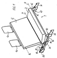
- Figures 1 to 5 each show in schematic perspective views the different Positions of a seat when being transferred from that in FIG. 1 shown use position in that shown in Fig. 5 Not in use or loading position.
- Fig. 6 shows 3 shows an enlarged illustration of the region VI in FIG. 3.
- the seat construction 1 consists of a seat part 2 (seat cushion) and a backrest hinged about a pivot axis 4 6.
- the seat part 2 is on the one hand via a transverse axis 8 foldable out, namely by an angle of about 180 °.
- the seat part 2 - in particular over the transverse axis 8 - connected to a sliding guide 10.
- This articulation and guidance of the seat part 2 is designed such that starting from the use position suitable for sitting (see Fig. 1) by moving and folding of the seat part 2 by approximately 180 ° relative to stationary guide parts and by pivoting the backrest 6 around an angle of about 90 ° relative to the seat part 2 of the entire seat with the backrest 6 and the seat part 2 in the non-use position illustrated in FIG. 5 is transferable, with the seat part 2 and the backrest 6 each with their lower or rear backs 2a and 6a essentially in a common loading level lie.
- the sequence of movements for transferring from the use position according to Fig.1 in the non-use position 5 or vice versa is shown in FIGS. 1 to 5 and the arrows shown clearly.
- additional guide means 12 are now of this type provided that the seat structure 1 - in addition to the leadership of the seat part 2 on the transverse axis 8 and Sliding guide 10 - also in the area of the pivot axis 4 between seat part 2 and backrest 6 during their transfer movements is always defined.
- the sliding guide 10 consists of two lateral, to each other parallel guide rails 14 which within the Vehicle stationary and essentially approximately horizontal and are arranged parallel to the longitudinal axis of the vehicle. With everyone Guide rail 14, a guide carriage 16 is slidable connected, the guide carriage 16 in the Side areas about the transverse axis 8 with pivoting the seat part 2 are connected. The one about the management tools 12 guided area of the seat part 2 with the backrest 6 connecting pivot axis 4 is in both positions (s.
- the guide means 12 are preferably by two lateral Swivel lever 18 formed, the one end in the area of Pivot axis 4, in particular coaxial to this, and articulated at other ends on stationary bearing elements 20 are.
- the bearing elements 20 are in one area arranged in the use position on the the seat part 2 opposite side (behind) the backrest 6 or in the non-use position in the area of the seat part 2 or in the vicinity of the guide carriage 16.
- Locking means for locking are expedient of seat part 2 and backrest 6 in their two different Positions provided. On the one hand it is about locking means not recognizable in the drawing, the in a joint 22 forming the pivot axis 4 (see Fig. 6) arranged between the seat part 2 and the backrest 6 are. These locking means are used in a manner known per se Way for releasably locking the backrest 6 in one certain or adjustable angle (variable backrest angle) relative to the seat part 2 in the use position. By unlocking this locking means can then fold the backrest 6 relative to the seat part 2.
- Bolt-like locking elements are also used as locking means 24 provided, on a rocker-like Section 26 extending beyond the pivot axis 4 the backrest 6.
- These locking elements 24 engage in the use position in slot-like bolt openings 28 from stationary Abutments 30 a.
- the slot shape of the bolt openings 28 is designed relative to the locking elements 24 so that when pivoting the backrest 6 backwards, the locking elements 24 automatically on a circular path in the corresponding engage shaped bolt openings 28. A release this lock is therefore by folding forward the backrest 6 in the direction of the arrow 32 according to FIG. 6 possible.
- the locking elements 24 are in the non-use position in the bearing recesses 34 Abutment 30.
- the bearing recesses 34 are in Adjustment direction offset to the bolt openings 28.
- the backrest 6 in their upper, i.e. lying away from the pivot axis 4 End region of lateral, bolt-like locking elements 36 on in the non-use position (see. Fig. 4 and 5) in slot-like bolt openings 38 in the front, stationary Engage the end region of the guide rails 14.
- the locking elements 36 in the Backrest 6 is retractable and in particular for actuation interact with a headrest bracket in such a way that with the headrest 40 mounted, the locking elements 36 held in its lowered position (Fig. 1) and by Disassembly of the headrest 40 automatically in their side projecting, ready-to-lock position are released.
- This Measure is advantageous for security reasons, because in the Use position Risk of accident and injury from laterally protruding parts can be avoided. Also have to anyway before transferring to the non-use position the headrests 40 are removed.
- At least one spring element or the like motor Power drive to support the movement when transferring between the use and non-use positions intended.
- This can be, for example are at least one gas pressure spring, e.g. on one bearing element 42 recognizable in the drawing figures at least can attack one of the two pivot levers 18. This results in particularly good ease of use, by unlocking the seat structure 1 practically automatically in the area of the pivot axis 4 is pressed at the top.
Landscapes
- Engineering & Computer Science (AREA)
- Aviation & Aerospace Engineering (AREA)
- Transportation (AREA)
- Mechanical Engineering (AREA)
- Seats For Vehicles (AREA)
Claims (12)
- Construction de siège (1) à fonction de rabattement, en particulier pour sièges arrière de véhicules automobiles, comprenant une partie assise (2) et un dossier (6) articulé de façon rabattable autour d'un axe de pivotement (4), la partie assise (2) étant reliée à un guide de coulissement (10) de façon à pouvoir être rabattue autour d'un axe transversal (8), de telle manière que, par coulissement et basculement de la partie assise (2) d'environ 180° par rapport à des parties de guidage fixes, ainsi que par pivotement du dossier (6) d'environ 90° par rapport à la partie assise (2), le dossier (6) et la partie assise (2) puissent être transférés d'une position d'utilisation appropriée pour la position assise à une position d'inutilisation, dans laquelle leurs faces respectivement inférieure et arrière (2a, 6a) soient étendues sensiblement dans un plan,
caractérisée par des moyens de guidage additionnels (12) de telle manière que la partie assise (2) et le dossier (6) soient guidés de façon définie, à peu près dans la région de l'axe de pivotement (4), pendant leurs mouvements de transfert entre la position d'utilisation et la position d'inutilisation. - Construction de siège selon la revendication 1,
caractérisée en ce que la région de l'axe de pivotement (4) peut être déplacée, sur une courbe de trajectoire définie, à l'aide des moyens de guidage (12), de telle manière que le transfert d'une position à l'autre puisse être exécuté en ne demandant qu'un minimum de place dans les régions de déplacement de la partie assise (2) et/ou du dossier (6). - Construction de siège selon la revendication 1 ou 2,
caractérisée en ce que le guide de coulissement (10) est constitué par des rails de guidage (14) fixes en position, essentiellement à peu près horizontaux, ainsi que par des coulisseaux de guidage (16) reliés à la partie assise (2) au moyen de l'axe transversal (8), la région de l'axe de pivotement (4) étant disposée dans une région à peu près centrale des coulisseaux de guidage (16) dans les deux positions de la partie assise (2) et du dossier (6), et pouvant se déplacer, à l'aide des moyens de guidage (12), sensiblement perpendiculairement aux rails de guidage (14), de telle manière que, lors du transfert, la région de l'axe de pivotement (4) s'éloigne à peu près verticalement des rails de guidage (14) et que la partie assise (2) puisse se déplacer avec le coulisseau de guidage (16) le long des rails de guidage (14) en se retournant simultanément d'environ 180°. - Construction de siège selon une des revendications 1 à 3,
caractérisée en ce que les moyens de guidage (12) sont formés par des leviers pivotants (18) qui sont articulés, à une extrémité, dans la région de l'axe de pivotement (4), en particulier plus précisément coaxialement à cet axe et, à l'autre extrémité, sur des éléments de palier (20) fixes en position. - Construction de siège selon la revendication 4,
caractérisée en ce que les éléments de palier (20) sont disposés dans une région qui se trouve sur le côté du dossier (6) qui est à l'opposé de la partie assise (2) dans la position d'utilisation et qui se trouve dans la région de la partie assise (2) dans la position d'inutilisation. - Construction de siège selon une des revendications 1 à 5,
caractérisée par des moyens de verrouillage destinés à bloquer la partie assise (2) et le dossier (6) dans leurs deux positions différentes. - Construction de siège selon une des revendications 1 à 6,
caractérisée en ce que, dans une articulation (22) entre la partie assise (2) et le dossier (6), qui forme l'axe de pivotement (4), sont disposés des moyens de verrouillage déverrouillables destinés à bloquer le dossier (6) de façon déblocable dans un angle déterminé, ou réglable par rapport à la partie assise (2), dans la position d'utilisation. - Construction de siège selon la revendication 6 ou 7,
caractérisée en ce que le dossier (6) présente, sur un segment (26) qui se prolonge au-delà de l'axe de pivotement (4) à la façon d'un fléau, des éléments de verrouillage (24) en forme de tourillons qui, dans la position d'utilisation, s'engagent dans des ouvertures de verrouillage (28) en forme de fentes appartenant à des butées (30) fixes en position. - Construction de siège selon la revendication 8,
caractérisée en ce que, dans la position d'inutilisation, les éléments de verrouillage (24) se trouvent dans des évidements de portée (34) des butées (30). - Construction de siège selon une des revendications 6 à 9,
caractérisée en ce que, dans sa région d'extrémité supérieure, éloignée de l'axe de pivotement (4), le dossier (6) présente des éléments de verrouillage latéraux (36) en forme de tourillons qui, dans la position d'inutilisation, s'engagent dans des ouvertures de verrouillage (38) en forme de fentes. - Construction de siège selon la revendication 10,
caractérisée en ce que les éléments de verrouillage (36) sont montés dans le dossier (6) de façon à pouvoir être escamotés et, pour l'actionnement, coopèrent en particulier avec un support d'appui-tête de telle manière que les éléments de verrouillage (36) soient maintenus dans leur position escamotée lorsque l'appui-tête (40) est monté et qu'ils soient libérés automatiquement sous l'effet du démontage de l'appui-tête (40) pour prendre leur position en saillie latérale, prête au verrouillage. - Construction de siège selon une des revendications 1 à 11,
caractérisée par au moins un élément d'entraínement à force destiné à assister le déroulement du mouvement lors du transfert entre les positions d'utilisation et d'inutilisation.
Applications Claiming Priority (2)
| Application Number | Priority Date | Filing Date | Title |
|---|---|---|---|
| DE29810326U | 1998-06-09 | ||
| DE29810326U DE29810326U1 (de) | 1998-06-09 | 1998-06-09 | Sitzkonstruktion mit Umklappfunktion für Kfz-Sitze |
Publications (2)
| Publication Number | Publication Date |
|---|---|
| EP0970843A1 EP0970843A1 (fr) | 2000-01-12 |
| EP0970843B1 true EP0970843B1 (fr) | 2004-04-14 |
Family
ID=8058306
Family Applications (1)
| Application Number | Title | Priority Date | Filing Date |
|---|---|---|---|
| EP99110986A Expired - Lifetime EP0970843B1 (fr) | 1998-06-09 | 1999-06-09 | Structure de siège avec fonction de rabattement pour siège d'automobile |
Country Status (2)
| Country | Link |
|---|---|
| EP (1) | EP0970843B1 (fr) |
| DE (2) | DE29810326U1 (fr) |
Families Citing this family (5)
| Publication number | Priority date | Publication date | Assignee | Title |
|---|---|---|---|---|
| DE102004005969B4 (de) * | 2004-02-06 | 2014-01-09 | GM Global Technology Operations LLC (n. d. Ges. d. Staates Delaware) | Sitz |
| DE102004041734B3 (de) * | 2004-08-28 | 2006-01-05 | Keiper Gmbh & Co.Kg | Fahrzeugsitz, insbesondere Kraftfahrzeugsitz |
| DE102009023014A1 (de) | 2009-05-28 | 2010-12-02 | Kiekert Ag | Fahrzeugsitz |
| DE102013002810A1 (de) | 2013-02-19 | 2014-08-21 | GM Global Technology Operations LLC (n. d. Gesetzen des Staates Delaware) | Fahrzeug mit einer Rücksitzanordnung |
| DE102013012604A1 (de) | 2013-07-29 | 2015-01-29 | GM Global Technology Operations LLC (n. d. Gesetzen des Staates Delaware) | Fahrzeug mit einer Rücksitzanordnung |
Family Cites Families (4)
| Publication number | Priority date | Publication date | Assignee | Title |
|---|---|---|---|---|
| US3171682A (en) * | 1963-09-23 | 1965-03-02 | Gen Motors Corp | Folding vehicle seats |
| DE1286415B (de) * | 1965-10-15 | 1969-01-02 | Hans Glas Gmbh Isaria Maschine | In eine oder mehrere Sitzbaenke umwandelbare Ladeflaeche fuer Fahrzeuge, insbesondere Kraftfahrzeuge |
| FR2411105A1 (fr) * | 1977-12-09 | 1979-07-06 | Peugeot | Siege transformable perfectionne pour vehicules automobiles |
| DE4422920A1 (de) * | 1994-06-30 | 1996-01-04 | Opel Adam Ag | Sitzanordnung, insbesondere für den Lade- bzw. Fahrgastraum eines Kraftfahrzeuges |
-
1998
- 1998-06-09 DE DE29810326U patent/DE29810326U1/de not_active Expired - Lifetime
-
1999
- 1999-06-09 DE DE59909146T patent/DE59909146D1/de not_active Expired - Fee Related
- 1999-06-09 EP EP99110986A patent/EP0970843B1/fr not_active Expired - Lifetime
Also Published As
| Publication number | Publication date |
|---|---|
| DE29810326U1 (de) | 1999-10-14 |
| EP0970843A1 (fr) | 2000-01-12 |
| DE59909146D1 (de) | 2004-05-19 |
Similar Documents
| Publication | Publication Date | Title |
|---|---|---|
| DE102009037816B3 (de) | Fahrzeugsitz, insbesondere Kraftfahrzeugsitz | |
| EP2001708B1 (fr) | Dispositif de declenchement d'un element tablette d'un systeme de siege pour vehicules de transport de personnes | |
| EP0689954B1 (fr) | Aménagement de siège, notamment pour le compartiment de chargement ou de passenger d'un véhicule automobile | |
| EP3092151A1 (fr) | Siège de véhicule | |
| WO2019096774A2 (fr) | Siège de véhicule à entrée facile | |
| DE102014107816A1 (de) | Nutzfahrzeugsitz mit arretierbarem Schlittenteil | |
| EP2920025A1 (fr) | Siège de véhicule, en particulier siège de véhicule automobile | |
| EP2601073B1 (fr) | Dispositif de fixation pour siège de véhicule et siège de véhicule | |
| EP2956333B1 (fr) | Ferrure à cran d'arrêt pour un siège de véhicule et siège de véhicule | |
| DE2640959C2 (de) | Kraftfahrzeugsitz, insbesondere Rücksitz für Kombi-Kraftfahrzeuge | |
| WO2014083051A1 (fr) | Siège de véhicule | |
| DE10012590B4 (de) | Vor einem Laderaum eines Kraftfahrzeuges angeordnete Sitzanordnung | |
| DE10139538C1 (de) | Fondsitz für Kraftfahrzeuge | |
| DE29810333U1 (de) | Sitzmodul | |
| DE2522074B2 (de) | Feststellvorrichtung für die Gleitführung eines in Längsrichtung verschiebbaren Kfz-Sitzes | |
| DE102007036450B3 (de) | Fahrzeugsitz, insbesondere Kraftfahrzeugsitz | |
| DE60113861T2 (de) | Fahrzeugsitzbereich zum Bewegen aus einer Benutzungspostion in eine Verstaupos ition | |
| WO2012022425A1 (fr) | Siège de véhicule automobile comprenant plusieurs ferrures | |
| DE102007063565A1 (de) | Kraftfahrzeugsitz | |
| DE69502143T2 (de) | Vorrichtung zum Schnellverbinden eines Kindersitzes mit einem Kraftwagensitz | |
| DE3329725C2 (fr) | ||
| DE19919698A1 (de) | Fahrzeugsitz, insbesondere Kraftfahrzeugsitz | |
| EP1762488A2 (fr) | Système de siège avec une unité de tablette pour véhicules de transport de personnes, en particulier pour aéronefs | |
| DE10145240B4 (de) | Kopfstütze für Fahrzeugsitze | |
| DE102008059355B4 (de) | Beschlagsystem für einen Fahrzeugsitz sowie Fahrzeugsitz mit einem solchen Beschlagsystem |
Legal Events
| Date | Code | Title | Description |
|---|---|---|---|
| PUAI | Public reference made under article 153(3) epc to a published international application that has entered the european phase |
Free format text: ORIGINAL CODE: 0009012 |
|
| AK | Designated contracting states |
Kind code of ref document: A1 Designated state(s): DE FR GB IT |
|
| AX | Request for extension of the european patent |
Free format text: AL;LT;LV;MK;RO;SI |
|
| EL | Fr: translation of claims filed | ||
| GBC | Gb: translation of claims filed (gb section 78(7)/1977) | ||
| 17P | Request for examination filed |
Effective date: 20000610 |
|
| AKX | Designation fees paid |
Free format text: DE FR GB IT |
|
| GRAP | Despatch of communication of intention to grant a patent |
Free format text: ORIGINAL CODE: EPIDOSNIGR1 |
|
| GRAS | Grant fee paid |
Free format text: ORIGINAL CODE: EPIDOSNIGR3 |
|
| GRAA | (expected) grant |
Free format text: ORIGINAL CODE: 0009210 |
|
| AK | Designated contracting states |
Kind code of ref document: B1 Designated state(s): DE FR GB IT |
|
| REG | Reference to a national code |
Ref country code: GB Ref legal event code: FG4D Free format text: NOT ENGLISH |
|
| REF | Corresponds to: |
Ref document number: 59909146 Country of ref document: DE Date of ref document: 20040519 Kind code of ref document: P |
|
| GBT | Gb: translation of ep patent filed (gb section 77(6)(a)/1977) |
Effective date: 20040723 |
|
| ET | Fr: translation filed | ||
| PLBE | No opposition filed within time limit |
Free format text: ORIGINAL CODE: 0009261 |
|
| STAA | Information on the status of an ep patent application or granted ep patent |
Free format text: STATUS: NO OPPOSITION FILED WITHIN TIME LIMIT |
|
| 26N | No opposition filed |
Effective date: 20050117 |
|
| PGFP | Annual fee paid to national office [announced via postgrant information from national office to epo] |
Ref country code: IT Payment date: 20080529 Year of fee payment: 10 |
|
| PGFP | Annual fee paid to national office [announced via postgrant information from national office to epo] |
Ref country code: DE Payment date: 20080630 Year of fee payment: 10 |
|
| PGFP | Annual fee paid to national office [announced via postgrant information from national office to epo] |
Ref country code: GB Payment date: 20080521 Year of fee payment: 10 |
|
| GBPC | Gb: european patent ceased through non-payment of renewal fee |
Effective date: 20090609 |
|
| REG | Reference to a national code |
Ref country code: FR Ref legal event code: ST Effective date: 20100226 |
|
| PG25 | Lapsed in a contracting state [announced via postgrant information from national office to epo] |
Ref country code: FR Free format text: LAPSE BECAUSE OF NON-PAYMENT OF DUE FEES Effective date: 20090630 |
|
| PGFP | Annual fee paid to national office [announced via postgrant information from national office to epo] |
Ref country code: FR Payment date: 20080513 Year of fee payment: 10 |
|
| PG25 | Lapsed in a contracting state [announced via postgrant information from national office to epo] |
Ref country code: GB Free format text: LAPSE BECAUSE OF NON-PAYMENT OF DUE FEES Effective date: 20090609 |
|
| PG25 | Lapsed in a contracting state [announced via postgrant information from national office to epo] |
Ref country code: DE Free format text: LAPSE BECAUSE OF NON-PAYMENT OF DUE FEES Effective date: 20100101 |
|
| PG25 | Lapsed in a contracting state [announced via postgrant information from national office to epo] |
Ref country code: IT Free format text: LAPSE BECAUSE OF NON-PAYMENT OF DUE FEES Effective date: 20090609 |