EP0970903A2 - Dispositif d'alimentation en papier pour une machine à imprimer - Google Patents
Dispositif d'alimentation en papier pour une machine à imprimer Download PDFInfo
- Publication number
- EP0970903A2 EP0970903A2 EP99112961A EP99112961A EP0970903A2 EP 0970903 A2 EP0970903 A2 EP 0970903A2 EP 99112961 A EP99112961 A EP 99112961A EP 99112961 A EP99112961 A EP 99112961A EP 0970903 A2 EP0970903 A2 EP 0970903A2
- Authority
- EP
- European Patent Office
- Prior art keywords
- jogger
- stack
- sheets
- paper
- paper feed
- Prior art date
- Legal status (The legal status is an assumption and is not a legal conclusion. Google has not performed a legal analysis and makes no representation as to the accuracy of the status listed.)
- Withdrawn
Links
- 238000007639 printing Methods 0.000 title claims abstract description 17
- 238000007645 offset printing Methods 0.000 description 2
Images


Classifications
-
- B—PERFORMING OPERATIONS; TRANSPORTING
- B65—CONVEYING; PACKING; STORING; HANDLING THIN OR FILAMENTARY MATERIAL
- B65H—HANDLING THIN OR FILAMENTARY MATERIAL, e.g. SHEETS, WEBS, CABLES
- B65H1/00—Supports or magazines for piles from which articles are to be separated
- B65H1/04—Supports or magazines for piles from which articles are to be separated adapted to support articles substantially horizontally, e.g. for separation from top of pile
-
- B—PERFORMING OPERATIONS; TRANSPORTING
- B65—CONVEYING; PACKING; STORING; HANDLING THIN OR FILAMENTARY MATERIAL
- B65H—HANDLING THIN OR FILAMENTARY MATERIAL, e.g. SHEETS, WEBS, CABLES
- B65H31/00—Pile receivers
- B65H31/34—Apparatus for squaring-up piled articles
- B65H31/38—Apparatus for vibrating or knocking the pile during piling
-
- B—PERFORMING OPERATIONS; TRANSPORTING
- B65—CONVEYING; PACKING; STORING; HANDLING THIN OR FILAMENTARY MATERIAL
- B65H—HANDLING THIN OR FILAMENTARY MATERIAL, e.g. SHEETS, WEBS, CABLES
- B65H2301/00—Handling processes for sheets or webs
- B65H2301/40—Type of handling process
- B65H2301/42—Piling, depiling, handling piles
- B65H2301/422—Handling piles, sets or stacks of articles
- B65H2301/4222—Squaring-up piles
-
- B—PERFORMING OPERATIONS; TRANSPORTING
- B65—CONVEYING; PACKING; STORING; HANDLING THIN OR FILAMENTARY MATERIAL
- B65H—HANDLING THIN OR FILAMENTARY MATERIAL, e.g. SHEETS, WEBS, CABLES
- B65H2801/00—Application field
- B65H2801/03—Image reproduction devices
- B65H2801/21—Industrial-size printers, e.g. rotary printing press
Definitions
- This invention relates to a paper feed device for a small sheet-fed offset printing press.
- a typical conventional small sheet-fed offset printing press comprises an elevator table on which are stacked sheets of paper, and a universal feeder for feeding the paper sheets one by one from the top of the stack into between feed rollers, which feed sheets into between an impression cylinder and a blanket cylinder for printing.
- An object of this invention is to provide a paper feed device for use in a printing press that permits accurate and easy lateral positioning of the stacked sheets of paper.
- a paper feed device for use in a printing press in which sheets of paper in a stack on a vertically movable table are fed one by one toward printing cylinders, the paper feed device comprising a positioning guide for positioning one side of the stack at its upper portion, a jogger movable toward and away from the other side of the stack, the positioning guide and the jogger being provided over the table, and a reciprocator for reciprocating the jogger relative to the other side of the stack.
- the reciprocator may comprise a cam mechanism driven by a motor or a mechanism comprising a threaded shaft mounted on the outer side of the jogger, a nut threaded on the threaded shaft, and a motor for turning the nut forward and backward.
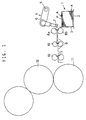
- Fig. 1 schematically shows the feeder-to-press segment of a printing press. It has a paper feed unit 1 including an elevator table 2 on which are stacked sheets of paper. The front face of the paper stack A is positioned by abutting against a front plate 3.
- a universal feeder 4 which comprises a shaft 5, an arm 6 mounted on the shaft 5, and a sucker 7 mounted at the free end of the arm 6.
- the arm is pivoted downward by rotating the shaft 5 counterclockwise to suck the paper sheet P at top of the stack A.
- the arm 6 is pivoted upward by rotating the shaft 5 clockwise to insert the sheet P into between a pair of feed rollers 8a and 8b.
- rollers 8a, 8b are being rotated in the directions shown by the arrows, so that the sheet P is fed forward.
- guide plates 9 for guiding sheets and feed rollers 10 are provided in the feed path of sheets. Sheets are fed by the feed rollers 10, which are rotated in the directions of arrows, into between an impression cylinder 11 and a blanket cylinder 12 for printing.
- the paper feed unit 1 has a lateral register device 20 for laterally registering paper sheets P at the upper part of the stack A.
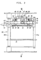
- the lateral register device 20 comprises a positioning guide 21 for positioning one side of the upper part of the stack A, a plate-shaped jogger 22 facing the other side of the stack A, and a reciprocator 30 for moving the jogger 22 toward and away from the other side of the stack 30.
- the positioning guide 21 is a plate member movable in the lateral direction of the sheets P as well as in the vertical direction, though this feature is not shown.
- the jogger 22 is movable laterally and vertically in line with the positioning guide 21.
- the mechanism for moving the jogger 22 laterally and vertically comprises a pair of elongate guide members 31a, 31b extending parallel to each other in the direction perpendicular to the feed direction of sheets P, a support plate 32 supported so as to be movable along the guide members 31a, 31b, and a pair of arms 33 arranged on the outer side of the support plate 32 in the feed direction of sheets.
- the arms 33 have their upper ends coupled to the support plate 32 by bolts 35 inserted through elongate holes 34 formed in the upper ends of the arms 33 and threaded into the support plate 32.
- the arms 33 carry at their bottom ends a jogger support plate 36 (Fig. 4) having guide sleeves 37 through which guide shafts 38 secured to the outer surface of the jogger 22 slidably extend.
- a jogger support plate 36 (Fig. 4) having guide sleeves 37 through which guide shafts 38 secured to the outer surface of the jogger 22 slidably extend.
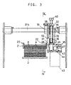
- the reciprocator 30 for reciprocating the jogger 22 toward and away from the paper stack A comprises, as shown in Figs. 3 and 4, a motor 43 mounted to the bottom surface of a motor support plate 42 secured to the bottom of the jogger support plate 36, and a cam 45 fixed to the rotary shaft 44 of the motor 43.
- the motor support plate 42 has on its top surface a shaft 46 which pivotably supports the central portion of an arm 47 carrying at one end thereof a cam follower 48 in contact with the cam 45 and at the other end another cam follower 49 abetting the tip of one of the guide shafts 38.
- Springs 50 are mounted around the respective guide shafts 38 to urge the shafts 38 so as to keep the cam follower 48 always in contact with the cam 45.
- the jogger 22 can thus be reciprocated by turning the cam 45.
- the jogger 22 When the cam 45 is turned by the motor 43, the jogger 22 is reciprocated. While advancing, the jogger 22 pushes sheets P at the upper part of the stack A against the positioning guide 21, thus laterally positioning them simultaneously.
- sheets are laterally positioned one at a time, sheets may be deformed in the width direction. This makes accurate lateral positioning difficult. In the present arrangement, since a plurality of sheets are positioned simultaneously, sheets are less likely to be deformed in the width direction, so that sheets can be positioned with extremely high register accuracy.
- a stepping motor is preferably used as the motor 43 for driving the cam 45 to synchronize the lateral positioning of sheets with the feeding motion of the universal feeder 4.
- a guide plate 51 having a window 52 through which the jogger 22 can pass may be provided so as to be slidable along the guide members 31a, 31b and fixable at any desired position.
- Figs. 6-8 show different embodiments of reciprocator 30 for reciprocating the jogger 22.
- the reciprocator 30 shown in Fig. 6 includes a roller arm 53 mounted on the outer side of the jogger 22, a cam follower 54 mounted on the top end of the arm 53, and springs 50 mounted around the guide shafts 38 for urging the cam 45 into contact with the cam follower 54.
- the jogger 22 is thus directly reciprocated by the rotating cam 45.
- the reciprocator 30 shown in Fig. 7 includes a threaded shaft 55 provided at the outer side of the jogger 22, a nut 56 threaded onto the threaded shaft 55 and rotatably supported by a bearing 58 mounted in a housing 57, and a motor 59 for reciprocating the jogger 22 by turning the nut 56 alternately forward and backward.
- the reciprocator 30 shown in Fig. 8 includes a nut 60 fixed to the outer side of the jogger 22, a threaded shaft 61 threaded into the nut 60, and a motor 62 for reciprocating the jogger 22 by turning the threaded shaft 61 alternately forward and backward.
- sheets stacked on the table can be laterally positioned easily and efficiently and can be printed with high register accuracy.
Landscapes
- Engineering & Computer Science (AREA)
- Mechanical Engineering (AREA)
- Sheets, Magazines, And Separation Thereof (AREA)
- Registering Or Overturning Sheets (AREA)
Applications Claiming Priority (2)
| Application Number | Priority Date | Filing Date | Title |
|---|---|---|---|
| JP19177798 | 1998-07-07 | ||
| JP19177798A JP2000016599A (ja) | 1998-07-07 | 1998-07-07 | 印刷機の給紙装置 |
Publications (2)
| Publication Number | Publication Date |
|---|---|
| EP0970903A2 true EP0970903A2 (fr) | 2000-01-12 |
| EP0970903A3 EP0970903A3 (fr) | 2000-12-13 |
Family
ID=16280371
Family Applications (1)
| Application Number | Title | Priority Date | Filing Date |
|---|---|---|---|
| EP99112961A Withdrawn EP0970903A3 (fr) | 1998-07-07 | 1999-07-05 | Dispositif d'alimentation en papier pour une machine à imprimer |
Country Status (2)
| Country | Link |
|---|---|
| EP (1) | EP0970903A3 (fr) |
| JP (1) | JP2000016599A (fr) |
Cited By (4)
| Publication number | Priority date | Publication date | Assignee | Title |
|---|---|---|---|---|
| EP1944256A3 (fr) * | 2007-01-15 | 2009-11-18 | Heidelberger Druckmaschinen Aktiengesellschaft | Dispositif et procédé destinés à aligner des piles de feuilles |
| EP2019058A3 (fr) * | 2007-07-27 | 2011-03-23 | Komori Corporation | Procédé d'ajustement de position et appareil d'ajustement de portion cible dans une machine de traitement de feuille |
| US9079732B1 (en) | 2014-01-21 | 2015-07-14 | Xerox Corporation | Sheet registration using orbital tampers |
| CN107792690A (zh) * | 2017-12-11 | 2018-03-13 | 天津市茂海永泰纸制品有限公司 | 一种高效胶印机送纸装置 |
Families Citing this family (1)
| Publication number | Priority date | Publication date | Assignee | Title |
|---|---|---|---|---|
| US7501703B2 (en) | 2003-02-28 | 2009-03-10 | Knowles Electronics, Llc | Acoustic transducer module |
Family Cites Families (5)
| Publication number | Priority date | Publication date | Assignee | Title |
|---|---|---|---|---|
| US4047713A (en) * | 1973-08-10 | 1977-09-13 | Norfin, Inc. | Sheet jogger |
| DE2939267A1 (de) * | 1979-09-28 | 1981-04-02 | Mabeg Maschinenbau Gmbh Nachf. Hense & Pleines Gmbh & Co, 6050 Offenbach | Vorrichtung zum selbsttaetigen seitlichen ausrichten eines auf einer tragplatte ruhenden bogenstapels |
| DE2942855C2 (de) * | 1979-10-24 | 1983-06-09 | Automation für grafische Technik AG, 4005 Meerbusch | Stapeleinrichtung insbesondere für Druckmaschinen |
| DE3426852A1 (de) * | 1983-07-20 | 1985-02-07 | Ricoh Co., Ltd., Tokio/Tokyo | Blattausrichteinrichtung |
| DE4322561C2 (de) * | 1993-07-07 | 1996-01-18 | Heidelberger Druckmasch Ag | Bogengeradstoßvorrichtung |
-
1998
- 1998-07-07 JP JP19177798A patent/JP2000016599A/ja active Pending
-
1999
- 1999-07-05 EP EP99112961A patent/EP0970903A3/fr not_active Withdrawn
Cited By (6)
| Publication number | Priority date | Publication date | Assignee | Title |
|---|---|---|---|---|
| EP1944256A3 (fr) * | 2007-01-15 | 2009-11-18 | Heidelberger Druckmaschinen Aktiengesellschaft | Dispositif et procédé destinés à aligner des piles de feuilles |
| US7658378B2 (en) | 2007-01-15 | 2010-02-09 | Heidelberger Druckmaschinen Ag | Apparatus and method for aligning sheet stacks and sheet processing machine having the apparatus |
| EP2019058A3 (fr) * | 2007-07-27 | 2011-03-23 | Komori Corporation | Procédé d'ajustement de position et appareil d'ajustement de portion cible dans une machine de traitement de feuille |
| US9079732B1 (en) | 2014-01-21 | 2015-07-14 | Xerox Corporation | Sheet registration using orbital tampers |
| CN107792690A (zh) * | 2017-12-11 | 2018-03-13 | 天津市茂海永泰纸制品有限公司 | 一种高效胶印机送纸装置 |
| CN107792690B (zh) * | 2017-12-11 | 2023-06-20 | 天津市茂海永泰纸制品有限公司 | 一种高效胶印机送纸装置 |
Also Published As
| Publication number | Publication date |
|---|---|
| JP2000016599A (ja) | 2000-01-18 |
| EP0970903A3 (fr) | 2000-12-13 |
Similar Documents
| Publication | Publication Date | Title |
|---|---|---|
| US8720336B2 (en) | Plate for magnet cylinder | |
| US4402266A (en) | Front lay device for sheet-fed rotary printing presses | |
| US6877430B2 (en) | Gripper device in a sheet-processing machine | |
| EP2059468A1 (fr) | Dispositif d'alignement | |
| JPH0126978B2 (fr) | ||
| DE102018219708B3 (de) | Bogenverarbeitende Maschine | |
| CN101412311B (zh) | 用于将印版供给到印刷机的印版滚筒的装置 | |
| JPS63242829A (ja) | 印刷機の紙差し装置 | |
| US20070231091A1 (en) | Plate mounting cylinder | |
| US4627609A (en) | Sheet delivery device, especially for small offset printing machine | |
| JP4160680B2 (ja) | 枚葉紙輪転印刷機における律動的な見当誤差を取り除く方法およびこの方法を実施するための装置 | |
| US5240244A (en) | Process and apparatus for prestacking in a sheet feeder of rotary printing presses | |
| DE3438134C2 (fr) | ||
| EP1842670B1 (fr) | Dispositif de guidage de plaque | |
| JP2000016599A (ja) | 印刷機の給紙装置 | |
| ATE151380T1 (de) | Zuführvorrichtung für bogendruckmaschine | |
| US6546863B2 (en) | Machine for processing printing-material sheets | |
| EP1136262B1 (fr) | Dispositif pour l'actionnement d'une pince préliminaire | |
| EP4037905B1 (fr) | Machine d'impression ayant un dispositif pour détecter la présence d'un cliché d'application et procédé d'alimentation d'un cliché d'application | |
| JP2866037B2 (ja) | 輪転印刷機のための枚葉紙引き渡し胴 | |
| US6446959B2 (en) | Device for aligning sheets laterally | |
| US4526364A (en) | Sheet feeding mechanism for duplicating machine with duplexing capability | |
| GB2096543A (en) | Adjustments in printing presses | |
| WO2002085765A1 (fr) | Dispositif d'enregistrement pour systeme de collecte de feuilles | |
| JPH01133740A (ja) | 印刷対象物の見当合せ装置 |
Legal Events
| Date | Code | Title | Description |
|---|---|---|---|
| PUAI | Public reference made under article 153(3) epc to a published international application that has entered the european phase |
Free format text: ORIGINAL CODE: 0009012 |
|
| AK | Designated contracting states |
Kind code of ref document: A2 Designated state(s): DE FR GB |
|
| AX | Request for extension of the european patent |
Free format text: AL;LT;LV;MK;RO;SI |
|
| PUAL | Search report despatched |
Free format text: ORIGINAL CODE: 0009013 |
|
| AK | Designated contracting states |
Kind code of ref document: A3 Designated state(s): AT BE CH CY DE DK ES FI FR GB GR IE IT LI LU MC NL PT SE |
|
| AX | Request for extension of the european patent |
Free format text: AL;LT;LV;MK;RO;SI |
|
| 17P | Request for examination filed |
Effective date: 20010412 |
|
| AKX | Designation fees paid |
Free format text: DE FR GB |
|
| 17Q | First examination report despatched |
Effective date: 20011108 |
|
| STAA | Information on the status of an ep patent application or granted ep patent |
Free format text: STATUS: THE APPLICATION IS DEEMED TO BE WITHDRAWN |
|
| 18D | Application deemed to be withdrawn |
Effective date: 20020319 |