EP0971096A2 - Fixation d'une aube à un rotor - Google Patents
Fixation d'une aube à un rotor Download PDFInfo
- Publication number
- EP0971096A2 EP0971096A2 EP99304677A EP99304677A EP0971096A2 EP 0971096 A2 EP0971096 A2 EP 0971096A2 EP 99304677 A EP99304677 A EP 99304677A EP 99304677 A EP99304677 A EP 99304677A EP 0971096 A2 EP0971096 A2 EP 0971096A2
- Authority
- EP
- European Patent Office
- Prior art keywords
- rotor
- groove
- portions
- root
- groove portions
- Prior art date
- Legal status (The legal status is an assumption and is not a legal conclusion. Google has not performed a legal analysis and makes no representation as to the accuracy of the status listed.)
- Granted
Links
Images


Classifications
-
- F—MECHANICAL ENGINEERING; LIGHTING; HEATING; WEAPONS; BLASTING
- F01—MACHINES OR ENGINES IN GENERAL; ENGINE PLANTS IN GENERAL; STEAM ENGINES
- F01D—NON-POSITIVE DISPLACEMENT MACHINES OR ENGINES, e.g. STEAM TURBINES
- F01D5/00—Blades; Blade-carrying members; Heating, heat-insulating, cooling or antivibration means on the blades or the members
- F01D5/30—Fixing blades to rotors; Blade roots ; Blade spacers
- F01D5/3007—Fixing blades to rotors; Blade roots ; Blade spacers of axial insertion type
Definitions
- the present invention relates generally to a rotor assembly, particularly to a rotor assembly for a gas turbine engine, more particularly to a fan rotor assembly for a turbofan gas turbine engine.
- Turbofan gas turbine engines comprise a fan rotor assembly, positioned at the upstream end of a core gas generator, which provides thrust and supplies air to the core gas generator of the turbofan gas turbine engine.
- the fan rotor assembly comprises a rotor hub and a plurality of circumferentially spaced radially extending fan blades.
- the rotor hub has a plurality of generally axially extending grooves in its periphery and the roots of the fan blades locate and are retained in the grooves.
- the axially extending grooves have a dovetail cross-section and each of the fan blades has a correspondingly shaped dovetail cross-section root.
- each axially extending groove is arranged in a plane parallel with the axis of the turbofan gas turbine engine and the base of each fan blade root is also arranged in a plane parallel with the axis of the turbofan gas turbine engine.
- each axially extending groove is also arranged at an incline to the axis of the turbofan gas turbine engine.
- each fan blade has a single root which locates in a single corresponding axial groove in the periphery of the fan rotor assembly.
- each rotor blade with a plurality of axially spaced root portions which locate in a plurality of axially spaced groove portions on the periphery of a single rotor disc.
- the base of each groove is arranged in a plane parallel to the axis of the gas turbine engine.
- each fan blade with two axially spaced root portions which locate in two axially spaced groove portions on the periphery of a single fan disc.
- the base portions of the two axially spaced root portions are inclined to the axis of the gas turbine engine but with opposite inclines so that they are radially convergent with respect to the axis of the gas turbine engine.
- the base portions of the two axially extending grooves are also convergent with respect to the axis of the gas turbine engine.
- the present invention seeks to provide a novel rotor assembly for a gas turbine engine which provides improved retention of the rotor blades on the rotor.
- the present invention provides a rotor assembly comprising a rotor having a hub and a plurality of circumferentially spaced radially extending rotor blades, the hub having a plurality of circumferentially spaced axially extending grooves in its periphery, each groove being arranged to receive the root of a corresponding one of the rotor blades, each groove having at least three axially spaced groove portions, each rotor blade having a corresponding number of axially spaced root portions, each groove portion being arranged to receive a corresponding root portion of the corresponding one of the rotor blades, each groove portion having at least two circumferentially extending flanks, each root portion having at least two circumferentially extending flanks, at least the flanks of two of the root portions of each rotor blade being inclined to the axis of the rotor in one sense, at least the flanks of one of the root portions of each rotor blade being inclined to the axis of the rotor in the opposite
- the radius of the hub being smaller at a first axial end of the rotor than at a second axial end of the rotor such that the radii of the bases of the groove portions progressively increase from the first axial end of the rotor to the second axial end of the rotor.
- the bases of the groove portions being inclined to the axis of the rotor such that the radius of the base of each groove portion increases from the first axial end of the groove portion to the second axial end of the groove portion, at least two of the bases of the root portions of each rotor blade being inclined to the axis of the rotor in one sense, at least one of the bases of the root portions of each rotor blade being inclined to the axis of the rotor in the opposite sense.
- each groove has an even number of axially spaced groove portions
- each rotor blade has a corresponding number of axially spaced root portions.
- each groove has four axially spaced groove portions
- each rotor blade has four axially spaced root portions.
- all the groove portions have equal lengths, half of the number of groove portions are inclined at the same angle in one sense to the axis of the rotor and half of the number of groove portions are inclined at the same angle but in the opposite sense.
- all the groove portions are inclined at an angle between 15° and 18°. Preferably all the groove portions are inclined at an angle of 16.4°.
- the groove portions have different lengths, half of the number of groove portions are inclined at different angles in one sense to the axis of the rotor and half of the number of groove portions are inclined at different angles but in the opposite sense.
- each of the axially extending groove portions has a dovetail cross-section and each of the rotor portions has a correspondingly shaped dovetail cross-section.
- the rotor comprises a plurality of axially spaced discs, the hub of each disc having one of the root portions.
- the hubs of adjacent discs are interconnected.
- the hubs of adjacent discs are interconnected by a welded joint.
- the rotor may comprise a plurality of axially spaced discs, the hub of each disc having at least two of the root portions.
- the rotor is a fan rotor and the blades are fan blades.
- the rotor is a gas turbine rotor and the blades are gas turbine blades.
- the present invention also provides a rotor blade comprising an aerofoil and a root, the aerofoil having a leading edge, a trailing edge, a convex surface and a concave surface, the leading edge and trailing edge extending in a first direction longitudinally of the rotor blade, the root having at least three root portions spaced apart in a second direction extending between the leading edge and the trailing edge of the aerofoil, each root portion having at least two flanks extending transversely to the first direction and transversely to the second direction, at least the flanks of two of the root portions being inclined to the second direction in one sense, at least the flanks of one of the root portions being inclined to the second direction in the opposite sense.
- the present invention also provides a rotor having a hub, the hub having a plurality of circumferentially spaced axially extending grooves in its periphery, each groove having at least three axially spaced groove portions, each groove portion having at least two circumferentially extending flanks, at least the flanks of two of the groove portions of each groove being inclined to the axis of the rotor in one sense and at least the flanks of one of the groove portions of each groove being inclined to the axis of the rotor in the opposite sense.
- the radius of the hub being smaller at a first axial end of the rotor than at a second axial end of the rotor such that the radii of the bases of the groove portions progressively increase from the first axial end of the rotor to the second axial end of the rotor.
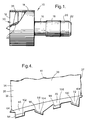
- Figure 1 is a view of a turbofan gas turbine engine having a rotor assembly according to the present invention.
- Figure 2 is an enlarged longitudinal cross-sectional view through the rotor assembly shown in figure 1, showing the rotor and the root of a rotor blade.
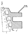
- Figure 3 is a cross-sectional view through the rotor shown in figure 2.
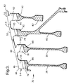
- Figure 4 is a cross-sectional view through the root of a rotor blade shown in figure 2.
- Figure 5 is a cross-sectional view showing one stage in the installation of a rotor blade in the rotor to form the rotor assembly shown in figure 2.
- Figure 6 is a cross-sectional view showing a second stage in the installation of a rotor blade in the rotor to form the rotor assembly shown in figure 2.
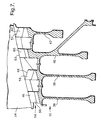
- Figure 7 is an enlarged longitudinal cross-sectional view through an alternative embodiment of the rotor assembly shown in figure 1.
- Figure 8 is an enlarged longitudinal cross-sectional view through another embodiment of the rotor assembly shown in figure 1.
- Figure 9 is an enlarged longitudinal cross-sectional view through a further alternative embodiment of rotor assembly shown in figure 1.
- Figure 10 is an enlarged longitudinal cross-sectional view through a further alternative embodiment of rotor assembly shown in figure 1.
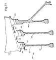
- Figure 11 is an enlarged longitudinal cross-sectional view through a further alternative embodiment of rotor assembly shown in figure 1.
- Figure 12 is a perspective view of the root of the rotor blade shown in figure 4.
- a turbofan gas turbine engine 10 shown in figure 1, comprises in axial flow series an inlet 12, a fan section 14, a compressor section 16, a combustion chamber assembly 18, a turbine section 20 and an exhaust 22.
- the turbine section 20 is arranged to drive the fan section 14 and the compressor section 16 via one or more shafts (not shown).
- the operation of the turbofan gas turbine engine 10 is quite conventional and will not be discussed further.
- the fan section 14, as shown more clearly in figures 2, 3 and 4 comprises a fan rotor assembly 30 which comprises a fan rotor 32 and a plurality of equi-circumferentially spaced radially outwardly extending fan blades 34.
- the fan rotor 32 comprises a plurality of axially spaced rotor discs 36, 38, 40 and 42 and adjacent rotor discs 36, 38, 40 and 42 are interconnected to form the fan rotor 32.
- the fan rotor 32 has a hub 44 defined by the hubs 46, 48, 50 and 52 of the rotor discs 36, 38, 40 and 42 respectively.
- the adjacent rotor discs 36, 38, 40 and 42 are interconnected, by laser or electron beam welded joints, at the hub 44 to form the fan rotor 32.
- the hub 44 is provided with a plurality of equi-circumferentially spaced axially extending grooves 54.
- Each of the axially extending grooves 54 comprises a plurality of axially spaced groove portions 56, 58, 60 and 62.
- the groove portions 56, 58, 60 and 62 are in the hubs 46, 48, 50 and 52 of the rotor discs 36, 38, 40 and 42 respectively.
- Each fan blade 34 comprises an aerofoil 33 and a root 64.
- Each aerofoil 33 has a leading edge 35, a trailing edge 37, a convex surface 39 and a concave surface 41.
- the leading edge 35 and the trailing edge 37 of each fan blade 34 extend longitudinally of the fan blade 34.
- Each root 64 comprises a plurality of axially spaced root portions 66, 68, 70 and 72 equal in number to the number of groove portions 56, 58, 60 and 62.
- the axial spacing between each of the adjacent root portions 66, 68, 70 and 72 is the same as the corresponding axial spacing between adjacent groove portions 56, 58, 60 and 62.
- the root portions 66, 68, 70 and 72 are thus spaced apart in the straight line interconnecting the leading edge 35 and the trailing edge 37 of the aerofoil 33, this is more commonly termed the chord line.
- Each groove portion 56, 58, 60 and 62 has a dovetail cross-section and therefore each groove portion 56, 58, 60 and 62 has two circumferentially extending flanks 74, 76, 78 and 80 respectively.
- Each groove portion 56, 58, 60 and 62 has a base 86, 88, 90 and 92 respectively.
- the flanks 74, 76, 78 and 80 intersect with the bases 86, 88, 90 and 92 to define the dovetail cross-section groove portions 56, 58, 60 and 62.
- flanks 74 and 78 of two of the groove portions 56 and 60 of each groove 54 are inclined to the axis X of the rotor 32 at an angle ⁇ in one sense such that the flanks 74 and 78 of groove portions 56 and 60 respectively increase in radius from the first axial, upstream, end of the respective groove portion 56 and 60 to the second axial, downstream, end of the respective groove portion 56 and 60.
- flanks 76 and 80 of two of the groove portions 58 and 62 of each groove 54 are inclined to the axis X of the rotor 32 at an angle ⁇ in the opposite sense such that the flanks 76 and 80 of groove portions 58 and 62 respectively increase in radius from the second axial, downstream, end of the respective groove portion 58 and 62 to the first axial, upstream, end of the respective groove portion 58 and 62.
- the radius of the hub 44 is greater at a second axial,° downstream, end 82 of the rotor 32 than at a first axial, upstream, end 84 of the rotor 32 such that the radii R1, R2, R3 and R4 of the bases 86, 88, 90 and 92 of the groove portions 56, 58, 60 and 62 respectively progressively increase from the first axial, upstream, end 82 of the rotor 32 to the second axial, downstream, end 84 of the rotor 32.
- the bases 86, 88, 90 and 92 of the groove portions 56, 58, 60 and 62 respectively are inclined to the axis X of the rotor 32 also at an angle ⁇ such that the radius of the bases 86, 88, 90 and 92 of each groove portion 56, 58, 60 and 62 respectively increases from the first axial, upstream, end of the respective groove portion 56, 58, 60 and 62 to the second axial, downstream, end of the respective groove portion 56, 58, 60 and 62.
- Each root portion 66, 68, 70 and 72 has a dovetail cross-section and therefore each root portion 66, 68, 70 and 72 has two circumferentially extending flanks 94, 96, 98 and 100 respectively.
- Each root portion 66, 68, 70 and 72 has a base 102, 104, 106 and 108 respectively.
- the flanks 94, 96, 98 and 100 intersect with the bases 102, 104, 106 and 108 to define the dovetail cross-section root portions 66, 68, 70 and 72.
- flanks 94 and 98 of two of the root portions 66 and 70 of each rotor blade 34 are inclined to the axis X of the rotor 32 at an angle ⁇ in one sense such that the flanks 94 and 98 of root portions 66 and 70 respectively increase in radius from the first axial, upstream, end of the respective root portion 66 and 70 to the second axial, downstream, end of the respective root portion 66 and 70.
- flanks 96 and 100 of two of the root portions 68 and 70 of each rotor blade 34 are inclined to the axis X of the rotor 32 at an angle ⁇ in the opposite sense such that the flanks 96 and 100 of root portions 68 and 72 respectively increase in radius from the second axial, downstream, end of the respective root portion 68 and 72 to the first axial, upstream, end of the respective root portion 68 and 72.
- the bases 102 and 106 of two of the root portions 66 and 70 of each rotor blade 34 are inclined to the axis X of the rotor 32 at an angle ⁇ in one sense such that the bases 102 and 104 of root portions 66 and 70 respectively increase in radius from the first axial, upstream, end of the respective root portion 66 and 70 to the second axial, downstream, end of the respective root portion 66 and 70.
- the bases 104 and 108 of two of the root portions 68 and 72 of each rotor blade 34 are inclined to the axis X of the rotor 32 at an angle ⁇ in the opposite sense such that the bases 104 and 108 of root portions 68 and 72 respectively increase in radius from the second axial, downstream, end of the respective root portion 68 and 72 to the first axial, upstream, end of the respective root portion 68 and 72.
- the axial spacing between the rotor discs 36 and 38 is greater than the axial length of the root portions 68, the axial spacing between the rotor discs 38 and 40 is greater than the axial length of the root portions 70 and the axial spacing between the rotor discs 40 and 42 is greater than the axial length of the root portions 72.
- Each fan blade 34 is loaded onto the fan rotor 32, as shown more clearly in figures 5 and 6, by firstly moving the fan blade 34 radially inwardly into the corresponding groove 54 such that the root portion 66 is located axially upstream of the groove portion 56 of the rotor disc 36, and the root portions 68, 70 and 72 are located axially between the adjacent groove portions 58, 60 and 62 of the rotor discs 38, 40 and 42 respectively. Then secondly the fan blade 34 is moved axially in a downstream direction with a component in a radially outward direction such that the root portions 66, 68, 70 and 72 move axially into the corresponding groove portions 56, 58, 60 and 62 respectively.
- the inclined bases 86, 88, 90 and 92 of the groove portions 56, 58, 60 and 62 allow the oppositely inclined flanks 94, 96, 98 and 100 of the root portions 66, 68, 70 and 72 respectively to move axially into the corresponding groove portions 56, 58, 60 and 62.
- Each fan blade 34 is unloaded from the fan rotor 32, for replacement or repair, by firstly moving the fan blade 34 axially in an upstream direction with a component in a radially inward direction such that the root portions 66, 68, 70 and 72 move axially out of the corresponding groove portions 56, 58, 60 and 62 respectively. Then secondly the fan blade 34 is moved radially outwardly out of the corresponding groove 54.
- the roots 44 of the fan blades 34 are located in the groove 54 of the fan rotor 32 by the design of the four root portions 66, 68, 70 and 72 and the corresponding four groove portions 56, 58, 60 and 62.
- the fan blades 34 In operation, when the fan rotor 32 is rotating, the fan blades 34 generate reaction loads between the flanks 94, 96, 98 and 100 of the root portions 66, 68, 70 and 72 and the flanks 74, 76, 78 and 80 of the groove portions 56, 58, 60 and 62.
- the eight flanks are arranged to generate equal and opposite forces in all directions, so that there is no resultant force to cause the fan blades 34 to move.
- any forces applied to the fan blades 34 by aerodynamic loading, foreign object impact and fan blade off situations do not displace the fan blades 34 from its assembled position because the fan blades 34 may only be removed by movement in an axial upstream direction with a component in the radially inward direction.
- the centrifugal force applied to the fan blades 34 during operation is far greater than the resolved radial component of the previously mentioned forces, so that it is very difficult to move the fan blade 34 without failure of the root. It may be possible for the fan blades 34 to move under very large loads, however, the distance moved will be relatively small because the energy of the load is absorbed in movement against the centrifugal force.
- the main advantages of the fan rotor assembly is that the use of the two pairs of root portions on the fan blades and two pairs of groove portions on the rotor with oppositely inclined flanks on the root portions and groove portions provides a more positive axial location of the fan blades than that described in European patent application no. EP0821133A.
- the fan blades are fully located axially, circumferentially and radially by the design of the root portions and groove portions at all engine speeds above about 40rpm without the requirement for conventional blade locking features. This eliminates the weight and cost of the conventional blade locking features.
- location of the fan blades is provided by conventional fan blade chocking.
- a further advantage of the fan rotor assembly is that the method of assembly allows the volume of space in two of the groove portions 56 and 60 to be reduced by a greater degree than is possible with conventional root and groove arrangements, bringing a further weight reduction.
- Another advantage is that the root portions are at increasing radial distances from the axis of rotation, this reduces the weight of the fan blades and brings the additional advantages of reduced fan blade energy if the fan blade should become detached and reduced vibration of the fan rotor if a fan blade should become detached.
- the reduced fan blade energy if a fan blade becomes detached from the fan rotor enables the fan blade containment system in the fan casing to be made lighter and cheaper.
- the fan rotor may be made from a plurality of forged fan discs, bringing a further reduction in weight and cost.
- root portions are at increasing radial distances from the axis of rotation, is that the groove portions are also at increasing radial distances and this allows the circumferential width of the groove portions and root portions to be increased and the axial length of the groove portions and root portions to be decreased as the radial distance increases.
- the axial lengths of the individual root portions need not necessarily be equal and the angles of inclination need not necessarily be the same.
- the lengths of the individual root portions may be tailored to allow for the position of the forces acting on the fan blades.
- the lengths and angles of inclination of the flanks are chosen to generate equal and opposite forces in all directions so that there is no resultant force.
- the angles of inclination of the flanks to the axis are preferably chosen to be the same as the angle of inclination of the inner wall of the flow through the fan section.
- FIG 7 Another embodiment of the invention is shown in figure 7, which is substantially the same as that shown in figure 2 and like numerals denote like parts, but the adjacent rotor discs 36, 38, 40 and 42 are interconnected, by laser or electron beam welded joints, at some radial distance from the hub 44 to form the fan rotor 32.
- FIG 8 A further embodiment of the invention is shown in figure 8, which is similar to that shown in figure 2 and like numerals denote like parts, but the rotor 32 comprises two rotor discs 36B and 38B, rotor disc 36B has two hubs 46 and 48 which have the groove portions 56 and 58 and rotor disc 38B has two hubs 50 and 52 which have the groove portions 60 and 62.
- FIG 9 A further embodiment of the invention is shown in figure 9, which is similar to that shown in figure 2 and like numerals denote like parts, but the rotor 32 comprises a single rotor disc 36C, rotor disc 36C has all four hubs 46, 48, 50 and 52 which have the groove portions 56, 58, 60 and 62.
- FIG 10 A further embodiment of the invention is shown in figure 10, which is similar to that shown in figure 2 and like numerals denote like parts, but the rotor 32 comprises only three rotor discs 38, 40 and 42 and the rotor discs 38, 40 and 42 have hubs 48, 50 and 52 which have the groove portions 58, 60 and 62.
- the fan blades 34 have only three root portions 68, 70 and 72.
- FIG 11 A further embodiment of the invention is shown in figure 11, which is similar to that shown in figure 10 and like numerals denote like parts, but the rotor 32 comprises only three rotor discs 36, 38 and 40 and the rotor discs 36, 38, and 40 have hubs 46, 48 and 50 which have the groove portions 56, 58 and 60.
- the fan blades 34 have only three root portions 66, 68 and 70.
- root portions 68 and 72 have described the root portions 68 and 72 as having bases 104 and 108 inclined in an opposite direction to the bases 102 and 106 of root portions 66 and 70 it may be possible to have them inclined in the same direction, however this has the disadvantage of adding weight to the fan blades 34.
- flanks 102 and 104 are radially convergent and the flanks 106 and 108 are radially convergent.
- bases 102 and 104 are radially convergent and the bases 106 and 108 are radially convergent.
- flanks 74 and 76 of the groove portions 56 and 58 are radially convergent and the flanks 78 and 80 of the groove portions 60 and 62 are radially convergent.
- the invention has been described with reference to a rotor which has an increase in the hub from the first axial, upstream, end to the second axial, downstream end, it is also possible to use the invention on a rotor which has a uniform radius of the hub from the first axial, upstream, end to the second axial, downstream, end of the rotor with corresponding changes to the fan blades.
- the groove portions on the rotor are at substantially the same radial distance from the axis of the rotor and the root portions on the fan blades are at substantially the same radial distance from the axis of the rotor.
- the invention is applicable to other rotor assemblies, for example compressor blades and turbine blades or propeller blades.
- the invention has been described with reference to the use of four root portions and four groove portions, but the invention is applicable to three or more root portions and groove portions.
- the invention has been described with reference to dovetail cross-section root and groove portions, it is also applicable to other cross-sections of root and groove portions, for example a fir tree cross-section.
- the fan blade root portions, and the rotor groove portions may be spaced apart purely by an axial component, or they may be spaced apart by axial and circumferential components to define arcuate fan blade roots, or rotor grooves.
Landscapes
- Engineering & Computer Science (AREA)
- Mechanical Engineering (AREA)
- General Engineering & Computer Science (AREA)
- Structures Of Non-Positive Displacement Pumps (AREA)
Applications Claiming Priority (2)
| Application Number | Priority Date | Filing Date | Title |
|---|---|---|---|
| GBGB9814567.5A GB9814567D0 (en) | 1998-07-07 | 1998-07-07 | A rotor assembly |
| GB9814567 | 1998-07-07 |
Publications (3)
| Publication Number | Publication Date |
|---|---|
| EP0971096A2 true EP0971096A2 (fr) | 2000-01-12 |
| EP0971096A3 EP0971096A3 (fr) | 2000-12-27 |
| EP0971096B1 EP0971096B1 (fr) | 2004-08-18 |
Family
ID=10834985
Family Applications (1)
| Application Number | Title | Priority Date | Filing Date |
|---|---|---|---|
| EP99304677A Expired - Lifetime EP0971096B1 (fr) | 1998-07-07 | 1999-06-16 | Fixation d'une aube à un rotor |
Country Status (4)
| Country | Link |
|---|---|
| US (1) | US6155788A (fr) |
| EP (1) | EP0971096B1 (fr) |
| DE (1) | DE69919459T2 (fr) |
| GB (1) | GB9814567D0 (fr) |
Cited By (3)
| Publication number | Priority date | Publication date | Assignee | Title |
|---|---|---|---|---|
| EP2128450A4 (fr) * | 2007-03-27 | 2014-06-11 | Ihi Corp | Structure de soutien pour aube de rotor de ventilateur et moteur à double flux équipé de celle-ci |
| EP2952745A1 (fr) * | 2014-06-06 | 2015-12-09 | United Technologies Corporation | Positionnement de pale de ventilateur et systeme de support pour pas variable, moteurs a pales de ventilateurs a pointes spheriques |
| EP2412931A3 (fr) * | 2010-07-28 | 2017-12-20 | General Electric Company | Montage d'aube statorique composite |
Families Citing this family (10)
| Publication number | Priority date | Publication date | Assignee | Title |
|---|---|---|---|---|
| US6764282B2 (en) | 2001-11-14 | 2004-07-20 | United Technologies Corporation | Blade for turbine engine |
| DE10310994B4 (de) * | 2003-03-06 | 2006-09-07 | Deutsches Zentrum für Luft- und Raumfahrt e.V. | Rotor für ein Turbinentriebwerk |
| US7442007B2 (en) * | 2005-06-02 | 2008-10-28 | Pratt & Whitney Canada Corp. | Angled blade firtree retaining system |
| JP4911286B2 (ja) * | 2006-03-14 | 2012-04-04 | 株式会社Ihi | ファンのダブテール構造 |
| JP4807113B2 (ja) * | 2006-03-14 | 2011-11-02 | 株式会社Ihi | ファンのダブテール構造 |
| US8167531B2 (en) * | 2008-05-16 | 2012-05-01 | General Electric Company | Method and apparatus for supporting rotor assemblies during unbalances |
| US20100166561A1 (en) * | 2008-12-30 | 2010-07-01 | General Electric Company | Turbine blade root configurations |
| FR2974863B1 (fr) * | 2011-05-06 | 2015-10-23 | Snecma | Disque de soufflante de turbomachine |
| US20140174098A1 (en) * | 2012-12-20 | 2014-06-26 | United Technologies Corporation | Turbine disc with reduced neck stress concentration |
| US10280767B2 (en) * | 2017-08-29 | 2019-05-07 | United Technologies Corporation | Fan hub attachment for leading and trailing edges of fan blades |
Citations (4)
| Publication number | Priority date | Publication date | Assignee | Title |
|---|---|---|---|---|
| US2751189A (en) | 1950-09-08 | 1956-06-19 | United Aircraft Corp | Blade fastening means |
| GB1523422A (en) | 1976-03-25 | 1978-08-31 | Snecma | Turbo-machines |
| GB2287993A (en) | 1994-03-24 | 1995-10-04 | Rolls Royce Plc | Gas turbine engine fan blade retention |
| EP0821133A1 (fr) | 1996-07-27 | 1998-01-28 | ROLLS-ROYCE plc | Fixation des aubes de soufflante pour un turboréacteur |
Family Cites Families (10)
| Publication number | Priority date | Publication date | Assignee | Title |
|---|---|---|---|---|
| US2639119A (en) * | 1947-11-14 | 1953-05-19 | Lockheed Aircraft Corp | Rotor blade attachment means and method |
| US3378230A (en) * | 1966-12-16 | 1968-04-16 | Gen Electric | Mounting of blades in turbomachine rotors |
| JPS4975904A (fr) * | 1972-11-10 | 1974-07-22 | Hitachi Ltd | |
| US4451205A (en) * | 1982-02-22 | 1984-05-29 | United Technologies Corporation | Rotor blade assembly |
| GB2186639B (en) * | 1986-02-19 | 1989-11-01 | Rolls Royce | Improvements in or relating to bladed structures for fluid flow propulsion engines |
| US5197857A (en) * | 1991-06-06 | 1993-03-30 | General Electric Company | Multiple rotor disk assembly |
| US5340280A (en) * | 1991-09-30 | 1994-08-23 | General Electric Company | Dovetail attachment for composite blade and method for making |
| US5431542A (en) * | 1994-04-29 | 1995-07-11 | United Technologies Corporation | Ramped dovetail rails for rotor blade assembly |
| GB2299834B (en) * | 1995-04-12 | 1999-09-08 | Rolls Royce Plc | Gas turbine engine rotary disc |
| FR2758364B1 (fr) * | 1997-01-16 | 1999-02-12 | Snecma | Disque aubage a aubes tripodes |
-
1998
- 1998-07-07 GB GBGB9814567.5A patent/GB9814567D0/en not_active Ceased
-
1999
- 1999-06-16 EP EP99304677A patent/EP0971096B1/fr not_active Expired - Lifetime
- 1999-06-16 DE DE69919459T patent/DE69919459T2/de not_active Expired - Lifetime
- 1999-06-17 US US09/334,940 patent/US6155788A/en not_active Expired - Lifetime
Patent Citations (4)
| Publication number | Priority date | Publication date | Assignee | Title |
|---|---|---|---|---|
| US2751189A (en) | 1950-09-08 | 1956-06-19 | United Aircraft Corp | Blade fastening means |
| GB1523422A (en) | 1976-03-25 | 1978-08-31 | Snecma | Turbo-machines |
| GB2287993A (en) | 1994-03-24 | 1995-10-04 | Rolls Royce Plc | Gas turbine engine fan blade retention |
| EP0821133A1 (fr) | 1996-07-27 | 1998-01-28 | ROLLS-ROYCE plc | Fixation des aubes de soufflante pour un turboréacteur |
Cited By (4)
| Publication number | Priority date | Publication date | Assignee | Title |
|---|---|---|---|---|
| EP2128450A4 (fr) * | 2007-03-27 | 2014-06-11 | Ihi Corp | Structure de soutien pour aube de rotor de ventilateur et moteur à double flux équipé de celle-ci |
| EP2412931A3 (fr) * | 2010-07-28 | 2017-12-20 | General Electric Company | Montage d'aube statorique composite |
| EP2952745A1 (fr) * | 2014-06-06 | 2015-12-09 | United Technologies Corporation | Positionnement de pale de ventilateur et systeme de support pour pas variable, moteurs a pales de ventilateurs a pointes spheriques |
| US9926795B2 (en) | 2014-06-06 | 2018-03-27 | United Technologies Corporation | Fan blade positioning and support system for variable pitch, spherical tip fan blade engines |
Also Published As
| Publication number | Publication date |
|---|---|
| GB9814567D0 (en) | 1998-09-02 |
| DE69919459D1 (de) | 2004-09-23 |
| US6155788A (en) | 2000-12-05 |
| EP0971096A3 (fr) | 2000-12-27 |
| DE69919459T2 (de) | 2004-12-23 |
| EP0971096B1 (fr) | 2004-08-18 |
Similar Documents
| Publication | Publication Date | Title |
|---|---|---|
| US5474421A (en) | Turbomachine rotor | |
| EP3106614B1 (fr) | Amortisseur de rotor | |
| US9297258B2 (en) | Trapped spring balance weight and rotor assembly | |
| US5632600A (en) | Reinforced rotor disk assembly | |
| EP2443317B1 (fr) | Ensemble rotor et méthode d'équilibrage | |
| US4460315A (en) | Turbomachine rotor assembly | |
| EP0971096B1 (fr) | Fixation d'une aube à un rotor | |
| US7618234B2 (en) | Hook ring segment for a compressor vane | |
| EP2236757B1 (fr) | Ensemble à disques de rotor séparés pour moteur à turbine à gaz | |
| US20050186080A1 (en) | Fan or compressor blisk | |
| GB2097480A (en) | Rotor blade fixing in circumferential slot | |
| US8221083B2 (en) | Asymmetrical rotor blade fir-tree attachment | |
| EP0757749A1 (fr) | Rails d'embase en queue d'aronde inclines pour ensemble aube de rotor | |
| EP1111193B1 (fr) | Système de verrouillage axial des aubes de turbomachines | |
| EP1753937B1 (fr) | Encoche de fixation de disques a aubes | |
| EP0821133A1 (fr) | Fixation des aubes de soufflante pour un turboréacteur | |
| US5486095A (en) | Split disk blade support | |
| US20150098832A1 (en) | Method and system for relieving turbine rotor blade dovetail stress | |
| GB2344383A (en) | Damping vibration of gas turbine engine blades | |
| US8608447B2 (en) | Disk for turbine engine | |
| GB2272946A (en) | Gas turbine engine interstage seal. | |
| US12188371B1 (en) | Turbine rotor dovetail structure with splines | |
| US12546223B2 (en) | Variable rim width turbine blade attachment | |
| EP3904638B1 (fr) | Ensemble rotor | |
| FR3165926A1 (fr) | Aube de rotor pour une turbomachine |
Legal Events
| Date | Code | Title | Description |
|---|---|---|---|
| PUAI | Public reference made under article 153(3) epc to a published international application that has entered the european phase |
Free format text: ORIGINAL CODE: 0009012 |
|
| AK | Designated contracting states |
Kind code of ref document: A2 Designated state(s): DE FR GB |
|
| AX | Request for extension of the european patent |
Free format text: AL;LT;LV;MK;RO;SI |
|
| PUAL | Search report despatched |
Free format text: ORIGINAL CODE: 0009013 |
|
| AK | Designated contracting states |
Kind code of ref document: A3 Designated state(s): AT BE CH CY DE DK ES FI FR GB GR IE IT LI LU MC NL PT SE |
|
| AX | Request for extension of the european patent |
Free format text: AL;LT;LV;MK;RO;SI |
|
| 17P | Request for examination filed |
Effective date: 20001121 |
|
| AKX | Designation fees paid |
Free format text: DE FR GB |
|
| 17Q | First examination report despatched |
Effective date: 20030130 |
|
| GRAP | Despatch of communication of intention to grant a patent |
Free format text: ORIGINAL CODE: EPIDOSNIGR1 |
|
| GRAS | Grant fee paid |
Free format text: ORIGINAL CODE: EPIDOSNIGR3 |
|
| GRAA | (expected) grant |
Free format text: ORIGINAL CODE: 0009210 |
|
| AK | Designated contracting states |
Kind code of ref document: B1 Designated state(s): DE FR GB |
|
| REG | Reference to a national code |
Ref country code: GB Ref legal event code: FG4D |
|
| REF | Corresponds to: |
Ref document number: 69919459 Country of ref document: DE Date of ref document: 20040923 Kind code of ref document: P |
|
| ET | Fr: translation filed | ||
| PLBE | No opposition filed within time limit |
Free format text: ORIGINAL CODE: 0009261 |
|
| STAA | Information on the status of an ep patent application or granted ep patent |
Free format text: STATUS: NO OPPOSITION FILED WITHIN TIME LIMIT |
|
| 26N | No opposition filed |
Effective date: 20050519 |
|
| PGFP | Annual fee paid to national office [announced via postgrant information from national office to epo] |
Ref country code: DE Payment date: 20120622 Year of fee payment: 14 |
|
| PGFP | Annual fee paid to national office [announced via postgrant information from national office to epo] |
Ref country code: GB Payment date: 20120622 Year of fee payment: 14 Ref country code: FR Payment date: 20120705 Year of fee payment: 14 |
|
| GBPC | Gb: european patent ceased through non-payment of renewal fee |
Effective date: 20130616 |
|
| REG | Reference to a national code |
Ref country code: DE Ref legal event code: R119 Ref document number: 69919459 Country of ref document: DE Effective date: 20140101 |
|
| REG | Reference to a national code |
Ref country code: FR Ref legal event code: ST Effective date: 20140228 |
|
| PG25 | Lapsed in a contracting state [announced via postgrant information from national office to epo] |
Ref country code: GB Free format text: LAPSE BECAUSE OF NON-PAYMENT OF DUE FEES Effective date: 20130616 Ref country code: DE Free format text: LAPSE BECAUSE OF NON-PAYMENT OF DUE FEES Effective date: 20140101 |
|
| PG25 | Lapsed in a contracting state [announced via postgrant information from national office to epo] |
Ref country code: FR Free format text: LAPSE BECAUSE OF NON-PAYMENT OF DUE FEES Effective date: 20130701 |