EP0971123A2 - Pompe d'injection de carburant - Google Patents
Pompe d'injection de carburant Download PDFInfo
- Publication number
- EP0971123A2 EP0971123A2 EP99113205A EP99113205A EP0971123A2 EP 0971123 A2 EP0971123 A2 EP 0971123A2 EP 99113205 A EP99113205 A EP 99113205A EP 99113205 A EP99113205 A EP 99113205A EP 0971123 A2 EP0971123 A2 EP 0971123A2
- Authority
- EP
- European Patent Office
- Prior art keywords
- control
- fuel injection
- bore
- piston
- cross
- Prior art date
- Legal status (The legal status is an assumption and is not a legal conclusion. Google has not performed a legal analysis and makes no representation as to the accuracy of the status listed.)
- Granted
Links
- 239000000446 fuel Substances 0.000 title claims abstract description 47
- 238000002347 injection Methods 0.000 title claims description 36
- 239000007924 injection Substances 0.000 title claims description 36
- 238000002485 combustion reaction Methods 0.000 claims description 6
- 238000010408 sweeping Methods 0.000 claims description 3
- 238000011161 development Methods 0.000 description 4
- 230000018109 developmental process Effects 0.000 description 4
- 230000015556 catabolic process Effects 0.000 description 2
- 238000006731 degradation reaction Methods 0.000 description 2
- 230000000694 effects Effects 0.000 description 2
- 230000001066 destructive effect Effects 0.000 description 1
- 238000000034 method Methods 0.000 description 1
- 238000010422 painting Methods 0.000 description 1
Images


Classifications
-
- F—MECHANICAL ENGINEERING; LIGHTING; HEATING; WEAPONS; BLASTING
- F02—COMBUSTION ENGINES; HOT-GAS OR COMBUSTION-PRODUCT ENGINE PLANTS
- F02M—SUPPLYING COMBUSTION ENGINES IN GENERAL WITH COMBUSTIBLE MIXTURES OR CONSTITUENTS THEREOF
- F02M59/00—Pumps specially adapted for fuel-injection and not provided for in groups F02M39/00 -F02M57/00, e.g. rotary cylinder-block type of pumps
- F02M59/20—Varying fuel delivery in quantity or timing
- F02M59/24—Varying fuel delivery in quantity or timing with constant-length-stroke pistons having variable effective portion of stroke
- F02M59/26—Varying fuel delivery in quantity or timing with constant-length-stroke pistons having variable effective portion of stroke caused by movements of pistons relative to their cylinders
- F02M59/265—Varying fuel delivery in quantity or timing with constant-length-stroke pistons having variable effective portion of stroke caused by movements of pistons relative to their cylinders characterised by the arrangement or form of spill port of spill contour on the piston
-
- F—MECHANICAL ENGINEERING; LIGHTING; HEATING; WEAPONS; BLASTING
- F02—COMBUSTION ENGINES; HOT-GAS OR COMBUSTION-PRODUCT ENGINE PLANTS
- F02M—SUPPLYING COMBUSTION ENGINES IN GENERAL WITH COMBUSTIBLE MIXTURES OR CONSTITUENTS THEREOF
- F02M55/00—Fuel-injection apparatus characterised by their fuel conduits or their venting means; Arrangements of conduits between fuel tank and pump F02M37/00
- F02M55/001—Pumps with means for preventing erosion on fuel discharge
Definitions
- the invention relates to a fuel injection pump for an internal combustion engine according to the Preamble of claim 1.
- a common fuel injection pump for an internal combustion engine contains one in one Pump cylinder guided pump piston and a limited by the pump piston Pressure chamber, as well as at least one control bore.
- the pump piston has a upper control edge on the pressure chamber side and at least one lower, sloping one Control edge, which is the beginning and end of Determine the fuel delivery of the injection pump.
- the pump piston has one in the pressurized piston head to one in the pressure chamber such a fuel injection pump is known for example from DE 4304084 C2.
- the object of the invention is to provide a fuel injection pump for a Specify internal combustion engine in which the occurrence of cavitation is essential is reduced or even avoided entirely.
- the fuel injection pump for an internal combustion engine comprises a pump piston guided in a pump cylinder and one from the pump piston limited pressure chamber, as well as at least one control bore, the pump piston an upper control edge on the pressure chamber side and at least one lower, oblique one Control edge, which begins by painting over the control bore (s) and Determine the end of the fuel delivery of the injection pump, with the pump piston one the pressurized piston head in the pressure chamber having.
- the pump piston in the area of the lower control edge the pump piston is formed a pilot valve groove, which when sweeping the Control hole (s) earlier than the lower, sloping control edge means the control hole a termination of fuel delivery, and that one from the piston head to the Vorab horrnut leading flow connection is provided, which means for Has flow limitation.
- a major advantage of the fuel injection pump according to the invention is that before the control edge of the pump piston sweeps over the control bore by means of the In advance control groove, there is a significant reduction in pressure in the pressure chamber and thus flow-forming flow processes in the area of the control edge and Control bore can be reduced.
- Fuel injection pump is provided that the pilot valve groove essentially that Following the course of the lower, oblique control edge in the lateral surface of the Pump piston is formed.
- the pre-tax groove is by spacing against the lower, oblique control edge sealed high pressure area.
- the Piston head leading to the pilot valve groove through at least one is formed through the interior of the pump piston bore.
- a particularly advantageous embodiment of this provides that the Flow connection at least one from the piston head in the axial direction into the interior of the pump piston and at least one bore in the radial direction of the pilot control groove running into the interior of the pump piston, the axial bore cutting hole includes.
- An advantageous embodiment of the fuel pump according to the invention provides that the pump cylinder has two diametrically opposite control bores and the pump piston each has two diametrically opposite lower control edges and Pre-control grooves, and that the bores extending in the radial direction open diametrically opposite in the axial bore.
- the diametrical arrangement of the Openings of the radial bores in the axial bore bring the advantageous Effect that the fuel flows entering the radial bores are directed in the opposite direction and thus as much pressure energy as possible is destroyed.
- each pre-tax groove several radial bores are provided which are angularly offset from one another run, with two holes diametrically opposite each other at the same height in the axial bore open.
- this leads to a splitting of the piston head fuel flows entering the pre-tax groove with the effect of a strong reduction of pressure energy, as well as the opposite occurring in the pre-tax grooves Fuel flows through which further energy degradation takes place.
- two radial bores are provided for each pilot control groove each lead into the vicinity of the ends of the pre-tax grooves. This leads to two opposite currents in the pre-tax grooves, whose energies Remove each other from entering the control holes.
- the means for limiting the flow are advantageously at least one Area of small cross-section of those running through the interior of the pump piston Holes formed.
- the cross section of the axial bore is smaller than the sum of the cross sections of the radial bores opening into these.
- the second cross section B is smaller than the first cross section A.
- the first cross section A advantageously about twice the second cross section B.
- the cross section of the radial bore is advantageously smaller or approximately small the cross-section of the pre-tax groove.
- pilot valve groove has rounded edges on its sole with a radius R. having.
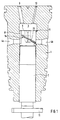
- reference numeral 1 means the pump cylinder Fuel injection pump for an internal combustion engine, in particular a diesel engine.
- a pump piston 2 is displaceably guided in the axial direction of the pump cylinder 1, which of a camshaft acting on a piston foot of the pump piston is cyclically driven.
- the camshaft and piston foot are not shown in FIG. 1.
- the Pump piston 2 is provided at its lower end with a piston vane 11, which in cooperation with, for example, a rack a twist around Piston axis over a predetermined angular range.
- the pump piston 2 delimits on its upper side a pressure chamber 3 which is in the pump cylinder 1 is provided. At the top of the pressure chamber 3, an inlet channel 10 and open Drain channel 9 for the fuel.
- Control bores 4a and 4b are provided laterally in the pump cylinder 1.
- a that the upper end of the pump piston 2 forming piston head 5 is on a circumference with a upper, pressure chamber side control edge 6 and lower, oblique control edges 7a, 7b provided, of which only one control edge 7a is visible in Fig. 1.
- the top control edge 6 and the lower control edge 7a together limit a connection of the Pressure chamber 3 with the underside of the lower, oblique control edge 7a, 7b producing Piston groove 8 is a control triangle, which by sweeping the control holes 4a, 4b Determines the start and end of fuel delivery for the injection pump.
- Fuel injection pump are formed two such control triangles, each cooperate with the control bores 4a and 4b.
- Fig. 1 and Fig. 2a) to c is in the range from the bottom Control edge 7a, 7b on the pump piston 2 a pilot valve groove 20a, 20b in the form of a the routing of the lower control edge 7a, 7b provided.
- the Pre-control groove 20a, 20b is formed by a formed in the interior of the pump piston 2 Flow connection with the piston head 5 and thus with the pressure chamber in Connection.
- the flow connection is through a in the center of the pump piston 2 running axial bore 23 and two for each pilot valve groove 7a, 7b provided radially extending bores 21a, 22a and 21b, 22b.
- the upper side of the axial bore 23 is expanded by a cone 24.
- the pilot control groove 20a, 20b sweeps when the pump piston moves upward 2 earlier during the delivery stroke of the injection pump, the respective control bore 4a, 4b than the lower, oblique control edge 7a, 7b, so that an earlier pressure relief of the Pressure chamber 3 via the bores 23 and 21a, 22a, 21b, 22b and the pilot valve grooves 20a, 20b in the sense of ending fuel delivery.
- the cross section of the through the axial bore 23 and the radial bores 21a, 22a, 21b, 22b formed flow connection is selected so that a substantial degradation of the pressure energy stored in the printing space 3 takes place, so that in the final Pressure relief of the pressure chamber 3 via the lower control edge 7a, 7b no cavitation no longer occurs, but on the other hand, there is still no cavitation in the pilot control groove 20a, 20b occurs.
- the pre-tax grooves 20a, 20b are against the one adjoining the lower control edge 7a, 7b High pressure area sealed by a distance S by spacing.
- the radial bores 21a, 22a and 21b, 22b each open near the ends of the Pre-tax grooves 20a, 20b in this.
- the radial Bores 21a, 22a and 21b, 22b angularly offset from one another and open each in pairs diametrically opposite each other in the axial bore 23. Die mutual position of the radial bores 21a, 22a and 21b, 22b is again in Fig. 3a) shown enlarged.
- the axial bore 23 has between the mouths of the radial bores 21a, 21b and 22a, 22b a reduction in the cross section.
- the cross sections of the axial bore 23 50 selected that the first cross section at the first radial bore 21a, 21b approximately is twice as large as the second cross section at the second radial bore 22a, 22b.
- This reduction in the flow limiting in the axial bore 23 Cross section should be achieved that the flow from the pressure chamber 3 to the Pre-control grooves 20a, 20b approximately equal to the first radial bore 21a, 21b and the second radial bore 22a, 22b distributed.
- the cross sections of the holes chosen so that the cross section of the axial bore 23 is smaller than the sum of the Cross sections of the radial bores 21a, 21b and 22a, 22b opening into these.
- Fig. 3c shows a further enlarged section along the line A-B in Fig. 2c) in Pre-tax groove 20b.
- the edges of the pre-control groove are on rounded their sole with a radius R, which on the one hand improves the Flow behavior within the pre-control groove 20a, 20b and the other Strength of the pump piston 2 in the area of the pre-control groove 20a, 20b and serves in particular the heavily loaded lower control edges 7a, 7b.
- the Strength is the measure of the distance S between the pre-control groove 20a, 20b and lower control edge 7a, 7b of importance.
- This dimension S is to be chosen so that on the one hand the beginning of the pre-control when the pre-control groove 20a, 20b arrives at the Control bore 4a, 4b in an appropriate relationship to the end of fuel delivery when the lower control edge 7a, 7b arrives at the control bore 4a, 4b and on the other hand, the occurrence of damage in this highly stressed area of the Pump piston 2 is reliably excluded.
Landscapes
- Engineering & Computer Science (AREA)
- Chemical & Material Sciences (AREA)
- Combustion & Propulsion (AREA)
- Mechanical Engineering (AREA)
- General Engineering & Computer Science (AREA)
- Fuel-Injection Apparatus (AREA)
Applications Claiming Priority (2)
| Application Number | Priority Date | Filing Date | Title |
|---|---|---|---|
| DE19831078A DE19831078A1 (de) | 1998-07-10 | 1998-07-10 | Kraftstoffeinspritzpumpe |
| DE19831078 | 1998-07-10 |
Publications (3)
| Publication Number | Publication Date |
|---|---|
| EP0971123A2 true EP0971123A2 (fr) | 2000-01-12 |
| EP0971123A3 EP0971123A3 (fr) | 2001-04-18 |
| EP0971123B1 EP0971123B1 (fr) | 2003-05-07 |
Family
ID=7873708
Family Applications (1)
| Application Number | Title | Priority Date | Filing Date |
|---|---|---|---|
| EP99113205A Expired - Lifetime EP0971123B1 (fr) | 1998-07-10 | 1999-07-08 | Pompe d'injection de carburant |
Country Status (3)
| Country | Link |
|---|---|
| EP (1) | EP0971123B1 (fr) |
| AT (1) | ATE239868T1 (fr) |
| DE (2) | DE19831078A1 (fr) |
Cited By (4)
| Publication number | Priority date | Publication date | Assignee | Title |
|---|---|---|---|---|
| WO2003054376A1 (fr) * | 2001-12-21 | 2003-07-03 | L'orange Gmbh | Injecteur pour moteurs a combustion interne |
| EP1598548A1 (fr) * | 2004-05-20 | 2005-11-23 | Magneti Marelli Powertrain S.p.A. | Méthode et système d'injection directe de carburant dans un moteur à combustion interne |
| EP1505294B1 (fr) * | 2003-08-07 | 2007-01-24 | Delphi Technologies, Inc. | Ensemble de pompe |
| EP2525076A4 (fr) * | 2010-01-15 | 2016-03-16 | Hyun Dai Heavy Ind Co Ltd | Système d'injection d'une pompe d'injection de carburant |
Citations (1)
| Publication number | Priority date | Publication date | Assignee | Title |
|---|---|---|---|---|
| DE4304084C2 (de) | 1993-02-11 | 1995-03-09 | Orange Gmbh | Einspritzpumpenelement mit schrägen Steuerkanten |
Family Cites Families (7)
| Publication number | Priority date | Publication date | Assignee | Title |
|---|---|---|---|---|
| FR2067883A5 (fr) * | 1969-11-20 | 1971-08-20 | Peugeot | |
| US4163634A (en) * | 1977-11-25 | 1979-08-07 | Caterpillar Tractor Co. | Fuel pump plunger |
| DE3347430A1 (de) * | 1983-12-29 | 1985-07-11 | Robert Bosch Gmbh, 7000 Stuttgart | Kraftstoffeinspritzpumpe fuer brennkraftmaschinen |
| ATE54723T1 (de) * | 1986-11-21 | 1990-08-15 | Bosch Robert | Pumpenelement einer brennstoffeinspritzpumpe fuer einspritzbrennkraftmaschinen. |
| DE3804843A1 (de) * | 1988-02-17 | 1989-08-31 | Bosch Gmbh Robert | Kraftstoffeinspritzpumpe fuer brennkraftmaschinen |
| DE4002557C2 (de) * | 1990-01-30 | 1996-02-01 | Orange Gmbh | Hochdruck-Kolbenpumpe |
| DE4006899A1 (de) * | 1990-03-06 | 1991-09-12 | Mak Maschinenbau Krupp | Verfahren und vorrichtung zur vermeidung einer kavitation an einem pumpenelement einer einspritzpumpe |
-
1998
- 1998-07-10 DE DE19831078A patent/DE19831078A1/de not_active Withdrawn
-
1999
- 1999-07-08 AT AT99113205T patent/ATE239868T1/de not_active IP Right Cessation
- 1999-07-08 DE DE59905415T patent/DE59905415D1/de not_active Expired - Fee Related
- 1999-07-08 EP EP99113205A patent/EP0971123B1/fr not_active Expired - Lifetime
Patent Citations (1)
| Publication number | Priority date | Publication date | Assignee | Title |
|---|---|---|---|---|
| DE4304084C2 (de) | 1993-02-11 | 1995-03-09 | Orange Gmbh | Einspritzpumpenelement mit schrägen Steuerkanten |
Cited By (6)
| Publication number | Priority date | Publication date | Assignee | Title |
|---|---|---|---|---|
| WO2003054376A1 (fr) * | 2001-12-21 | 2003-07-03 | L'orange Gmbh | Injecteur pour moteurs a combustion interne |
| US6991179B2 (en) | 2001-12-21 | 2006-01-31 | L'orange Gmbh | Injector for internal combustion engines |
| EP1505294B1 (fr) * | 2003-08-07 | 2007-01-24 | Delphi Technologies, Inc. | Ensemble de pompe |
| EP1598548A1 (fr) * | 2004-05-20 | 2005-11-23 | Magneti Marelli Powertrain S.p.A. | Méthode et système d'injection directe de carburant dans un moteur à combustion interne |
| US7198034B2 (en) | 2004-05-20 | 2007-04-03 | Magneti Marelli Powertrain Spa | Method and system for the direct injection of fuel into an internal combustion engine |
| EP2525076A4 (fr) * | 2010-01-15 | 2016-03-16 | Hyun Dai Heavy Ind Co Ltd | Système d'injection d'une pompe d'injection de carburant |
Also Published As
| Publication number | Publication date |
|---|---|
| EP0971123A3 (fr) | 2001-04-18 |
| ATE239868T1 (de) | 2003-05-15 |
| DE59905415D1 (de) | 2003-06-12 |
| DE19831078A1 (de) | 2000-01-13 |
| EP0971123B1 (fr) | 2003-05-07 |
Similar Documents
| Publication | Publication Date | Title |
|---|---|---|
| DE2045556C3 (de) | Vorrichtung zur Kraftstoffeinspritzung in die Zylinder einer mit Druckzündung arbeitenden Brennkraftmaschine | |
| DE2806788A1 (de) | Pumpe-duese fuer brennkraftmaschinen | |
| DE3926166A1 (de) | Kraftstoffeinspritzpumpe fuer dieselbrennkraftmaschinen | |
| CH628957A5 (de) | Kraftstoff-einspritzduese. | |
| DE2750929A1 (de) | Kraftstoff-einspritzduese fuer brennkraftmaschinen | |
| DE3809700C2 (fr) | ||
| EP0263304B1 (fr) | Pompe d'injection de carburant pour moteurs à combustion interne | |
| DE1947528C3 (de) | Kraftstoffeinspritzpumpe für Brennkraftmaschinen | |
| DE4437927C2 (de) | Magnetventilgesteuerte Kraftstoffeinspritzvorrichtung mit einer Einspritzdüse zur Kraftstoffeinspritzung in den Brennraum einer Dieselbrennkraftmaschine | |
| DE3804025C2 (fr) | ||
| DE4443860A1 (de) | Kraftstoffeinspritzpumpe für Brennkraftmaschinen | |
| DE10062959A1 (de) | Kraftstoffeinspritzventil für Brennkraftmaschinen | |
| EP0971123B1 (fr) | Pompe d'injection de carburant | |
| DE3801929C2 (de) | Kraftstoffeinspritzeinrichtung | |
| DE3102801C2 (fr) | ||
| WO1989010479A1 (fr) | Unite de cylindre et piston a haute pression | |
| DE2650368C2 (de) | Pumpenkolben für eine Kraftstoffeinspritzpumpe einer Brennkraftmaschine | |
| DE2532205C3 (de) | Brennstoffeinspritzpumpe für Dieselbrennkraftmaschinen | |
| DE2900874C2 (de) | Kraftstoffeinspritzpumpe für Brennkraftmaschinen | |
| EP0906506B1 (fr) | Pompe d'injection de carburant pour moteur a combustion interne | |
| EP0263807B1 (fr) | Partie de pompe à combustible pour moteur à injection | |
| DE3644150C2 (de) | Kraftstoffeinspritzpumpe für Brennkraftmaschinen | |
| DE3841322C2 (fr) | ||
| DE3630647A1 (de) | Kraftstoffeinspritzpumpe fuer brennkraftmaschinen | |
| DE4041503C2 (de) | Kraftstoffeinspritzpumpe für Brennkraftmaschinen |
Legal Events
| Date | Code | Title | Description |
|---|---|---|---|
| PUAI | Public reference made under article 153(3) epc to a published international application that has entered the european phase |
Free format text: ORIGINAL CODE: 0009012 |
|
| AK | Designated contracting states |
Kind code of ref document: A2 Designated state(s): AT CH DE GB IT LI |
|
| AX | Request for extension of the european patent |
Free format text: AL;LT;LV;MK;RO;SI |
|
| PUAL | Search report despatched |
Free format text: ORIGINAL CODE: 0009013 |
|
| AK | Designated contracting states |
Kind code of ref document: A3 Designated state(s): AT BE CH CY DE DK ES FI FR GB GR IE IT LI LU MC NL PT SE |
|
| AX | Request for extension of the european patent |
Free format text: AL;LT;LV;MK;RO;SI |
|
| RIC1 | Information provided on ipc code assigned before grant |
Free format text: 7F 02M 59/26 A, 7F 02M 55/00 B |
|
| 17P | Request for examination filed |
Effective date: 20010517 |
|
| AKX | Designation fees paid |
Free format text: AT CH DE GB IT LI |
|
| 17Q | First examination report despatched |
Effective date: 20020201 |
|
| GRAH | Despatch of communication of intention to grant a patent |
Free format text: ORIGINAL CODE: EPIDOS IGRA |
|
| GRAH | Despatch of communication of intention to grant a patent |
Free format text: ORIGINAL CODE: EPIDOS IGRA |
|
| GRAH | Despatch of communication of intention to grant a patent |
Free format text: ORIGINAL CODE: EPIDOS IGRA |
|
| GRAA | (expected) grant |
Free format text: ORIGINAL CODE: 0009210 |
|
| AK | Designated contracting states |
Designated state(s): AT CH DE GB IT LI |
|
| REG | Reference to a national code |
Ref country code: GB Ref legal event code: FG4D Free format text: NOT ENGLISH |
|
| REG | Reference to a national code |
Ref country code: CH Ref legal event code: EP |
|
| REG | Reference to a national code |
Ref country code: CH Ref legal event code: NV Representative=s name: ISLER & PEDRAZZINI AG |
|
| REF | Corresponds to: |
Ref document number: 59905415 Country of ref document: DE Date of ref document: 20030612 Kind code of ref document: P |
|
| GBT | Gb: translation of ep patent filed (gb section 77(6)(a)/1977) |
Effective date: 20030805 |
|
| PLBE | No opposition filed within time limit |
Free format text: ORIGINAL CODE: 0009261 |
|
| STAA | Information on the status of an ep patent application or granted ep patent |
Free format text: STATUS: NO OPPOSITION FILED WITHIN TIME LIMIT |
|
| 26N | No opposition filed |
Effective date: 20040210 |
|
| PGFP | Annual fee paid to national office [announced via postgrant information from national office to epo] |
Ref country code: DE Payment date: 20070719 Year of fee payment: 9 |
|
| REG | Reference to a national code |
Ref country code: CH Ref legal event code: PCAR Free format text: ISLER & PEDRAZZINI AG;POSTFACH 1772;8027 ZUERICH (CH) |
|
| PGFP | Annual fee paid to national office [announced via postgrant information from national office to epo] |
Ref country code: CH Payment date: 20070713 Year of fee payment: 9 Ref country code: AT Payment date: 20070716 Year of fee payment: 9 |
|
| PGFP | Annual fee paid to national office [announced via postgrant information from national office to epo] |
Ref country code: GB Payment date: 20070720 Year of fee payment: 9 |
|
| PGFP | Annual fee paid to national office [announced via postgrant information from national office to epo] |
Ref country code: IT Payment date: 20070725 Year of fee payment: 9 |
|
| REG | Reference to a national code |
Ref country code: CH Ref legal event code: PL |
|
| GBPC | Gb: european patent ceased through non-payment of renewal fee |
Effective date: 20080708 |
|
| PG25 | Lapsed in a contracting state [announced via postgrant information from national office to epo] |
Ref country code: DE Free format text: LAPSE BECAUSE OF NON-PAYMENT OF DUE FEES Effective date: 20090203 Ref country code: AT Free format text: LAPSE BECAUSE OF NON-PAYMENT OF DUE FEES Effective date: 20080708 |
|
| PG25 | Lapsed in a contracting state [announced via postgrant information from national office to epo] |
Ref country code: LI Free format text: LAPSE BECAUSE OF NON-PAYMENT OF DUE FEES Effective date: 20080731 Ref country code: GB Free format text: LAPSE BECAUSE OF NON-PAYMENT OF DUE FEES Effective date: 20080708 Ref country code: CH Free format text: LAPSE BECAUSE OF NON-PAYMENT OF DUE FEES Effective date: 20080731 |
|
| PG25 | Lapsed in a contracting state [announced via postgrant information from national office to epo] |
Ref country code: IT Free format text: LAPSE BECAUSE OF NON-PAYMENT OF DUE FEES Effective date: 20080708 |