EP0971191A2 - Process and apparatus for heating goods by a heated gas - Google Patents
Process and apparatus for heating goods by a heated gas Download PDFInfo
- Publication number
- EP0971191A2 EP0971191A2 EP99111709A EP99111709A EP0971191A2 EP 0971191 A2 EP0971191 A2 EP 0971191A2 EP 99111709 A EP99111709 A EP 99111709A EP 99111709 A EP99111709 A EP 99111709A EP 0971191 A2 EP0971191 A2 EP 0971191A2
- Authority
- EP
- European Patent Office
- Prior art keywords
- gas
- heated gas
- heated
- admixing
- cooler
- Prior art date
- Legal status (The legal status is an assumption and is not a legal conclusion. Google has not performed a legal analysis and makes no representation as to the accuracy of the status listed.)
- Granted
Links
Images


Classifications
-
- F—MECHANICAL ENGINEERING; LIGHTING; HEATING; WEAPONS; BLASTING
- F26—DRYING
- F26B—DRYING SOLID MATERIALS OR OBJECTS BY REMOVING LIQUID THEREFROM
- F26B23/00—Heating arrangements
- F26B23/02—Heating arrangements using combustion heating
Definitions
- the invention relates to a method for treating goods by means of a heated gas according to the preamble of claim 1 and a device according to the preamble of claim 8.
- a treatment of goods by means of heated gases takes place in different industrial machining processes, e.g. when drying wet or solvent-based products in drying plants, when curing paintwork or molded parts in the oven or when storing cold sensitive goods in Warehouses.
- a combination of storage and drying takes place in the large ones Drying rooms in which ceramic workpieces (e.g. refractory blocks for Construction of float glass pools, porcelain or high voltage insulators) often over Weeks to be dried.
- the heatable rooms mentioned as examples must be used to achieve a uniform temperature distribution targeted and even with the heated Gas flow. This is usually used accordingly dimensioned blowers.
- the air in the Circulation using moving air fans that move air out of the room, circulating air called, suction and elsewhere - after heating and cleaning if necessary - feed again.
- the high ones usually required Air volumes require the use of powerful fans, so that In order to save performance, the pressure losses in the air recirculation system are constructive must be minimized. This is done by using the flow cross sections for the Circulated air flows selected as large as possible and distributing units such as air baffles, Chokes etc. can be avoided.
- a dryer is from the brochure of H. Krantz Textiltechnik GmbH "K M 16" 4/94 for drying textile webs on several floors with a transport device for the web, with two fields, each with two superimposed Chambers and two circulating air devices per chamber with one circulating air fan, a pressure chamber that extends over several floors from the pressure chamber outgoing nozzle boxes on each floor above and below the Goods web are arranged side by side, a suction chamber and one in the Intake chamber protruding gas heating with a surface burner is known. By the burner gas emanating from such a surface burner becomes one Relatively uniform mixture of the burner gas with the recirculating air total height of the chambers achieved.
- the object of the invention is to provide a method for treating goods by means of a heated gas according to the preamble of claim 1 and a device to develop according to the preamble of claim 8, in which a uniform temperature distribution of the heated gas without high pressure losses is achieved in the flow path.
- the inventive method on the treatment of sheet or plate-shaped material in a recirculating air process in one Dryer can be used with several floors, so that in all floors of the dryer Drying air of the same temperature is supplied.
- heated gas is at least a point-shaped inlet is fed to a cooler gas and the thus formed heated gas is fed to the goods to be treated via a blower.
- the heated method is used according to the invention Gas in the area of the punctiform inlet mixed with an admixing gas, the admixing gas through a part of the flow behind the Blower located heated gas is formed.
- the mix in the area of punctiform inlet can be directly at or in front of the punctiform inlet take place, the point-shaped inlet as such being essentially retained, but it can also be arranged directly after the punctiform inlet Mixing device take place.
- the pure heated gas is not used in the method according to the invention supplied to the cooler gas, but a mixture that is as homogeneous as possible heated gas and admixing gas.
- the admixing gas consists of heated gas, it has a lower temperature than the heated gas.
- the mixture of heated Gas and admixing gas are therefore correspondingly cooler than the pure heated gas.
- the removal of the admixing gas from the one behind the fan warmed gas also has the advantages that, firstly, no separate gas must be provided and secondly the pressure of the - already existing - Blower for returning the admixing gas and mixing it with the heated gas is used. As a result, the existing systems and Procedure to be carried out change effort for the conversion to the method according to the invention minimized.
- the mixture of heated gas and admixing gas after punctiform inlet distributed in the vertical direction.
- Such a distribution is for that heated gas known from the prior art and advantageous when in Vertical gas flow is required for the treatment of the goods.
- a less hot mixture of heated gas and admixing gas and in addition a larger volume is present in the vertical distribution hardly any disturbing thermal effects and the result of Distribution is significantly more homogeneous.
- the cooler gas is in which the heated gas is let in, wholly or partly from circulating air.
- the gas is closed under circulating air understand which is supplied as heated gas to the goods to be treated was cooled and after it had acted on the goods and if necessary also with removing products.
- Such a procedure therefore works the recirculation principle, i.e. a cycle of the treatment used Gases, and therefore achieves a corresponding energy and gas savings.
- the heated gas is preferably hot air or the burner gas a gas or oil burner.
- gases are advantageous because of their Properties often used as heat sources in the prior art and are characterized by a naturally relatively high temperature. The one from this Problems resulting from high temperature are caused by the Method according to the invention effectively avoided.
- Claim 5 relates specifically to a method in which sheet or plate-shaped goods are dried on several levels using the air-circulation method, wherein, in at least one stage, heated gas as drying air is supplied to the good by a circulating air fan serving as a blower, via a pressure chamber and nozzle boxes connected to the pressure chamber and arranged on each floor above and possibly below the good, and wherein circulating air as cooler gas in one Suction chamber merged with heated gas and the drying air is supplied to the good again via the recirculation fan, the pressure chamber and the nozzle boxes.
- This known method is characterized according to the invention in that part of the drying air is returned as admixing gas from the pressure chamber into the suction chamber, mixed with the heated gas and this mixture is then fed to the circulating air.
- the mixture of heated gas and returned drying air has a larger volume and a lower temperature than the heated gas and is easier to mix with the circulating air to a drying air of homogeneous temperature.
- drying air is created, the temperature of which remains constant over the height of the suction chamber. A temperature gradient caused by heated gas rising due to the thermals is avoided.
- the goods transported through the dryer on floors are evenly dried.
- the heated gas to a Temperature from 160 to 220 ° C, the cooler gas to a temperature from 80 to 150 ° C and the heated gas at a temperature of about 2000 ° C. are preferably returned such an amount of admixing gas that the Temperature of the mixture of heated gas and admixing gas a temperature of 300 to 500 ° C, in particular from 350 to 450 ° C. With one Mixing temperature, the production of heated gas has become more homogeneous Temperature proved to be particularly simple.
- a proportion of 7 to 25%, in particular 10, attributed in accordance with claim 7 up to 20% of the heated gas as an admixing gas represents a mixture of heated Gas and cooler gas of homogeneous temperature safely.
- the invention also relates to a device for treating goods by means of a heated gas according to the preamble of claim 8, which a Has treatment room and a heating room.
- the treatment room can be of a very general form and e.g. as a separate chamber to the Connect the heating room or completely surround the heating room.
- the heating room has an inlet for a cooler gas, at least one punctiform inlet for the supply of heated gas into the cooler gas, one Heated gas outlet and a blower located at the outlet and is connected with its pressure side to the treatment room.
- the arrangement of the Blower at the exit of the heating room is done so that with the blower Gas can be pumped out of the heating room through the outlet.
- the fan can also form the outlet.
- the device is characterized in that the Heating room also a mixing device, which in the area of point-shaped inlet of the heated gas is arranged, and a Mixed gas supply line, which from the pressure side of the fan to the Mixer leads, contains.
- the arrangement of the mixing device can directly or before the punctiform inlet, the punctiform inlet as such remains essentially intact, but it can also be used directly after the point entry.
- the heated gas a cooler admixing gas can be added. This causes a drop in Temperature and an increase in volume one and the subsequent Mixing with the cooler gas in the heating room is significant steadier instead.
- the admixing gas can be via the mixed gas supply line from the pressure side of the Blower can be tapped. This has the advantage that the blower pressure is used, so no further structural measures or facilities are necessary to give the admixing gas the required pressure. In addition there is no need to provide any additional gas for the admixture as a existing gas is taken anyway.
- the heating room contains a distribution device which is arranged directly behind the point-shaped inlet for the heated gas and the extends in the horizontal and / or preferably in the vertical direction.
- the Extension preferably takes place approximately up to the limits of the Heating room so that the mixture is introduced as well as possible can be made from heated gas and admixing gas into the cooler gas.
- the punctiform in the device according to the invention Inlet designed as a burner, the flame tube protrudes into the heating room.
- This device is characterized in that the mixing device by a Outer tube that at least partially envelops the flame tube, and through inside this outer tube on the circumference distributed openings in the flame tube in this enveloped area is formed. This allows the admixing gas over the circumference of the flame tube flow evenly into the flame tube.
- Such Mixing device is structurally relatively simple, so that even existing burners can be retrofitted with this.
- the arrangement of the outer tube and the openings in the flame tube according to Claim 11 in the initial region of the burner gas in the flow direction Flame tube provides the longest possible mixing section between burner gas and Mixing gas safe.
- the mixed gas supply line is one in this device Connection line between his pressure chamber and the flame tube of his Brenner trained.
- the device is in accordance with a method claims 1 to 7 suitable.
- the device can be used as a dryer can be used to dry goods. From the pressure chamber you can use With the help of the connecting line, simply heated gas (drying air) to the burner lead back. Through the mouth of the connecting line in the flame tube, the Connection line can be arranged completely within the device.
- the starting point of the connecting line at the pressure chamber according to Providing claim 15 in the central region of the pressure chamber ensures in the pressure chamber a uniform flow of the drying air into the Nozzle boxes.
- the invention is initially generalized using a schematic illustration of a first example in Figure 1 explained.
- the invention is further illustrated schematically on the basis of one in FIGS. 2 to 4 illustrated second example of a dryer for a textile web explained.
- Figures 2 to 4 essentially show a side next to the web arranged suction chamber of a circulating air device of the dryer.
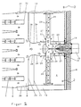
- Figure 2 is a Section through the central axis of a burner arranged in the suction chamber perpendicular to the transport levels of the web, d. H. parallel to the width of the Dryer.
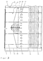
- Figure 3 is a view from the dryer wall in the direction of Goods web on a nozzle box of the air recirculation device and shows the location of one Filters and a cross flow fan.
- Figure 4 is a section parallel to the Transport levels of the web.
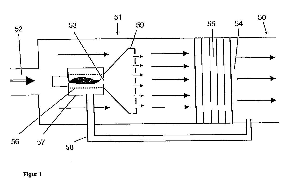
- Figure 1 shows a device for treating goods by means of heated gas with a treatment room 50 and a heating room 51.
- the Heating room 51 has an inlet 52 for a cooler gas, at least one point inlet 53 for supplying heated gas to the cooler gas and an outlet 54 for heated gas.
- the punctiform inlet 53 for heated gas can be on a wall of the heating space 50 or in its Inside.
- a heat source for example a burner
- the Outlet the punctiform inlet 53 for heated gas into the heating space 51 forms.
- the inlet 52 for the cooler gas is at the front in the flow direction End and outlet 54 for heated gas at the rear end of the Warming room 51, i.e. they lie one on top of the other at these two ends across from.
- the device also has a blower 55, which at the outlet 54 of the Heating room 51 is arranged and its suction point with the Heating room 51 and its pressure side with the treatment room 50 connected is.
- the fan 55 is a cross flow fan formed, which forms the outlet 54 of the heating chamber 51.
- the device has a mixing device 56, 57, which in the Area of the punctiform inlet 53 for the heated gas is arranged, and a mixed gas supply line 58, which from the pressure side of the blower 55 to the Mixing device 56, 57 leads.
- the one located inside the heating space 51 is Burner a gas burner with a flame tube 56, the open end of the Flame tube 56 forms the punctiform inlet 56.
- the flame tube 56 is of one additional outer tube 57 envelops and has openings within the envelope on.
- the mixing device is activated by the flame tube 56 provided with openings and the enveloping outer tube 57, the mixed gas supply line 58 to the Outer tube 57 is connected.
- the openings in the flame tube 56 are preferably arranged in the initial region of the flame tube 56.
- the mixing device is in front of the punctiform inlet 53 arranged.
- the scope of the invention also includes mixing devices which are arranged immediately behind the punctiform inlet 53.
- a distribution device 59 is connected to the punctiform inlet 53 extends vertically and / or horizontally into the heating space 51 and over the Extension has openings.
- the device described e.g. drying wet goods or hardening ceramic workpieces.
- the only indicated treatment room 50 be trained accordingly.
- it can be sent to the Heating space 51 can then be arranged behind it in the direction of flow or completely surround it.
- cooler gas through the inlet 52 Heating room 51 supplied.
- This gas can preferably be Circulating air from a cycle, act.
- the heating room 51 is the cooler Gas heated gas, namely fed burner gas.
- the gases leave the Heating space 51 at the outlet 54 via the fan 55 as a heated gas, the serves the treatment of the goods.
- the heated gas can be hot air or that Burner gas from a gas or oil burner.
- the burner gas is first fed through a mixing device 56, 57 a cooler admixing gas mixed in compared to the fuel gas.
- the Mixing gas is thereby via a mixed gas supply line 58 on the pressure side of the Blower 55 taken from the flow of the heated gas.
- the outer tube 57 and the openings in the flame tube 56 together act as a mixing device for the Burner gas and the admixing gas. This lowers the temperature of the mixture of burner gas and admixing gas compared to the burner gas, and the volume the mixture to be introduced into the cooler gas increases, so that the subsequent mixing with the cooler gas takes place homogeneously.
- the mixture of burner gas and admixing gas leaves via a point Inlet 53 the mixing device 56, 57 and is by means of the distribution device 59th evenly introduced into the flow of the cooler gas.
- the dryer has a cuboid housing a field, as well as a multi-day stenter frame with a tension chain, Guide rails and deflection wheels trained transport device.
- the field of this dryer is in two superimposed chambers 2, 3 divided.
- the lower chamber 2 extends over four floors, i. H. About four Transport levels of the web 1, and the upper chamber 3 over two more, in the drawing, not shown, transport levels of the web 1.
- each of the chambers 2, 3 there are two circulating air devices, each with its own Intake side connected to a suction chamber 4 recirculation fan in Longitudinal direction of the dryer, d. H. in or against the direction of transport of the web 1, arranged one behind the other.
- the suction chambers 4 with the circulating air fans are alternately on the sides of the dryer next to the web 1, d. H. Next the edges of the superimposed sections of the web 1, arranged.
- Exhaust air space 5 is formed between the web 1 and a housing wall 6.
- the exhaust air spaces 5 each open into the suction chamber 4 of the filter 7 neighboring air recirculation device.
- a recirculation device in addition to the recirculation fan and filter 7, one connected to the pressure side of the air circulation fan, between Suction chamber 4 and web 1 arranged as a pressure box 8 formed Pressure chamber and nozzle boxes 9 and one arranged in the suction chamber 4 Heating device with a burner 10.
- the nozzle boxes 9 are next to each other on each floor above and below the web 1 are arranged and extend over the maximum width of the web 1.
- the nozzle boxes 9 of a circulating air device and the nozzle boxes 9 of the two Adjacent circulating air devices closely follow in the longitudinal direction of the dryer on top of each other, so that the sections of the web 1 except for spaces between the nozzle boxes 9 completely from the nozzle boxes 9 above and below are covered.
- the circulating air fans are cross-flow fans 11 formed and extend over both chambers 2, 3.
- the suction chamber 4 is formed by a housing base 12 and a chamber 2 and 3 separating chamber bottom 13 and through the housing wall 6, the filter 7, a chamber wall 14, a baffle 15, the suction area of the Cross-flow fan 11 separates from the pressure area and the cross-flow fan 11 limited.
- the chamber wall 14 extends from perpendicular to the housing wall 6 arranged filter 7 first parallel to the housing wall 6 and then at an angle to the housing wall 6, in front of which the cross-flow fan 11 is arranged, to. It abuts the baffle plate 15. Near the filter 7, the chamber wall 14 an exhaust air duct 17.
- the burner 10 is approximately at half the height of the chamber 2 in the area of Suction chamber 4 installed in the insulated housing wall 6. Inside the Intake chamber 4, burner 10 has one attached to housing wall 6 Flame tube 18 on. Before the insulation of the housing wall 6 is in the area of Attachment of the flame tube 18 an insulating plate 19 is provided.
- the flame tube 18 has three sections 20, 21 and 22. In the area of the Housing wall 6 abutting section 20, the length of a quarter to one Corresponds to one third of the length of the flame tube 18, the flame tube 18 is perforated.
- the perforation is separated by a few mm, for example 2 mm, arranged circular openings with a diameter of 5 to 20 mm, for example of 10 mm.
- second section 21 of the flame tube 18 is an in Starting position horizontal, with one behind it in the direction of flow Axis 23 arranged gas distribution flap 24.
- gas distribution flap 24 In Flow direction subsequent to the gas distribution flap 24 are in the Flame tube 18 each have an up and down curved baffle 25, each in a distributor pipe 26, namely in its first section 27, opens out.
- the Manifolds 26 extend upward from the flame tube 18 and below.
- At the first rectangular section 27 there is a constant cross section in each case a second section 28 flanged.
- the second section 28 of each The distributor tube 26 tapers, as can be seen in FIG. 3, parallel to the longitudinal wall of the Dryer on the side facing away from the crossflow fan 11 or downward.
- the second section 28 has one over almost its entire length opening 29 directed toward cross-flow fan 11.
- the length of the second Section 21 of the flame tube 18 is approximately half the length of the Flame tube 18.
- the third section 22 of the flame tube 18 is on the opening 29 opposite side slightly tapered inwards.
- the pressure box 8 has a bottom wall 30, a top wall 31, one for Material web 1 directed, vertical side wall 32 with openings for the Nozzle boxes 9 and a side wall 33 running obliquely to the housing wall 6 on.
- the sloping part of the chamber wall 14 and the side wall 33 of the pressure box 8 run approximately parallel.
- a mixed gas feed line designed as a connecting line 34, leads from the pressure box 8 through the chamber wall 14 to the burner 10.
- the connecting line 34 has two connecting sections 35, 36 and a starting from the pressure box 8 Outer tube 37 on.
- the outer tube 37 envelops the flame tube 18 and is together attached to the housing wall 6 with the flame tube 18.
- the diameter of the Round outer tube 37 is about 1.1 to 1.5 times, for example 1.3 times the diameter of the flame tube 18.
- the connecting portions 36 and 35 of the outer tube 37 of the Connecting line 34 are, as can be seen in Figure 4, obliquely to the longitudinal direction of the Dryer, arranged and open at an almost right angle in the mine sloping side wall 33 in the print box 8.
- the Connecting section 36 leads from the outer tube 37 to an opening in the Chamber wall 14 and the following connecting section 35 of the connecting line 34 from the opening 28 of the chamber wall to the pressure box 8. Both Connecting sections 35, 36 are attached to the chamber wall 14.
- the lower chamber 2 are corresponding Circulating air devices arranged.
- An inventive Device can be used as a dryer for drying material webs from other Materials such as paper, plastic, metal or as a dryer for drying Building material parts, for example tarpaulin.
- the transport device can as a meandering transport device or parallel in several floors Transport device be formed.
- the textile web 1 is transported in several by means of the transport device Floors, in this example run from bottom to top through the dryer.
- the of the Goods web 1, circulating air (called exhaust air in the priority application) flows through an exhaust air space 5 and a filter 7 into the suction chamber 4, from which a Part is withdrawn via the exhaust air duct 17 as exhaust air and in which the rest Recirculated air is heated to drying air using hot burner gas.
- the cross-flow fan 11 sucks the drying air out of the suction chamber 4 and guides them to the web 1 over the print box 8 and the nozzle boxes 9 again.
- a portion of 7 to 25%, especially 10 to 20% of the drying air is over the connecting line 34 is withdrawn from the pressure box 9 and under pressure in the suction chamber 4 is returned to the flame tube 18 of the burner.
- the Drying air flows out of the outer tube 37 of the connecting line 34 through the Perforation of the flame tube 18 distributed over the circumference of the flame tube in the Flame tube 18 in which the burner gas is mixed with the drying air.
- This Mixture emerges from the openings 29 of the distributor pipes 26 over almost the entire Height of the chambers 2 and corresponding to the chamber 3 and is in one large area mixed with the recirculated air.
- the amount of returned drying air is adjusted so that the Mixture of burner gas and drying air at a temperature of 300 to 500 ° C, in particular from 350 to 450 ° C.
- a temperature of the circulating air of 150 ° C and a temperature of the burner gas of about 2000 ° C Return a proportion of approximately 20% of the drying air to a temperature of Mixture of burner gas and drying air set at 400 ° C.
Landscapes
- Engineering & Computer Science (AREA)
- Chemical & Material Sciences (AREA)
- Combustion & Propulsion (AREA)
- Life Sciences & Earth Sciences (AREA)
- Sustainable Development (AREA)
- Mechanical Engineering (AREA)
- General Engineering & Computer Science (AREA)
- Drying Of Solid Materials (AREA)
Abstract
Bei bekannten Vorrichtungen, z.B. Trocknern mit Punktbrennern tritt das Problem auf, daß erhitztes Gas, d.h. Brennergas, sich unvollständig mit zu erwärmenden, kühleren Gas mischt, was zu einer ungleichmäßigen Temperatur des erwärmten Gases, d.h. der Trocknungsluft, führt Es soll ein Verfahren und eine entsprechende Vorrichtung entwickelt werden, bei dem Trocknungsluft homogener Temperatur erzeugt wird.In known devices, e.g. This happens in dryers with point burners Problem that heated gas, i.e. Burner gas, incomplete with too warming, cooler gas mixes, resulting in an uneven Temperature of the heated gas, i.e. the drying air, it should introduce Methods and a corresponding device are developed in which Drying air of homogeneous temperature is generated.
Dies wird erreicht, indem ein Teil der Trocknungsluft als Zumischgas zurückgeführt und mit dem Brennergas gemischt wird. Die Mischung aus Brennergas und Trocknungsluft läßt sich leichter mit dem kühleren Gas zu Trocknungsluft homogener Temperatur mischen als reines, heißes Brennergas.This is achieved by using part of the drying air as an admixing gas returned and mixed with the burner gas. The mixture of Burner gas and drying air are easier to use with the cooler gas Mix drying air at a homogeneous temperature than pure, hot Burner gas.
Trockner
Description
Die Erfindung betrifft ein Verfahren zum Behandeln von Gütern mittels eines
erwärmten Gases gemäß dem Oberbegriff des Anspruchs 1 und eine Vorrichtung
gemäß dem Oberbegriff des Anspruchs 8.The invention relates to a method for treating goods by means of a
heated gas according to the preamble of
Eine Behandlung von Gütern mittels erwärmter Gase findet in verschiedenen industriellen Bearbeitungsprozessen statt, z.B. beim Trocknen nasser oder lösemittelhaltiger Produkte in Trockenanlagen, beim Aushärten von Lackierungen oder Formteilen in Ofen oder beim Lagern von kälteempfindlichen Gütern in Lagerhallen. Eine Kombination von Lagerung und Trocknung erfolgt in den großen Trocknungsräumen, in denen keramische Werkstücke (z.B. Feuerfestblöcke zum Bau von Floatglasbecken, Porzellan oder Hochspannungsisolatoren) oft über Wochen getrocknet werden.A treatment of goods by means of heated gases takes place in different industrial machining processes, e.g. when drying wet or solvent-based products in drying plants, when curing paintwork or molded parts in the oven or when storing cold sensitive goods in Warehouses. A combination of storage and drying takes place in the large ones Drying rooms in which ceramic workpieces (e.g. refractory blocks for Construction of float glass pools, porcelain or high voltage insulators) often over Weeks to be dried.
Die beispielhaft genannten beheizbaren Räume müssen zur Erzielung einer gleichmäßigen Temperaturverteilung gezielt und gleichmäßig mit dem erwärmten Gas durchströmt werden. Dazu verwendet man in der Regel entsprechend dimensionierte Gebläse. Vorzugsweise wird aus ökonomischen Gründen die Luft im Kreislaufverfahren über Umluftventilatoren bewegt, die aus dem Raum Luft, Umluft genannt, absaugen und an anderer Stelle - nach einer Erwärmung und gegebenenfalls Reinigung - wieder zuführen. Die in der Regel benötigten hohen Luftmengen erfordern dabei den Einsatz leistungsstarker Ventilatoren, so daß zum Zwecke der Leistungsersparnis die Druckverluste im Umluftsystem konstruktiv minimiert werden müssen. Dies geschieht, indem die Strömungsquerschnitte für die Umluftströme möglichst groß gewählt und verteilende Einheiten wie Luftleitbleche, Drosseln usw. vermieden werden. The heatable rooms mentioned as examples must be used to achieve a uniform temperature distribution targeted and even with the heated Gas flow. This is usually used accordingly dimensioned blowers. For economic reasons, the air in the Circulation using moving air fans that move air out of the room, circulating air called, suction and elsewhere - after heating and cleaning if necessary - feed again. The high ones usually required Air volumes require the use of powerful fans, so that In order to save performance, the pressure losses in the air recirculation system are constructive must be minimized. This is done by using the flow cross sections for the Circulated air flows selected as large as possible and distributing units such as air baffles, Chokes etc. can be avoided.
Die zur Erzielung bzw. Erhaltung der gewünschten Umlufttemperaturen erforderlichen Energiemengen werden in der Regel von Wärmequellen geliefert, die räumlich nicht den gesamten Umluftstrom erfassen. Bei Heizkörpern hätte man zwar die Möglichkeit, die Heizkörperfläche dem Umluftquerschnitt anzupassen, dies geht jedoch nur solange, wie dadurch die Druckverluste nicht zu stark ansteigen. Bei dem häufig anzutreffenden Einsatz von Gasbrennern oder bei der Heißlufteinblasung ist der Energieeintrag dagegen praktisch punktförmig. Hierdurch kommt es zur Bildung von Heißluftsträhnen, die nur sehr schwer und nur unter Inkaufnahme von Druckverlusten durch entsprechende Verteilervorrichtungen beseitigt werden können. Der punktförmige Energieeintrag bringt außerdem mit sich, daß die Temperatur am Ort der Energiezufuhr sehr hoch ist, bei Gasbrennern typischerweise um 2000 bis 3000°C (Flammtemperatur). Dies führt in der Regel zu ausgeprägten Thermikeffekten: Die Heißluft steigt im relativ kühlen Umluftstrom mit Geschwindigkeiten nach oben, die z.T. in der Größenordnung der Umluftgeschwindigkeit liegen. Besonders bei vertikal ausgedehnten Anlagen kommt es dadurch leicht zu Temperaturkonzentrationen im oberen Bereich, d.h. unter der Decke der Trockenanlage.To achieve or maintain the desired ambient air temperatures required amounts of energy are usually supplied by heat sources that do not spatially record the entire circulating air flow. One would have with radiators the possibility of adapting the radiator surface to the circulating air cross-section is possible however only as long as the pressure losses do not increase too much. In which frequent use of gas burners or in hot air injection in contrast, the energy input is practically punctiform. This leads to education of hot air strands that are very difficult and only at the expense of Pressure losses can be eliminated by appropriate distribution devices can. The punctiform energy input also means that the Temperature at the place of energy supply is very high in gas burners typically around 2000 to 3000 ° C (flame temperature). This usually leads to pronounced thermal effects: the hot air rises in the relatively cool circulating air flow Speeds up, which in some cases in the order of the circulating air speed lie. This is particularly the case with vertically extended systems this easily leads to temperature concentrations in the upper range, i.e. under the Ceiling of the drying plant.
Eine Verbesserung der Energieverteilung kann hier durch Ventilatoren erreicht werden, die den Luftstrom vermischen, indem sie ihn durch einen relativ geringen Querschnitt fördern und durch Umlenkung am Laufrad mischen. Dies hat allerdings den Nachteil, daß auf der Druckseite des Ventilators Maßnahmen getroffen werden müssen, um die Geschwindigkeitsverteilung der Umluft zu vergleichmäßigen. Zudem ist der Einsatz derartiger mischender Ventilatoren aus den oben genannten Gründen relativ energieintensiv. Setzt man dagegen Umluftventilatoren ein, die großflächig arbeiten und damit kaum Mischwirkung haben, so spart man den Aufwand der Geschwindigkeitsverteilung, benötigt dagegen aber Maßnahmen zur Temperaturverteilung.Fans can improve the energy distribution here that mix the air flow by separating it by a relatively small amount Promote cross section and mix by deflecting the impeller. However, this has the disadvantage that measures are taken on the pressure side of the fan need to even out the speed distribution of the circulating air. In addition, the use of such mixing fans from the above Relatively energy-intensive reasons. However, if you use recirculation fans, the Working over a large area and thus hardly having any mixing effect, this saves you Effort of speed distribution, however, requires measures to Temperature distribution.
Die obigen allgemeinen Ausführungen werden im folgenden an dem speziellen und wirtschaftlichen bedeutungsvollen Beispiel des Trocknens von Textilbahnen näher erläutert. The above general explanations are based on the special and economic meaningful example of drying textile webs closer explained.
Aus dem Prospekt der H. Krantz Textiltechnik GmbH "K M 16" 4/94 ist ein Trockner zum Trocknen von Textilbahnen in mehreren Etagen mit einer Transportvorrichtung für die Warenbahn, mit zwei Feldern, mit jeweils zwei übereinander angeordneten Kammern und zwei Umluftvorrichtungen pro Kammer mit einem Umluftventilator, einer Druckkammer, die sich über mehrere Etagen erstreckt, von der Druckkammer ausgehende Düsenkästen, die in jeder Etage oberhalb und unterhalb der Warenbahn nebeneinander angeordnet sind, einer Ansaugkammer und einer in die Ansaugkammer ragende Gasheizung mit einem Flächenbrenner bekannt. Durch das von einem solchen Flächenbrenner ausgehende Brennergas wird eine verhältnismäßig gleichmäßige Mischung des Brennergases mit der Umluft über die gesamte Höhe der Kammern erzielt.A dryer is from the brochure of H. Krantz Textiltechnik GmbH "K M 16" 4/94 for drying textile webs on several floors with a transport device for the web, with two fields, each with two superimposed Chambers and two circulating air devices per chamber with one circulating air fan, a pressure chamber that extends over several floors from the pressure chamber outgoing nozzle boxes on each floor above and below the Goods web are arranged side by side, a suction chamber and one in the Intake chamber protruding gas heating with a surface burner is known. By the burner gas emanating from such a surface burner becomes one Relatively uniform mixture of the burner gas with the recirculating air total height of the chambers achieved.
Bei dem Einsatz eines, zum Beispiel mittig angeordneten, punktförmigen Ölbrenners sammelt sich aufgrund der Thermik das heiße Brennergas, dessen Temperatur etwa 2000°C beträgt, im oberen Bereich der Ansaugkammer. Dies führt, insbesondere bei der Verwendung eines sich über die gesamte Höhe der Kammer oder der beiden Kammern erstreckenden Querstromventilators, dazu, daß in den oberen Etagen wesentlich heißere Trocknungsluft zugeführt wird als in den unteren Etagen. Diese Gefahr besteht auch bei dem Einsatz eines Axialventilators. Bei Radialventilatoren können die extremen Temperaturunterschiede zwischen Umluft und Brennergas zu einer schwankenden Temperatur der Trocknungsluft führen.When using a point-type oil burner, for example in the center The hot burner gas, its temperature, collects due to the thermals Is 2000 ° C in the upper area of the suction chamber. This leads, in particular using one over the entire height of the chamber or both Chambers extending cross flow fan, to that in the upper floors much hotter drying air is supplied than in the lower floors. This There is also a risk when using an axial fan. For radial fans the extreme temperature differences between circulating air and burner gas can increase fluctuating temperature of the drying air.
Beim Einsatz von punktförmigen Ölbrennern ist es bereits bekannt, im Flammraum des Brenners ein die heißen Brennergase führendes Flammrohr mit Verteilerrohren anzuordnen. Die Verteilerrohre sind an dem Ende des Flammrohres angeordnet und weisen über ihre Länge Öffnungen zum Ausströmen des Brennergases auf. Flammrohr und Verteilerrohre können die Ansammlung von heißem Brennergas im oberen Bereich des Ansaugraumes nicht vollständig verhindern.When using punctiform oil burners, it is already known in the flame space of the burner is a flame tube carrying the hot burner gases with distributor tubes to arrange. The manifolds are located at the end of the flame tube and have openings along their length for the outflow of the burner gas. Flame tube and manifolds can accumulate hot burner gas in the Do not completely prevent the upper area of the intake chamber.
Aufgabe der Erfindung ist es, ein Verfahren zum Behandeln von Gütern mittels eines
erwärmten Gases gemäß dem Oberbegriff des Anspruchs 1 und eine Vorrichtung
gemäß dem Oberbegriff des Anspruchs 8 zu entwickeln, bei denen eine
gleichmäßige Temperaturverteilung des erwärmten Gases ohne hohe Druckverluste
im Strömungsweg erzielt wird. Insbesondere soll das erfindungsgemäße Verfahren
auf das Behandeln von bahn- oder plattenförmigem Gut im Umluftverfahren in einem
Trockner mit mehreren Etagen anwendbar sein, damit in allen Etagen des Trockners
Trocknungsluft gleicher Temperatur zugeführt wird.The object of the invention is to provide a method for treating goods by means of a
heated gas according to the preamble of
Die Aufgabe wird durch die kennzeichnenden Merkmale der Ansprüche 1 und 8
gelöst.The object is achieved by the characterizing features of
Gemäß Anspruch 1 wird wie beim Stand der Technik erhitztes Gas an mindestens
einem punktförmigen Einlaß einem kühleren Gas zugeführt und das so gebildete
erwärmte Gas über ein Gebläse zu den zu behandelnden Gütern geleitet.
Anders als bei den bekannten Verfahren wird erfindungsgemäß jedoch das erhitzte
Gas im Bereich des punktförmigen Einlasses mit einem Zumischgas gemischt,
wobei das Zumischgas durch einen Teil des sich in Strömungsrichtung hinter dem
Gebläse befindlichen erwärmten Gases gebildet wird. Die Mischung im Bereich des
punktförmigen Einlasses kann direkt bei oder vor dem punktförmigen Einlaß
erfolgen, wobei der punktförmige Einlaß als solcher im wesentlichen erhalten bleibt,
sie kann aber auch in einer direkt nach dem punktförmigen Einlaß angeordneten
Mischeinrichtung erfolgen.According to
Bei dem erfindungsgemäßen Verfahren wird demnach nicht das reine erhitzte Gas dem kühleren Gas zugeführt, sondern eine möglichst homogene Mischung aus erhitztem Gas und Zumischgas. Da das Zumischgas aus erwärmtem Gas besteht, hat es eine niedrigere Temperatur als das erhitzte Gas. Die Mischung aus erhitztem Gas und Zumischgas ist daher entsprechend kühler als das reine erhitzte Gas. Hierdurch werden die oben hinsichtlich des Standes der Technik geschilderten Nachteile bei der punktförmigen Zufuhr zu dem kühleren Gas vermieden. Es treten also keine Heißluftsträhnen oder Thermikeffekte auf und die Temperaturverteilung ist homogen. Während sich im Stand der Technik bei der Zusammenführung von erhitztem Gas und kühlerem Gas ein heterogenes Gemenge - statt einer homogenen Mischung - herausbildet, entsteht bei der Zusammenführung der Mischung aus erhitztem Gas und Zumischgas mit kühlerem Gas ein homogenes Gasgemisch mit einer entsprechend homogenen Temperaturverteilung.Accordingly, the pure heated gas is not used in the method according to the invention supplied to the cooler gas, but a mixture that is as homogeneous as possible heated gas and admixing gas. Since the admixing gas consists of heated gas, it has a lower temperature than the heated gas. The mixture of heated Gas and admixing gas are therefore correspondingly cooler than the pure heated gas. As a result, those described above with regard to the prior art Disadvantages in the point supply to the cooler gas avoided. Kick it so no hot air streaks or thermal effects and the temperature distribution is homogeneous. While in the prior art when merging heated gas and cooler gas a heterogeneous mixture - instead of one homogeneous mixture - forms, arises when the Mixture of heated gas and admixing gas with cooler gas a homogeneous Gas mixture with a correspondingly homogeneous temperature distribution.
Dieser vorteilhafte Effekt entsteht, wie erwähnt, weil das Zumischgas kühler ist als das erhitzte Gas, es dessen Temperatur herabsetzt und somit die Effekte durch extreme Temperaturunterschiede vermieden werden. Der vorteilhafte Effekt entsteht auch, weil das Volumen der in das kühlere Gas einzubringenden Gasmenge der Mischung größer ist als die Menge des erhitzten Gases. Diese Wirkung tritt unabhängig davon ein, aus welcher Quelle das Zumischgas stammt.This advantageous effect arises, as mentioned, because the admixing gas is cooler than the heated gas, it lowers its temperature and thus the effects extreme temperature differences can be avoided. The beneficial effect arises also because the volume of the amount of gas to be introduced into the cooler gas Mixture is greater than the amount of gas heated. This effect occurs regardless of which source the admixing gas comes from.
Die Entnahme des Zumischgases aus dem hinter dem Gebläse befindlichen erwärmten Gas hat darüber hinaus die Vorteile, daß erstens kein separates Gas bereitgestellt werden muß und daß zweitens der Druck des - ohnehin vorhandenen - Gebläses für die Rückführung des Zumischgases und dessen Mischung mit dem erhitzten Gas ausgenutzt wird. Hierdurch wird der an bestehenden Anlagen und Verfahren zu betreibende Änderungsaufwand für die Umrüstung auf das erfindungsgemäße Verfahren minimiert.The removal of the admixing gas from the one behind the fan warmed gas also has the advantages that, firstly, no separate gas must be provided and secondly the pressure of the - already existing - Blower for returning the admixing gas and mixing it with the heated gas is used. As a result, the existing systems and Procedure to be carried out change effort for the conversion to the method according to the invention minimized.
Nach Anspruch 2 wird die Mischung aus erhitztem Gas und Zumischgas nach dem
punktförmigen Einlaß in vertikaler Richtung verteilt. Eine solche Verteilung ist für das
erhitzte Gas aus dem Stand der Technik bekannt und vorteilhaft, wenn ein sich in
Vertikalrichtung erstreckender Gasstrom für die Behandlung der Güter benötigt wird.
Dadurch, daß erfindungsgemäß eine weniger heiße Mischung aus erhitztem Gas
und Zumischgas und zusätzlich ein größeres Volumen vorhanden ist, treten bei der
vertikalen Verteilung kaum noch störende Thermikeffekte auf und das Ergebnis der
Verteilung ist bedeutend homogener.According to
Gemäß Anspruch 3 besteht das kühlere Gas, in welches das erhitzte Gas
eingelassen wird, ganz oder teilweise aus Umluft. Dabei ist unter Umluft das Gas zu
verstehen, welches als erwärmtes Gas den zu behandelnden Gütern zugeführt
wurde und nach Einwirkung auf die Güter abgekühlt und gegebenenfalls mit zu
entfernenden Produkten beladen anfällt. Ein solches Verfahren arbeitet also nach
dem Umluftprinzip, d.h. einer Kreislaufführung des zur Behandlung eingesetzten
Gases, und erzielt daher eine entsprechende Energie- und Gasersparnis.According to
Das erhitzte Gas ist gemäß Anspruch 4 vorzugsweise Heißluft oder das Brennergas eines Gas- oder Ölbrenners. Derartige Gase werden aufgrund ihrer vorteilhaften Eigenschaften als Wärmequellen im Stand der Technik häufig eingesetzt und zeichnen sich durch eine naturgemäß relative hohe Temperatur aus. Die aus dieser hohen Temperatur resultierenden Probleme werden dabei durch das erfindungsgemäße Verfahren wirkungsvoll vermieden.The heated gas is preferably hot air or the burner gas a gas or oil burner. Such gases are advantageous because of their Properties often used as heat sources in the prior art and are characterized by a naturally relatively high temperature. The one from this Problems resulting from high temperature are caused by the Method according to the invention effectively avoided.
Anspruch 5 betrifft speziell ein Verfahren, bei dem bahn- oder plattenförmige Güter
in mehreren Etagen im Umluftverfahren getrocknet werden,
wobei ferner in mindestens einer Stufe erwärmtes Gas als Trocknungsluft durch
einen als Gebläse dienenden Umluftventilator über eine Druckkammer und an die
Druckkammer angeschlossene, in jeder Etage oberhalb und ggf. unterhalb des
Gutes angeordnete Düsenkästen dem Gut zugeführt wird, und wobei Umluft als
kühleres Gas in einer Ansaugkammer mit erhitztem Gas zusammengeführt und als
Trocknungsluft über den Umluftventilator, die Druckkammer und die Düsenkästen
dem Gut erneut zugeführt wird. Dieses bekannte Verfahren ist erfindungsgemäß
dadurch gekennzeichnet, daß ein Teil der Trocknungsluft als Zumischgas aus der
Druckkammer in die Ansaugkammer zurückgeführt, mit dem erhitzten Gas gemischt
und diese Mischung anschließend der Umluft zugeführt wird . Die unter Druck
zurückgeführte Trocknungsluft höherer Temperatur als die der Umluft führt bei
Mischung mit dem erhitzten Gas (z.B. einem heißen Brennergas) zu einer Mischung
homogener Temperatur. Die Mischung aus erhitztem Gas und zurückgeführter
Trocknungsluft hat ein größeres Volumen und eine niedrigere Temperatur als das
erhitzte Gas und läßt sich einfacher mit der Umluft zu einer Trocknungsluft
homogener Temperatur mischen. Insbesondere entsteht eine Trocknungsluft, deren
Temperatur über die Höhe der Ansaugkammer gleichbleibt. Ein Temperaturgefälle
durch aufgrund der Thermik aufsteigendes erhitztes Gas wird vermieden. Die in
Etagen durch den Trockner transportierten Güter werden gleichmäßig getrocknet. Claim 5 relates specifically to a method in which sheet or plate-shaped goods are dried on several levels using the air-circulation method,
wherein, in at least one stage, heated gas as drying air is supplied to the good by a circulating air fan serving as a blower, via a pressure chamber and nozzle boxes connected to the pressure chamber and arranged on each floor above and possibly below the good, and wherein circulating air as cooler gas in one Suction chamber merged with heated gas and the drying air is supplied to the good again via the recirculation fan, the pressure chamber and the nozzle boxes. This known method is characterized according to the invention in that part of the drying air is returned as admixing gas from the pressure chamber into the suction chamber, mixed with the heated gas and this mixture is then fed to the circulating air. The drying air returned under pressure at a higher temperature than that of the circulating air, when mixed with the heated gas (eg a hot burner gas), leads to a mixture of homogeneous temperature. The mixture of heated gas and returned drying air has a larger volume and a lower temperature than the heated gas and is easier to mix with the circulating air to a drying air of homogeneous temperature. In particular, drying air is created, the temperature of which remains constant over the height of the suction chamber. A temperature gradient caused by heated gas rising due to the thermals is avoided. The goods transported through the dryer on floors are evenly dried.
Gemäß Anspruch 6 wird bei einer Behandlung, bei der das erwärmte Gas auf eine
Temperatur von 160 bis 220 °C, das kühlere Gas auf eine Temperatur von 80 bis
150 °C und das erhitzte Gas auf eine Temperatur von etwa 2000 °C eingestellt
werden, bevorzugt eine solche Menge Zumischgas zurückgeführt, daß die
Temperatur der Mischung aus erhitztem Gas und Zumischgas eine Temperatur von
300 bis 500 °C, insbesondere von 350 bis 450 °C aufweist. Bei einer solchen
Mischungstemperatur hat sich die Herstellung von erwärmtem Gas homogener
Temperatur als besonders einfach erwiesen.According to
Ein gemäß Anspruch 7 zurückgeführter Anteil von 7 bis 25 %, insbesondere von 10
bis 20 %, des erwärmten Gases als Zumischgas stellt eine Mischung von erhitztem
Gas und kühlerem Gas homogener Temperatur sicher.A proportion of 7 to 25%, in particular 10, attributed in accordance with
Die Erfindung betrifft auch eine Vorrichtung zum Behandeln von Gütern mittels eines
erwärmten Gases gemäß dem Oberbegriff des Anspruchs 8, welche einen
Behandlungsraum und einen Erwärmungsraum aufweist. Der Behandlungsraum
kann dabei sehr allgemeiner Form sein und sich z.B. als separate Kammer an den
Erwärmungsraum anschließen oder auch den Erwärmungsraum komplett umgeben.
Der Erwärmungsraum besitzt einen Einlaß für ein kühleres Gas, mindestens einen
punktförmigen Einlaß für die Zuführung von erhitztem Gas in das kühlere Gas, einen
Auslaß für erwärmtes Gas und ein Gebläse, welches am Auslaß angeordnet ist und
mit seiner Druckseite mit dem Behandlungsraum verbunden ist. Die Anordnung des
Gebläses am Ausgang des Erwärmungsraumes erfolgt so, daß mit dem Gebläse
Gas aus dem Erwärmungsraum durch den Auslaß heraus gefördert werden kann.
Insbesondere kann das Gebläse auch den Auslaß bilden.The invention also relates to a device for treating goods by means of a
heated gas according to the preamble of
Die Vorrichtung ist erfindungsgemäß dadurch gekennzeichnet, daß der Erwärmungsraum außerdem eine Mischeinrichtung, welche im Bereich des punktförmigen Einlasses des erhitzten Gases angeordnet ist, sowie eine Mischgaszuleitung, welche von der Druckseite des Gebläses zu der Mischeinrichtung führt, enthält. Die Anordnung der Mischeinrichtung kann direkt bei oder vor dem punktförmigen Einlaß erfolgen, wobei der punktförmige Einlaß als solcher im wesentlichen erhalten bleibt, sie kann aber auch direkt nach dem punktförmigen Einlaß erfolgen. Über die Mischeinrichtung kann dem erhitzten Gas ein kühleres Zumischgas zugemischt werden. Dadurch tritt eine Senkung der Temperatur und eine Erhöhung des Volumens ein und die nachfolgende Vermengung mit dem kühleren Gas im Erwärmungsraum findet bedeutend gleichmäßiger statt.The device is characterized in that the Heating room also a mixing device, which in the area of point-shaped inlet of the heated gas is arranged, and a Mixed gas supply line, which from the pressure side of the fan to the Mixer leads, contains. The arrangement of the mixing device can directly or before the punctiform inlet, the punctiform inlet as such remains essentially intact, but it can also be used directly after the point entry. Via the mixing device, the heated gas a cooler admixing gas can be added. This causes a drop in Temperature and an increase in volume one and the subsequent Mixing with the cooler gas in the heating room is significant steadier instead.
Das Zumischgas kann dabei über die Mischgaszuleitung von der Druckseite des Gebläses abgegriffen werden. Das hat den Vorteil, daß der Gebläsedruck ausgenutzt wird, also keine weiteren baulichen Maßnahmen oder Einrichtungen notwendig sind, um dem Zumischgas den erforderlichen Druck zu geben. Zudem muß kein weiteres Gas extra für die Zumischung bereitgestellt werden, da ein ohnehin vorhandenes Gas genommen wird.The admixing gas can be via the mixed gas supply line from the pressure side of the Blower can be tapped. This has the advantage that the blower pressure is used, so no further structural measures or facilities are necessary to give the admixing gas the required pressure. In addition there is no need to provide any additional gas for the admixture as a existing gas is taken anyway.
Gemäß Anspruch 9 enthält der Erwärmungsraum eine Verteilvorrichtung, welche
direkt hinter dem punktförmigen Einlaß für das erhitzte Gas angeordnet ist und die
sich in horizontaler und/oder vorzugsweise in vertikaler Richtung erstreckt. Die
Erstreckung erfolgt dabei vorzugsweise in etwa bis zu den Grenzen des
Erwärmungsraumes, so daß eine möglichst gut verteilte Einleitung der Mischung
aus erhitztem Gas und Zumischgas in das kühlere Gas erfolgen kann.According to
Gemäß Anspruch 10 ist bei der erfindungsgemäßen Vorrichtung der punktförmige
Einlaß als Brenner ausgebildet, dessen Flammrohr in den Erwärmungsraum ragt.
Diese Vorrichtung ist dadurch gekennzeichnet, daß die Mischeinrichtung durch ein
Außenrohr, das das Flammrohr zumindest teilweise umhüllt, und durch innerhalb
dieses Außenrohres am Umfang verteilte Öffnungen im Flammrohr in diesem
umhüllten Bereich gebildet wird. Dadurch kann das Zumischgas über den Umfang
des Flammrohres verteilt gleichmäßig in das Flammrohr strömen. Eine solche
Mischeinrichtung ist konstruktiv relativ einfach, so daß sogar vorhandene Brennern
hiermit nachgerüstet werden können.According to
Die Anordnung des Außenrohres und der Öffnungen im Flammrohr gemäß
Anspruch 11 im in Strömungsrichtung des Brennergases Anfangsbereich des
Flammrohres stellt eine möglichst lange Mischstrecke zwischen Brennergas und
Zumischgas sicher.The arrangement of the outer tube and the openings in the flame tube according to
Eine Vorrichtung zum Behandeln von bahn- oder plattenförmigen Gut in mehreren
Etagen weist gemäß Anspruch 12 in bekannter Weise
Dabei umfaßt der sich über mehrere Etagen erstreckende Behandlungsraum für das Gut die Transportvorrichtung, die Druckkammer und die Düsenkästen. Erfindungsgemäß ist bei dieser Vorrichtung die Mischgaszuleitung als eine Verbindungsleitung zwischen seiner Druckkammer und dem Flammrohr seines Brenners ausgebildet. Die Vorrichtung ist zur Durchführung eines Verfahrens gemäß den Ansprüchen 1 bis 7 geeignet. Insbesondere kann die Vorrichtung als Trockner zum Trocknen von Gütern verwendet werden. Aus der Druckkammer läßt sich mit Hilfe der Verbindungsleitung einfach erwärmtes Gas (Trocknungsluft) zum Brenner zurückführen. Durch die Mündung der Verbindungsleitung im Flammrohr kann die Verbindungsleitung vollständig innerhalb der Vorrichtung angeordnet sein.The treatment room extends over several floors for the Good the transport device, the pressure chamber and the nozzle boxes. According to the invention, the mixed gas supply line is one in this device Connection line between his pressure chamber and the flame tube of his Brenner trained. The device is in accordance with a method claims 1 to 7 suitable. In particular, the device can be used as a dryer can be used to dry goods. From the pressure chamber you can use With the help of the connecting line, simply heated gas (drying air) to the burner lead back. Through the mouth of the connecting line in the flame tube, the Connection line can be arranged completely within the device.
Nach Anspruch 13 ist bei einer Vorrichtung der zuletzt genannten Art eine
Mischeinrichtung gemäß Anspruch 10 vorhanden, wobei das Außenrohr als Teil der
Verbindungsleitung ausgebildet ist. Diese teilweise Doppelfunktion der
Verbindungsleitung führt zu einer weiteren konstruktiven Vereinfachung und damit
zu einer Kostenersparnis.According to
Bei dem Einsatz von senkrecht zu den Transportebenen des Gutes verlaufenden,
sich über die gesamte Höhe der Druckkammer erstreckenden und mit Öffnungen
versehenen Verteilerrohren im Endbereich des Flammrohres umhüllt das Außenrohr
der Verbindungsleitung gemäß Anspruch 14 das Flammrohr vollständig und weist
Öffnungen für die durch das Außenrohr ragenden Verteilerrohre auf. Dies ist ein
konstruktiv einfacher Aufbau des Außenrohres.When using perpendicular to the transport planes of the goods,
extending over the entire height of the pressure chamber and with openings
provided manifolds in the end area of the flame tube envelops the outer tube
the connecting line according to
Die Ausgangsstelle der Verbindungsleitung an der Druckkammer gemäß
Anspruch 15 im mittleren Bereich der Druckkammer vorzusehen, gewährleistet in
der Druckkammer eine gleichmäßige Strömung der Trocknungsluft in die
Düsenkästen.The starting point of the connecting line at the pressure chamber according to
Providing
Die Erfindung wird zunächst allgemein anhand einer schematischen Abbildung eines ersten Beispiels in Figur 1 erläutert.The invention is initially generalized using a schematic illustration of a first example in Figure 1 explained.
Die Erfindung wird weiterhin anhand eines in den Figuren 2 bis 4 schematisch dargestellten zweiten Beispiels eines Trockners für eine textile Warenbahn erläutert.The invention is further illustrated schematically on the basis of one in FIGS. 2 to 4 illustrated second example of a dryer for a textile web explained.
Die Figuren 2 bis 4 zeigen im wesentlichen eine seitlich neben der Warenbahn angeordnete Ansaugkammer einer Umluftvorrichtung des Trockners. Figur 2 ist ein Schnitt durch die Mittelachse eines in der Ansaugkammer angeordneten Brenners senkrecht zu den Transportebenen der Warenbahn, d. h. parallel zur Breite des Trockners. Figur 3 ist ein Blick von der Trocknerlängswand in Richtung der Warenbahn auf einen Düsenkasten der Umluftvorrichtung und zeigt die Lage eines Filters und eines Querstromventilators. Figur 4 ist ein Schnitt parallel zu den Transportebenen der Warenbahn.Figures 2 to 4 essentially show a side next to the web arranged suction chamber of a circulating air device of the dryer. Figure 2 is a Section through the central axis of a burner arranged in the suction chamber perpendicular to the transport levels of the web, d. H. parallel to the width of the Dryer. Figure 3 is a view from the dryer wall in the direction of Goods web on a nozzle box of the air recirculation device and shows the location of one Filters and a cross flow fan. Figure 4 is a section parallel to the Transport levels of the web.
Figur 1 zeigt eine Vorrichtung zur Behandlung von Gütern mittels erwärmten Gases
mit einem Behandlungsraum 50 und einem Erwärmungsraum 51. Der
Erwärmungsraum 51 weist einen Einlaß 52 für ein kühleres Gas, mindestens einen
punktförmigen Einlaß 53 für die Zuführung von erhitztem Gas in das kühlere Gas
sowie einen Auslaß 54 für erwärmtes Gas auf. Der punktförmige Einlaß 53 für
erhitztes Gas kann sich an einer Wand des Erwärmungsraumes 50 oder in seinem
Inneren befinden. Im in Figur 1 dargestellten Beispiel befindet sich im Inneren des
Erwärmungsraumes 51 eine Wärmequelle, beispielsweise ein Brenner, dessen
Auslaß den punktförmigen Einlaß 53 für erhitztes Gas in den Erwärmungsraum 51
bildet.Figure 1 shows a device for treating goods by means of heated gas
with a
Der Einlaß 52 für das kühlere Gas befindet sich am in Strömungsrichtung vorderen
Ende und der Auslaß 54 für erwärmtes Gas am hinteren Ende des
Erwärmungsraumes 51, d.h., sie liegen einander an diesen beiden Enden
gegenüber.The
Die Vorrichtung weist weiterhin ein Gebläse 55 auf, das am Auslaß 54 des
Erwärmungsraumes 51 angeordnet ist und dessen Saugstelle mit dem
Erwärmungsraum 51 und dessen Druckseite mit dem Behandlungsraum 50
verbunden ist. In diesem Beispiel ist das Gebläse 55 als Querstromventilator
ausgebildet, der den Auslaß 54 des Erwärmungsraumes 51 bildet.The device also has a
Erfindungsgemäß weist die Vorrichtung eine Mischeinrichtung 56, 57, welche im
Bereich des punktförmigen Einlasses 53 für das erhitzte Gas angeordnet ist, und
eine Mischgaszuleitung 58 auf, welche von der Druckseite des Gebläses 55 zu der
Mischeinrichtung 56, 57 führt.According to the invention, the device has a
In diesem Beispiel ist der im Inneren des Erwärmungsraumes 51 angeordnete
Brenner ein Gasbrenner mit einem Flammrohr 56, wobei das offene Ende des
Flammrohrs 56 den punktförmigen Einlaß 56 bildet. Das Flammrohr 56 ist von einem
zusätzlichen Außenrohr 57 umhüllt und weist innerhalb der Umhüllung Öffnungen
auf. Die Mischeinrichtung wird durch das mit Öffnungen versehene Flammrohr 56
und das umhüllende Außenrohr 57 gebildet, wobei die Mischgaszuleitung 58 an das
Außenrohr 57 angeschlossen ist. Die Öffnungen im Flammrohr 56 sind
vorzugsweise im Anfangsbereich des Flammrohres 56 angeordnet. Die
Mischeinrichtung ist in diesem Beispiel vor dem punktförmigen Einlaß 53
angeordnet. Zum Rahmen der Erfindung gehören auch Mischeinrichtungen, die
unmittelbar hinter dem punktförmigen Einlaß 53 angeordnet sind. In this example, the one located inside the
An den punktförmigen Einlaß 53 ist eine Verteilvorrichtung 59 angeschlossen, die
sich vertikal und/oder horizontal in den Erwärmungsraum 51 erstreckt und über die
Erstreckung hinweg Öffnungen hat.A
Für die beschriebene Vorrichtung kommen verschiedene Anwendungen in Betracht,
z.B. das Trocknen nasser Güter oder das Aushärten von Werkstücken aus Keramik.
Je nach Art der Behandlung wird der nur angedeutete Behandlungsraum 50
entsprechend ausgebildet sein. Insbesondere kann er, wie dargestellt, an den
Erwärmungsraum 51 anschließend in Strömungsrichtung dahinter angeordnet sein
oder aber diesen komplett umgeben.Various applications are possible for the device described,
e.g. drying wet goods or hardening ceramic workpieces.
Depending on the type of treatment, the only indicated
Beim Betrieb dieser Vorrichtung wird kühleres Gas durch den Einlaß 52 dem
Erwärmungsraum 51 zugeführt. Bei diesem Gas kann es sich vorzugsweise um
Umluft aus einem Kreisprozeß, handeln. Im Erwärmungsraum 51 wird dem kühleren
Gas erhitztes Gas, nämlich Brennergas zugeführt. Die Gase verlassen den
Erwärmungsraum 51 am Auslaß 54 über das Gebläse 55 als erwärmtes Gas, das
der Behandlung der Güter dient. Das erhitzte Gas kann Heißluft oder das
Brennergas eines Gas- oder Ölbrenners sein.In the operation of this device, cooler gas through the
Erfindungsgemäß wird dem Brennergas zunächst über eine Mischeinrichtung 56, 57
ein, verglichen mit dem Brenngas , kühleres Zumischgas zugemischt. Das
Zumischgas wird dabei über eine Mischgaszuleitung 58 an der Druckseite des
Gebläses 55 dem Strom des erwärmten Gases entnommen. Das Außenrohr 57 und
die Öffnungen im Flammrohr 56 wirken zusammen als Mischeinrichtung für das
Brennergas und das Zumischgas. Dadurch senkt sich die Temperatur der Mischung
aus Brennergas und Zumischgas verglichen mit dem Brennergas, und das Volumen
der in das kühlere Gas einzubringenden Mischung nimmt zu, so daß die
nachfolgende Vermischung mit dem kühleren Gas homogen erfolgt.According to the invention, the burner gas is first fed through a mixing
Die Mischung aus Brennergas und Zumischgas verläßt über einen punktförmigen
Einlaß 53 die Mischeinrichtung 56, 57 und wird mittels der Verteilvorrichtung 59
gleichmäßig in den Strom des kühleren Gases eingeleitet. The mixture of burner gas and admixing gas leaves via a
Im zweiten Beispiel ist eine erfindungsgemäße Vorrichtung für bahn- oder
plattenförmiges Gut in mehreren Etagen mit einer Transportvorrichtung und mit
Umluftvorrichtungen als Mehretagenspannrahmentrockner für eine textile
Warenbahn 1 ausgebildet. Der Trockner weist ein quaderförmiges Gehäuse mit
einem Feld, sowie eine als mehretagiger Spannrahmen mit einer Spannkette,
Führungsschienen und Umlenkrädern ausgebildete Transportvorrichtung auf.In the second example, a device according to the invention for railway or
plate-shaped goods in several floors with a transport device and with
Circulating air devices as multi-day stenter dryer for a
Das Feld dieses Trockners ist in zwei übereinander angeordnete Kammern 2, 3
unterteilt. Die untere Kammer 2 erstreckt sich über vier Etagen, d. h. Über vier
Transportebenen der Warenbahn 1, und die obere Kammer 3 über zwei weitere, in
der Zeichnung nicht dargestellte Transportebenen der Warenbahn 1.The field of this dryer is in two
In jeder der Kammern 2, 3 sind zwei Umluftvorrichtungen mit je einem mit seiner
Saugseite an eine Ansaugkammer 4 angeschlossenen Umluftventilator in
Längsrichtung des Trockners, d. h. in bzw. gegen Transportrichtung der Warenbahn
1, hintereinander angeordnet. Die Ansaugkammern 4 mit den Umluftventilatoren
sind wechelseitig an den Seiten des Trockners neben der Warenbahn 1, d. h. neben
den Kanten der übereinander verlaufenden Abschnitte der Warenbahn 1,
angeordnet. Jeweils auf der gegenüberliegenden Seite der Warenbahn 1 ist ein
Abluftraum 5 zwischen der Warenbahn 1 und einer Gehäusewand 6 ausgebildet.
Die Ablufträume 5 münden jeweils über ein Filter 7 in die Ansaugkammer 4 der
benachbarten Umluftvorrichtung.In each of the
Eine Umluftvorrichtung weist zusätzlich zu dem Umluftventilator und dem Filter 7,
eine an die Druckseite des Umluftventilator angeschlossenen, zwischen
Ansaugkammer 4 und Warenbahn 1 angeordneten als Druckkasten 8 ausgebildete
Druckkammer und Düsenkästen 9 sowie eine in der Ansaugkammer 4 angeordnete
Heizeinrichtung mit einem Brenner 10 auf.A recirculation device, in addition to the recirculation fan and
Die, auch als Düsenfinger bezeichneten, Düsenkästen 9, gehen von den sich über
die gesamte Kammerhöhe erstreckenden Druckkästen 8 aus. Die Düsenkästen 9
sind in jeder Etage oberhalb und unterhalb der Warenbahn 1 nebeneinander
angeordnet sind und erstrecken sich über die maximale Breite der Warenbahn 1.
Die Düsenkästen 9 einer Umluftvorrichtung und die Düsenkästen 9 der beiden
benachbarten Umluftvorrichtungen folgen in Längsrichtung des Trockner dicht
aufeinander, so daß die Abschnitte der Warenbahn 1 bis auf Zwischenräume
zwischen den Düsenkästen 9 vollständig von den Düsenkästen 9 oben und unten
bedeckt sind.The
In diesem Beispiel sind die Umluftventilatoren als Querstromventilatoren 11
ausgebildet und erstrecken sich jeweils über beide Kammern 2, 3.In this example, the circulating air fans are
Die Erfindung wird im folgenden anhand der in der Zeichnung dargestellten
Ansaugkammer 4 der hinteren Umluftvorrichtung der unteren Kammer 2
beschrieben.The invention is described below with reference to the
Die Ansaugkammer 4 wird durch einen Gehäuseboden 12 und einen die Kammer 2
und 3 trennenden Kammerboden 13 sowie durch die Gehäusewand 6, den Filter 7,
eine Kammerwand 14, ein Leitblech 15, das den Saugbereich des
Querstromventilators 11 vom Druckbereich trennt und den Querstromventilator 11
begrenzt.The
Die Kammerwand 14 verläuft ausgehend vom senkrecht zur Gehäusewand 6
angeordneten Filter 7 zunächst parallel zur Gehäusewand 6 und anschließend
schräg auf die Gehäusewand 6, vor der der Querstromventilator 11 angeordnet ist,
zu. Sie stößt an das Leitblech 15. Nahe des Filters 7 weist die Kammerwand 14
einen Abluftkanal 17 auf.The
Der Brenner 10 ist etwa auf der Hälfte der Höhe der Kammer 2 im Bereich der
Ansaugkammer 4 in die isolierte Gehäusewand 6 eingebaut. Im Innern der
Ansaugkammer 4 weist der Brenner 10 ein an der Gehäusewand 6 befestigtes
Flammrohr 18 auf. Vor der Isolierung der Gehäusewand 6 ist im Bereich der
Befestigung des Flammrohres 18 eine Isolierplatte 19 vorgesehen. The
Das Flammrohr 18 weist drei Abschnitte 20, 21 und 22 auf. Im Bereich des an die
Gehäusewand 6 anstoßenden Abschnitts 20, dessen Länge einem Viertel bis einem
Drittel der Länge des Flammrohres 18 entspricht, ist das Flammrohr 18 perforiert.
Die Perforation wird durch im Abstand von einigen mm, zum Beispiel von 2 mm,
angeordneten, kreisrunden Öffnungen mit einem Durchmesse von 5 bis 20 mm,
zum Beispiel von 10 mm, gebildet.The
In zum Innern des Trockners anschließenden, d. h. im in Strömungsrichtung des
heißen Gases anschließenden, zweiten Abschnitt 21 des Flammrohres 18 ist eine in
Ausgangsstellung horizontale, durch eine in Strömungsrichtung dahinter liegende
Achse 23 winkelverstellbare Gasverteilungsklappe 24 angeordnet. In
Strömungsrichtung anschließend an die Gasverteilungsklappe 24 sind im
Flammrohr 18 je ein nach oben und unten gebogenes Leitblech 25, das jeweils in
ein Verteilerrohr 26, und zwar in dessen ersten Abschnitt 27, mündet. Die
Verteilerrohre 26 erstrecken sich ausgehend vom Flammrohr 18 nach oben und
unten. An den ersten rechteckigen Abschnitt 27 konstantem Querschnitt ist jeweils
ein zweiter Abschnitt 28 geflanscht. Der zweite Abschnitt 28 des jeweiligen
Verteilerrohres 26 verjüngt sich, wie in Figur 3 zu sehen, parallel zur Längswand des
Trockners auf der vom Querstromventilator 11 abgewandten Seite nach oben bzw.
nach unten. Der zweite Abschnitt 28 weist nahezu über seine gesamte Länge eine
zum Querstromventilator 11 gerichtete Öffnung 29 auf. Die Länge des zweiten
Abschnittes 21 des Flammrohres 18 beträgt etwa die Hälfte der Länge des
Flammrohres 18. Der dritte Abschnitt 22 des Flammrohres 18 ist auf der der Öffnung
29 gegenüberliegenden Seite leicht nach innen konisch abgeschrägt.In subsequent to the inside of the dryer, d. H. in the flow direction of the
hot gas adjoining,
Der Druckkasten 8 weist eine Bodenwand 30, eine Deckenwand 31, eine zur
Warenbahn 1 gerichtete, vertikale Seitenwand 32 mit Öffnungen für die
Düsenkästen 9 und eine schräg zur Gehäusewand 6 verlaufende Seitenwand 33
auf. Der schräge Teil der Kammerwand 14 und die Seitenwand 33 des Druckkasten
8 verlaufen annähernd parallel.The
Vom Druckkasten 8 führt eine als Verbindungsleitung 34 ausgebildete Mischgaszuleitung
durch die Kammerwand 14 zum Brenner 10. Die Verbindungsleitung 34
weist ausgehend vom Druckkasten 8 zwei Verbindungsabschnitte 35, 36 und ein
Außenrohr 37 auf. Das Außenrohr 37 umhüllt das Flammrohr 18 und ist zusammen
mit dem Flammrohr 18 an der Gehäusewand 6 befestigt. Der Durchmesser des
runden Außenrohres 37 beträgt etwa das 1,1 bis 1,5- Fache, zum Beispiel das 1,3-Fache
des Durchmessers des Flammrohres 18.A mixed gas feed line, designed as a connecting
Die an das Außenrohr 37 anschließenden Verbindungsabschnitte 36 und 35 der
Verbindungsleitung 34 sind, wie in Figur 4 zu sehen, schräg zur Längsrichtung des
Trockners, angeordnet und münden in annähernd rechtem Winkel in der Mine der
schräg verlaufenden Seitenwand 33 in den Druckkastens 8. Der
Verbindungsabschnitt 36 führt vom Außenrohr 37 bis zu einer Öffnung in der
Kammerwand 14 und der folgende Verbindungsabschnitt 35 der Verbindungsleitung
34 von der Öffnung 28 der Kammerwand zum Druckkasten 8. Beide
Verbindungsabschnitte 35, 36 sind an der Kammerwand 14 befestigt.The connecting
In der oberen Kammer 3 sind der unteren Kammer 2 entsprechende
Umluftvorrichtungen angeordnet.In the
Es können mehrere Felder hintereinander angeordnet sein. Eine erfindungsgemäße Vorrichtung kann als Trockner zum Trocknen von Warenbahnen aus weiteren Materialien, wie Papier, Kunststoff, Metall oder als Trockner zum Trocknen von Baustoffteilen, zum Beispiel Planen, ausgebildet sein. Die Transportvorrichtung kann als mäanderförmige Transportvorrichtung oder in mehrere Etagen parallele Transportvorrichtung ausgebildet sein.Several fields can be arranged one after the other. An inventive Device can be used as a dryer for drying material webs from other Materials such as paper, plastic, metal or as a dryer for drying Building material parts, for example tarpaulin. The transport device can as a meandering transport device or parallel in several floors Transport device be formed.
Im Betrieb wird die texile Warenbahn 1 mittels der Transportvorrichtung in mehreren
Etagen, in diesem Beispiel von unten nach oben durch den Trockner geführt.
Zunächst in der unteren Kammer 2 anschließend in der oberen Kammer 3 wird der
Warenbahn 1 jeweils durch die beiden hintereinander angeordneten
Umluftvorrichtungen mittels des Querstromventilators 11 durch den Druckkasten 8
und die Düsenkästen 9 Trocknungsluft zugeführt und dabei getrocknet. Die von der
Warenbahn 1 abströmende Umluft (in der Prioritätsanmeldung Abluft genannt)
strömt durch einen Abluftraum 5 und ein Filter 7 in die Ansaugkammer 4, aus der ein
Teil über den Abluftkanal 17 als Abluft abgezogen wird und in der die restliche
Umluft unter Verwendung von heißem Brennergas zu Trocknungsluft erwärmt wird.
Aus der Ansaugkammer 4 saugt der Querstromventilator 11 die Trocknungsluft ab
und führt sie der Warenbahn 1 über den Druckkasten 8 und die Düsenkästen 9
erneut zu.In operation, the
Ein Teil von 7 bis 25 %, insbesondere von 10 bis 20 % der Trocknungsluft wird über
die Verbindungsleitung 34 aus dem Druckkasten 9 abgezogen und unter Druck in
die Ansaugkammer 4 zum Flammrohr 18 des Brenners zurückgeführt. Die
Trocknungsluft strömt aus dem Außenrohr 37 der Verbindungsleitung 34 durch die
Perforierung des Flammrohres 18 über den Umfang des Flammrohres verteilt in das
Flammrohr 18, in dem das Brennergas mit der Trocknungsluft gemischt wird. Diese
Mischung tritt aus den Öffnungen 29 der Verteilerrohre 26 über nahezu die gesamte
Höhe der Kammern 2 und entsprechend der Kammer 3 aus und wird in einem
großen Bereich mit der Umluft gemischt.A portion of 7 to 25%, especially 10 to 20% of the drying air is over
the connecting
Bei einer Temperatur der Trocknungsluft von 160 bis 220 °C, einer Temperatur der Umluft von 80 bis 150 °C und einer Temperatur des Brennergases von etwa 2000°C, wird die Menge der zurückgeführten Trocknungsluft so eingestellt, daß die Mischung aus Brennergas und Trocknungsluft eine Temperatur von 300 bis 500 °C, insbesondere von 350 bis 450 °C aufweist.At a drying air temperature of 160 to 220 ° C, a temperature of Circulating air of 80 to 150 ° C and a temperature of the burner gas of about 2000 ° C, the amount of returned drying air is adjusted so that the Mixture of burner gas and drying air at a temperature of 300 to 500 ° C, in particular from 350 to 450 ° C.
Bei einer Temperatur der Trocknungsluft von 200 °C, einer Temperatur der Umluft von 150 °C und einer Temperatur des Brennergases von etwa 2000 °C wird durch Rückführung eines Anteils von etwa 20 % der Trocknungsluft eine Temperatur der Mischung aus Brennergas und Trocknungsluft von 400 °C eingestellt. At a temperature of the drying air of 200 ° C, a temperature of the circulating air of 150 ° C and a temperature of the burner gas of about 2000 ° C Return a proportion of approximately 20% of the drying air to a temperature of Mixture of burner gas and drying air set at 400 ° C.
- 11
- WarenbahnGoods web
- 22nd
- untere Kammerlower chamber
- 33rd
- obere Kammerupper chamber
- 44th
- AnsaugkammerSuction chamber
- 55
- AbluftraumExhaust air room
- 66
- GehäusewandHousing wall
- 77
- Filterfilter
- 88th
- DruckkastenPrint box
- 99
- DüsenkastenNozzle box
- 1010th
- Brennerburner
- 1111
- QuerstromventilatorCross flow fan
- 1212th
- GehäusebodenCase back
- 1313
- KammerbodenChamber floor
- 1414
- KammerwandChamber wall
- 1515
- LeitblechBaffle
- 1616
- --
- 1717th
- AbluftkanalExhaust duct
- 1818th
- FlammrohrFlame tube
- 1919th
- isolierplatteinsulating plate
- 2020th
- erster Abschnitt des Flammrohresfirst section of the flame tube
- 2121
- zweiter Abschnitt des Flammrohressecond section of the flame tube
- 2222
- dritter Abschnitt des Flammrohresthird section of the flame tube
- 2323
- Achseaxis
- 2424th
- GasverteilungsklappeGas distribution flap
- 2525th
- LeitblechBaffle
- 2626
- VerteilerrohrManifold
- 2727
- erster Abschnitt des Verteilerrohresfirst section of the manifold
- 2828
- zweiter Abschnitt des Verteilerrohressecond section of the manifold
- 2929
- Öffnung im VerteilerrohrOpening in the distributor pipe
- 3030th
- Bodenwand des DüsenkastensBottom wall of the nozzle box
- 3131
- Deckenwand des Düsenkastens Ceiling wall of the nozzle box
- 3232
- Seitenwand des DüsenkastensSide wall of the nozzle box
- 3333
- Seitenwand des DüsenkastensSide wall of the nozzle box
- 3434
- VerbindungsleitungConnecting line
- 3535
- Verbindungsabschnitt der VerbindungsleitungConnection section of the connecting line
- 3636
- Verbidnungsabschnitt der VerbindungsleitungConnection section of the connecting line
- 3737
- AußenrohrOuter tube
- 3838
- Öffnung in der KammerwandOpening in the chamber wall
- 5050
- BehandlungsraumTreatment room
- 5151
- ErwärmungsraumWarming room
- 5252
- EinlaßInlet
- 5353
- punktförmiger Einlaßpunctiform inlet
- 5454
- AuslaßOutlet
- 5555
- Gebläsefan
- 5656
- FlammrohrFlame tube
- 5757
- AußenrohrOuter tube
- 5858
- MischgaszuleitungMixed gas supply
- 5959
- VerteilvorrichtungDistribution device
Claims (15)
dadurch gekennzeichnet, daß
characterized in that
dadurch gekennzeichnet, daß die Mischung aus erhitztem Gas und Zumischgas nach dem punktförmigen Einlaß in vertikaler Richtung verteilt wird.Method according to claim 1,
characterized in that the mixture of heated gas and admixing gas is distributed vertically after the punctiform inlet.
dadurch gekennzeichnet, daß das kühlere Gas in Teilschritt a) ganz oder teilweise aus Umluft besteht.The method of claim 1 or 2,
characterized in that the cooler gas in partial step a) consists entirely or partially of circulating air.
wobei bahn- oder plattenförmige Güter in mehreren Etagen im Umluftverfahren getrocknet werden,
wobei ferner in mindestens einer Stufe erwärmtes Gas als Trocknungsluft durch einen als Gebläse dienenden Umluftventilator über eine Druckkammer und an die Druckkammer angeschlossene, in jeder Etage oberhalb und ggf. unterhalb des Gutes angeordnete Düsenkästen, dem Gut zugeführt wird,
und wobei Umluft als kühleres Gas in einer Ansaugkammer mit erhitztem Gas zusammengeführt und als Trocknungsluft über den Umluftventilator, die Druckkammer und die Düsenkästen dem Gut erneut zugeführt wird,
dadurch gekennzeichnet, daß
where sheet or plate-shaped goods are dried on several levels using the forced air method,
in which, in at least one stage, heated gas is supplied to the material as drying air by a circulating air fan serving as a blower, via a pressure chamber and nozzle boxes connected to the pressure chamber and arranged on each floor above and possibly below the material,
and wherein circulating air is brought together as a cooler gas in a suction chamber with heated gas and is fed back to the material as drying air via the circulating air fan, the pressure chamber and the nozzle boxes,
characterized in that
dadurch gekennzeichnet, daß
characterized in that
dadurch gekennzeichnet, daß der als Zumischgas zurückgeführte Teil des erwärmten Gases 7 bis 25 %, insbesondere 10 bis 20 % des gesamten erwärmten Gases beträgt.Method according to one of claims 1 to 6,
characterized in that the portion of the heated gas returned as admixing gas is 7 to 25%, in particular 10 to 20% of the total heated gas.
gekennzeichnet durch
characterized by
wobei der Erwärmungsraum (51) eine Verteilvorrichtung (26, 59) enthält, welche direkt hinter dem punktförmigen Einlaß (53) für das erhitzte Gas angeordnet ist und die sich vorzugsweise in vertikaler Richtung erstreckt.Device according to claim 8,
wherein the heating space (51) contains a distribution device (26, 59) which is arranged directly behind the point-shaped inlet (53) for the heated gas and which preferably extends in the vertical direction.
dadurch gekennzeichnet, daß die Mischeinrichtung durch ein Außenrohr (37, 57), das das Flammrohr (18, 56) zumindest teilweise umhüllt, und durch Öffnungen im Flammrohr (18, 56) in diesem umhüllten Bereich gebildet wird.Apparatus according to claim 8 or 9, wherein the punctiform inlet is designed as a burner, the flame tube of which projects into the heating space,
characterized in that the mixing device is formed by an outer tube (37, 57) which at least partially surrounds the flame tube (18, 56) and by openings in the flame tube (18, 56) in this covered area.
dadurch gekennzeichnet, daß die Öffnungen im Anfangsbereich des Flammrohres (18, 56) angeordnet sind.Apparatus according to claim 10,
characterized in that the openings are arranged in the initial region of the flame tube (18, 56).
dadurch gekennzeichnet, daß die Mischgaszuleitung als Verbindungsleitung (34) zwischen der Druckkammer (8) und der Mischeinrichtung ausgebildet ist.
characterized in that the mixed gas supply line is designed as a connecting line (34) between the pressure chamber (8) and the mixing device.
dadurch gekennzeichnet, daß das Außenrohr (37) als Teil der Verbindungsleitung (34) ausgebildet ist. Device according to claims 12 and 10,
characterized in that the outer tube (37) is formed as part of the connecting line (34).
dadurch gekennzeichnet, daß
characterized in that
dadurch gekennzeichnet, daß die Verbindungsleitung (34) vom mittleren Bereich des Druckkastens (8) ausgeht.Device according to one of claims 10 to 14, wherein the pressure chamber is formed by a pressure box arranged between the web and suction chamber,
characterized in that the connecting line (34) extends from the central region of the pressure box (8).
Applications Claiming Priority (4)
| Application Number | Priority Date | Filing Date | Title |
|---|---|---|---|
| DE19830664 | 1998-07-09 | ||
| DE19830664 | 1998-07-09 | ||
| DE19918102A DE19918102A1 (en) | 1998-07-09 | 1999-04-22 | Method and device for treating goods using a heated gas |
| DE19918102 | 1999-04-22 |
Publications (3)
| Publication Number | Publication Date |
|---|---|
| EP0971191A2 true EP0971191A2 (en) | 2000-01-12 |
| EP0971191A3 EP0971191A3 (en) | 2001-12-12 |
| EP0971191B1 EP0971191B1 (en) | 2005-02-09 |
Family
ID=26047291
Family Applications (1)
| Application Number | Title | Priority Date | Filing Date |
|---|---|---|---|
| EP99111709A Expired - Lifetime EP0971191B1 (en) | 1998-07-09 | 1999-06-17 | Process and apparatus for heating goods by a heated gas |
Country Status (4)
| Country | Link |
|---|---|
| EP (1) | EP0971191B1 (en) |
| KR (1) | KR100413867B1 (en) |
| AT (1) | ATE289051T1 (en) |
| PT (1) | PT971191E (en) |
Cited By (4)
| Publication number | Priority date | Publication date | Assignee | Title |
|---|---|---|---|---|
| CN1316221C (en) * | 2002-12-25 | 2007-05-16 | 乐金电子(天津)电器有限公司 | Air channel of drier |
| CN100343608C (en) * | 2002-12-25 | 2007-10-17 | 乐金电子(天津)电器有限公司 | Air supplying pipeline of drier |
| CN109225775A (en) * | 2018-11-06 | 2019-01-18 | 江苏大族展宇新能源科技有限公司 | The integrated baking oven of lithium battery coating machine |
| CN109539250A (en) * | 2018-10-30 | 2019-03-29 | 西安交通大学 | A kind of low NO and its built-in flue gas recycled introducing device |
Families Citing this family (2)
| Publication number | Priority date | Publication date | Assignee | Title |
|---|---|---|---|---|
| CN100526776C (en) * | 2004-05-13 | 2009-08-12 | Lg化学株式会社 | Treater oven for manufacturing prepreg |
| JP4237797B2 (en) * | 2004-05-13 | 2009-03-11 | エルジー・ケム・リミテッド | Treater oven for prepreg manufacturing |
Family Cites Families (11)
| Publication number | Priority date | Publication date | Assignee | Title |
|---|---|---|---|---|
| CH99095A (en) * | 1921-08-08 | 1923-05-01 | Scherhag Andreas | Method and device for obtaining warm air. |
| FR648100A (en) * | 1927-10-25 | 1928-12-05 | Krantz Shone H | Rower-dryer |
| US2541332A (en) * | 1947-11-05 | 1951-02-13 | Campbell Bowen | Portable drier |
| US3057611A (en) * | 1960-02-15 | 1962-10-09 | Bjerkan Engineering Service In | Burner-blower combination for grain dryers |
| FR1471324A (en) * | 1966-03-05 | 1967-03-03 | Heating apparatus associated with a drying installation usable for drying fruit, hops and similar products | |
| DE2164860A1 (en) * | 1971-12-27 | 1973-06-28 | Kroenert Max Maschf | THIN DRYER |
| DK462875A (en) * | 1974-10-25 | 1976-04-26 | Claas Maschf Gmbh Geb | DRYING DRUM FOR GRONHOST |
| US4147115A (en) * | 1977-09-14 | 1979-04-03 | Leppert Alfred M | Incinerator with gas generation |
| GB1583199A (en) * | 1977-12-01 | 1981-01-21 | Whiteley Ltd E Gordon | Cloth drying apparatus |
| FR2514118A1 (en) * | 1981-10-07 | 1983-04-08 | Arnal Louis | Heat treatment of concrete - uses enclosed zone with heated air and combustion gases from burner |
| DE4405819A1 (en) * | 1994-02-03 | 1995-08-10 | Manfred Baumkoetter | Arrangement for producing warm/compressed air |
-
1999
- 1999-06-17 EP EP99111709A patent/EP0971191B1/en not_active Expired - Lifetime
- 1999-06-17 AT AT99111709T patent/ATE289051T1/en not_active IP Right Cessation
- 1999-06-17 PT PT99111709T patent/PT971191E/en unknown
- 1999-07-09 KR KR10-1999-0027716A patent/KR100413867B1/en not_active Expired - Fee Related
Cited By (5)
| Publication number | Priority date | Publication date | Assignee | Title |
|---|---|---|---|---|
| CN1316221C (en) * | 2002-12-25 | 2007-05-16 | 乐金电子(天津)电器有限公司 | Air channel of drier |
| CN100343608C (en) * | 2002-12-25 | 2007-10-17 | 乐金电子(天津)电器有限公司 | Air supplying pipeline of drier |
| CN109539250A (en) * | 2018-10-30 | 2019-03-29 | 西安交通大学 | A kind of low NO and its built-in flue gas recycled introducing device |
| CN109539250B (en) * | 2018-10-30 | 2019-12-24 | 西安交通大学 | A low-nitrogen burner and its built-in recirculation flue gas introduction device |
| CN109225775A (en) * | 2018-11-06 | 2019-01-18 | 江苏大族展宇新能源科技有限公司 | The integrated baking oven of lithium battery coating machine |
Also Published As
| Publication number | Publication date |
|---|---|
| EP0971191B1 (en) | 2005-02-09 |
| KR100413867B1 (en) | 2004-01-07 |
| PT971191E (en) | 2005-06-30 |
| KR20000011611A (en) | 2000-02-25 |
| EP0971191A3 (en) | 2001-12-12 |
| ATE289051T1 (en) | 2005-02-15 |
Similar Documents
| Publication | Publication Date | Title |
|---|---|---|
| DE4324488C2 (en) | Process and hot air dryer for drying coated surfaces | |
| DE4326877C1 (en) | Method of drying plates, and drier | |
| EP2783177B1 (en) | Device for controlling the temperature of objects | |
| DE2637646A1 (en) | WAREHOUSE | |
| EP0264637B1 (en) | Running web dryer, particularly an offset dryer | |
| DE102016001893A1 (en) | Burner unit and device for tempering objects | |
| DE1604901A1 (en) | Device for painting wires | |
| EP2225044B2 (en) | Cooling apparatus and method for cooling objects from a coating device | |
| DE4436713B4 (en) | Device for drying the surfaces of an object | |
| DE3390176C2 (en) | Combination of an oven and a smoke washer and method for their operation | |
| EP0971191B1 (en) | Process and apparatus for heating goods by a heated gas | |
| DE2735075C2 (en) | Device for drying a continuously moving web of material | |
| DE19735322A1 (en) | Air dryer with post-combustion plant and clean gas pipe | |
| EP0869323A2 (en) | Dryer for a web of material with recirculation of exhaust gas | |
| EP2601467B1 (en) | Apparatus for the heat treatment of a web of textile material | |
| DE69221740T2 (en) | Process for drying perforated bricks and apparatus for carrying out the process. | |
| EP2519796B1 (en) | Apparatus and method for heat treatment from continuously conveyed webs | |
| DE19918102A1 (en) | Method and device for treating goods using a heated gas | |
| DE19538364C2 (en) | Device for rapid heating of metal press bolts | |
| DE10242944B4 (en) | Dryer for objects, in particular for vehicle bodies, and method for operating such a dryer | |
| EP1262726A1 (en) | Apparatus for the treatment of textile webs | |
| EP0063642B1 (en) | Apparatus for hot-air drying of textile materials | |
| DE3434906C2 (en) | Device for preheating metallic material | |
| CH699658B1 (en) | Heat recovery apparatus of a plant for the thermal treatment of material webs. | |
| DE1927839A1 (en) | Drying installation for ordinary ceramics |
Legal Events
| Date | Code | Title | Description |
|---|---|---|---|
| PUAI | Public reference made under article 153(3) epc to a published international application that has entered the european phase |
Free format text: ORIGINAL CODE: 0009012 |
|
| AK | Designated contracting states |
Kind code of ref document: A2 Designated state(s): AT BE CH CY DE DK ES FI FR GB GR IE IT LI LU MC NL PT SE Kind code of ref document: A2 Designated state(s): AT DE FR GB IT PT |
|
| AX | Request for extension of the european patent |
Free format text: AL;LT;LV;MK;RO;SI |
|
| PUAL | Search report despatched |
Free format text: ORIGINAL CODE: 0009013 |
|
| AK | Designated contracting states |
Kind code of ref document: A3 Designated state(s): AT BE CH CY DE DK ES FI FR GB GR IE IT LI LU MC NL PT SE |
|
| AX | Request for extension of the european patent |
Free format text: AL;LT;LV;MK;RO;SI |
|
| RAP1 | Party data changed (applicant data changed or rights of an application transferred) |
Owner name: SUCKER-MUELLER-HACOBA GMBH & CO. |
|
| 17P | Request for examination filed |
Effective date: 20020612 |
|
| AKX | Designation fees paid |
Free format text: AT DE FR GB IT PT |
|
| GRAP | Despatch of communication of intention to grant a patent |
Free format text: ORIGINAL CODE: EPIDOSNIGR1 |
|
| GRAS | Grant fee paid |
Free format text: ORIGINAL CODE: EPIDOSNIGR3 |
|
| GRAA | (expected) grant |
Free format text: ORIGINAL CODE: 0009210 |
|
| RAP1 | Party data changed (applicant data changed or rights of an application transferred) |
Owner name: MOENUS TEXTILMASCHINEN GMBH |
|
| AK | Designated contracting states |
Kind code of ref document: B1 Designated state(s): AT DE FR GB IT PT |
|
| REG | Reference to a national code |
Ref country code: GB Ref legal event code: FG4D Free format text: NOT ENGLISH |
|
| REG | Reference to a national code |
Ref country code: IE Ref legal event code: FG4D Free format text: GERMAN |
|
| REF | Corresponds to: |
Ref document number: 59911577 Country of ref document: DE Date of ref document: 20050317 Kind code of ref document: P |
|
| PGFP | Annual fee paid to national office [announced via postgrant information from national office to epo] |
Ref country code: PT Payment date: 20050531 Year of fee payment: 7 |
|
| PGFP | Annual fee paid to national office [announced via postgrant information from national office to epo] |
Ref country code: GB Payment date: 20050607 Year of fee payment: 7 |
|
| GBT | Gb: translation of ep patent filed (gb section 77(6)(a)/1977) |
Effective date: 20050525 |
|
| REG | Reference to a national code |
Ref country code: PT Ref legal event code: SC4A Free format text: AVAILABILITY OF NATIONAL TRANSLATION Effective date: 20050429 |
|
| PGFP | Annual fee paid to national office [announced via postgrant information from national office to epo] |
Ref country code: FR Payment date: 20050729 Year of fee payment: 7 |
|
| PLBE | No opposition filed within time limit |
Free format text: ORIGINAL CODE: 0009261 |
|
| STAA | Information on the status of an ep patent application or granted ep patent |
Free format text: STATUS: NO OPPOSITION FILED WITHIN TIME LIMIT |
|
| 26N | No opposition filed |
Effective date: 20051110 |
|
| ET | Fr: translation filed | ||
| PG25 | Lapsed in a contracting state [announced via postgrant information from national office to epo] |
Ref country code: GB Free format text: LAPSE BECAUSE OF NON-PAYMENT OF DUE FEES Effective date: 20060617 |
|
| PG25 | Lapsed in a contracting state [announced via postgrant information from national office to epo] |
Ref country code: PT Free format text: LAPSE BECAUSE OF NON-PAYMENT OF DUE FEES Effective date: 20061218 |
|
| REG | Reference to a national code |
Ref country code: PT Ref legal event code: MM4A Free format text: LAPSE DUE TO NON-PAYMENT OF FEES Effective date: 20061218 |
|
| GBPC | Gb: european patent ceased through non-payment of renewal fee |
Effective date: 20060617 |
|
| REG | Reference to a national code |
Ref country code: FR Ref legal event code: ST Effective date: 20070228 |
|
| PGFP | Annual fee paid to national office [announced via postgrant information from national office to epo] |
Ref country code: AT Payment date: 20070628 Year of fee payment: 9 |
|
| PG25 | Lapsed in a contracting state [announced via postgrant information from national office to epo] |
Ref country code: FR Free format text: LAPSE BECAUSE OF NON-PAYMENT OF DUE FEES Effective date: 20060630 |
|
| PGFP | Annual fee paid to national office [announced via postgrant information from national office to epo] |
Ref country code: IT Payment date: 20080625 Year of fee payment: 10 |
|
| PGFP | Annual fee paid to national office [announced via postgrant information from national office to epo] |
Ref country code: DE Payment date: 20080623 Year of fee payment: 10 |
|
| PG25 | Lapsed in a contracting state [announced via postgrant information from national office to epo] |
Ref country code: AT Free format text: LAPSE BECAUSE OF NON-PAYMENT OF DUE FEES Effective date: 20080617 |
|
| PG25 | Lapsed in a contracting state [announced via postgrant information from national office to epo] |
Ref country code: DE Free format text: LAPSE BECAUSE OF NON-PAYMENT OF DUE FEES Effective date: 20100101 |
|
| PG25 | Lapsed in a contracting state [announced via postgrant information from national office to epo] |
Ref country code: IT Free format text: LAPSE BECAUSE OF NON-PAYMENT OF DUE FEES Effective date: 20090617 |