EP0971193A1 - Bras refroidi à l'eau - Google Patents
Bras refroidi à l'eau Download PDFInfo
- Publication number
- EP0971193A1 EP0971193A1 EP99113259A EP99113259A EP0971193A1 EP 0971193 A1 EP0971193 A1 EP 0971193A1 EP 99113259 A EP99113259 A EP 99113259A EP 99113259 A EP99113259 A EP 99113259A EP 0971193 A1 EP0971193 A1 EP 0971193A1
- Authority
- EP
- European Patent Office
- Prior art keywords
- water cooled
- lower plate
- finger
- cooled finger
- thickness
- Prior art date
- Legal status (The legal status is an assumption and is not a legal conclusion. Google has not performed a legal analysis and makes no representation as to the accuracy of the status listed.)
- Granted
Links
- XLYOFNOQVPJJNP-UHFFFAOYSA-N water Substances O XLYOFNOQVPJJNP-UHFFFAOYSA-N 0.000 title claims abstract description 64
- 238000005452 bending Methods 0.000 claims abstract description 9
- 239000007769 metal material Substances 0.000 abstract description 18
- 238000010438 heat treatment Methods 0.000 abstract description 8
- 229910000831 Steel Inorganic materials 0.000 description 37
- 239000010959 steel Substances 0.000 description 37
- 230000008646 thermal stress Effects 0.000 description 28
- 239000000498 cooling water Substances 0.000 description 10
- 238000002844 melting Methods 0.000 description 5
- 230000008018 melting Effects 0.000 description 5
- 238000001816 cooling Methods 0.000 description 4
- 239000002184 metal Substances 0.000 description 4
- 238000003466 welding Methods 0.000 description 4
- 230000001419 dependent effect Effects 0.000 description 1
- 238000000638 solvent extraction Methods 0.000 description 1
Images

Classifications
-
- C—CHEMISTRY; METALLURGY
- C21—METALLURGY OF IRON
- C21C—PROCESSING OF PIG-IRON, e.g. REFINING, MANUFACTURE OF WROUGHT-IRON OR STEEL; TREATMENT IN MOLTEN STATE OF FERROUS ALLOYS
- C21C5/00—Manufacture of carbon-steel, e.g. plain mild steel, medium carbon steel or cast steel or stainless steel
- C21C5/56—Manufacture of steel by other methods
- C21C5/562—Manufacture of steel by other methods starting from scrap
- C21C5/565—Preheating of scrap
-
- F—MECHANICAL ENGINEERING; LIGHTING; HEATING; WEAPONS; BLASTING
- F27—FURNACES; KILNS; OVENS; RETORTS
- F27D—DETAILS OR ACCESSORIES OF FURNACES, KILNS, OVENS OR RETORTS, IN SO FAR AS THEY ARE OF KINDS OCCURRING IN MORE THAN ONE KIND OF FURNACE
- F27D13/00—Apparatus for preheating charges; Arrangements for preheating charges
- F27D13/002—Preheating scrap
-
- F—MECHANICAL ENGINEERING; LIGHTING; HEATING; WEAPONS; BLASTING
- F27—FURNACES; KILNS; OVENS; RETORTS
- F27D—DETAILS OR ACCESSORIES OF FURNACES, KILNS, OVENS OR RETORTS, IN SO FAR AS THEY ARE OF KINDS OCCURRING IN MORE THAN ONE KIND OF FURNACE
- F27D9/00—Cooling of furnaces or of charges therein
- F27D2009/0002—Cooling of furnaces
- F27D2009/001—Cooling of furnaces the cooling medium being a fluid other than a gas
- F27D2009/0013—Cooling of furnaces the cooling medium being a fluid other than a gas the fluid being water
-
- Y—GENERAL TAGGING OF NEW TECHNOLOGICAL DEVELOPMENTS; GENERAL TAGGING OF CROSS-SECTIONAL TECHNOLOGIES SPANNING OVER SEVERAL SECTIONS OF THE IPC; TECHNICAL SUBJECTS COVERED BY FORMER USPC CROSS-REFERENCE ART COLLECTIONS [XRACs] AND DIGESTS
- Y02—TECHNOLOGIES OR APPLICATIONS FOR MITIGATION OR ADAPTATION AGAINST CLIMATE CHANGE
- Y02P—CLIMATE CHANGE MITIGATION TECHNOLOGIES IN THE PRODUCTION OR PROCESSING OF GOODS
- Y02P10/00—Technologies related to metal processing
- Y02P10/20—Recycling
Definitions
- the present invention relates to a water cooled finger, especially for a pre-heater of a furnace top.
- the water cooled finger of the pre-heater of the furnace top as mentioned above is generally formed as a whole to be hollow by welding steel plates (Unexamined Japanese Patent Publication (kokai) No. 8-54191, No. 8-136163 and No. 9-257377). These fingers are constructed by welding upper plates and lower plates to both side plates. These fingers are formed as a whole to be hollow structures, and the cross section is a square. Generally, the hollow part is partitioned, so that cooling water is caused to flow successively into each of the partitioned chambers.
- a conventional finger has problems to simultaneously satisfy the requirements of providing durability against repeated dropping impact of charged metal materials and against repeated thermal stress.
- the finger holding thrown metal materials is repeatedly affected with considerable dropping impact of metal materials. Accordingly, the finger should be resistant against repeated dropping impact.
- the finger which holds thrown metal materials is heated from the outside by high temperature exhaust gas coming from the furnace and is cooled from the inside by the cooling water running in the hollow part of the finger, so that thermal stress caused by heating and cooling acts thereon.
- the water cooled finger should preferably at the same time have a characteristic durability against repeated thermal stress.
- the present inventors have observed that, if the water cooled finger is made of steel plates of relatively large thickness, since the lower plate of the finger exposed to high temperature exhaust gas is subject to considerable thermal stress, cracks would easily appear in the lower plate. Thermal stress is, in its nature, concentrated in welded parts between both side plates at both ends of the lower plate of the finger and the lower plates thereof, so that cracks easily occur, in particular at the welded parts. When cracks appear, the cooling water leaks, repair of the finger is frequently required, and affected portions should be exchanged in short periods of time.
- the water cooled finger is made of steel plates of relatively small thickness to satisfy the characteristic of durability against repeated thermal stress, since the upper plate thereof directly receiving thrown metal materials is affected with large dropping impact, the upper plate would easily be broken. Similarly in this case, repair of the finger is also frequently required, and affected portions should be exchanged in short periods of time, after all. Thus, in the conventional water cooled finger, it is not possible to simultaneously provide durability against repeated dropping impact and repeated thermal stress.
- the present invention provides a water cooled finger in a pre-heater at the furnace top capable of simultaneously providing the strength to resist repeated dropping impact of metal materials and the characteristic durability against repeated thermal stress.
- a water cooled finger for a pre-heater of a furnace top holds metal materials of a required amount in a shaft installed at the furnace top for pre-heating metal materials by introducing exhaust gas at high temperature generated in the furnace into the shaft.
- the water cooled finger is formed of a pair of side faces, an upper plate and a lower plate.
- the upper plate is fixed to an upper part of both side face portions.
- the lower plate is fixed to a lower part of both side face portions.
- the water cooled finger is formed to be hollow as a whole; the hollow shape formed by the side faces, the upper plate and the lower plate.
- the water cooled finger satisfies at least one of the conditions of (A) a thickness of the upper plate is larger than that of said lower plate, (B) the lower plate is formed to be R-bending processed portions at both ends thereof, and (C) the lower plate is curved outside.
- the present invention provides in one aspect a water cooled finger for a pre-heater of a furnace top, for holding metal materials of a required amount in a shaft installed at the furnace top for pre-heating metal materials by introducing exhaust gas at high temperature generated in the furnace into the shaft.
- the water cooled finger is formed to be hollow as a whole.
- the present invention satisfies, in another aspect, at least one of the conditions:
- condition (A) it is sufficient if only one of these conditions is fulfilled.
- condition (B) it is preferable to combine the condition (A) with the condition (B) or the condition (C).
- the water cooled finger is preferably formed to be hollow as a whole by welding steel plates together. With respect to the entire outer configuration thereof, an upper plate and a lower plate are welded to both side plates, and are formed in an arm shape by closing the front end part and the base part with other side plates. Normally, the thus formed hollow part is partitioned. Then, cooling water is caused to flow in succession into each of the partitioned chambers.
- Such a water cooled finger is usually provided with a central portion of rotation at the base part, and an inlet and an outlet of the cooling water in the base part outside of the shaft. The rotating central portion is provided in the shaft wall, so that the finger is opened and closed by rotating it around the fulcrum of the rotating center.
- the water cooled finger receives and holds metal materials thrown into the shaft under the closing state, and pre-heats them with the high temperature exhaust gas from the furnace.
- the water cooled finger is preferably formed such that the upper plate thereof has a relatively large thickness, while the lower plate thereof has a relatively small thickness.
- a steel plate of relatively large thickness is used for forming the upper plate of the water cooled finger, and a steel plate of relatively small thickness is used for forming the lower plate of the same.
- the thickness of the lower plate is preferably not more than 1/2 of that of the upper plate, more preferably not more than 1/3, even more preferably not more than 1/4.
- a steel plate of around 6 to 9 mm thickness is preferably employed for the lower plate.
- the upper plate of the finger directly receives the dropping impact of metal materials thrown into the shaft.
- the lower plate of the finger is subject to large thermal stress generated by the heat of the high temperature exhaust gas from the furnace and the cooling due to the cooling water running in the hollow part of the finger.
- the considerable temperature difference between outside and inside temperature generates a large thermal stress in the lower plate. If a steel plate of larger thickness is used for the upper plate, it is given the strength to resist the repeated dropping impact. If a steel plate of smaller thickness is used for the lower plate, the thermal stress is reduced, so that it is made resistant to the repeated thermal stress.
- R-bending processed parts may be formed at both ends of the lower plate, instead of making the thickness of the lower plate smaller than that of the upper plate, or preferably in cooperation with the latter measure.
- the R-worked portions are arranged preferably at both sides of the lower steel plate forming the lower plate, preferably at both sides of the steel plate of the smaller thickness so as to raise up both sides toward the side direction. Both raised parts are welded to the side steel plates forming side faces. As a result, the R-bending processed parts are formed at both ends of the lower plate.
- the water cooled finger is subject to thermal stress at the lower plate thereof caused by heating the outside by the high temperature exhaust gas from the furnace and by cooling the inside with cooling water.
- thermal stress is concentrated, in its nature, to both ends of the lower plate. If the steel plates forming both side faces at both ends thereof are welded to the steel plate of the lower plate, the welded parts are placed on both end parts of the lower plate. Accordingly, the thermal stress is concentrated there and may cause cracks in the welded parts.
- occurrences of cracks can be avoided.
- the lower plate may be curved outside, instead of making the thickness of the lower plate smaller than that of the upper surface, or preferably in cooperation therewith.
- both ends of a curved steel plate of smaller thickness forming the lower plate are welded to side plates as side faces, resulting in forming an outside curve of the lower plate.
- the water cooled finger is subject to thermal stress at the lower plate thereof due to the heating outside by the high temperature exhaust gas from the furnace and the cooling inside by the cooling water running in the hollow part of the water cooled finger. Such thermal stress is concentrated, in its nature, to both ends of the lower plate.
- the side steel plates for forming both side faces is welded to both ends of the lower steel plate for forming the lower plate, the welded parts are placed at both end parts of the lower plate. Accordingly, the thermal stress is concentrated there and causes cracks in this welded part, but by forming a lower plate which is curved outside, occurrences of cracks can be avoided.
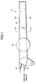
- FIG 1 is a side view of a first embodiment of a water cooled finger according to the present invention.
- Figure 2 is a cross sectional view seen along A-A line of Fig. 1.
- the water cooled finger 11 is formed to be a hollow structure as a whole by welding the steel plates together. With respect to an entire outer configuration, an upper plate 23 and a lower plate 24 are welded to both side plates 21, 22 and further formed in an arm shape by closing a front end part and a base part with other side plates.
- the thus formed hollow part has partitioning plates 31 and 37, and cooling water is caused to successively flow into each of the partitioned chambers 41 to 48.
- the water cooled finger 11 is provided with a central portion 12 of rotation in the base part and with an inlet 13 and an outlet 14 of the cooling water in the base part outside of the shaft.
- the rotating central portion 12 is provided in a shaft wall (not shown). Accordingly, the water cooled finger is opened and closed around a fulcrum of the rotating center portion 12.
- the water cooled finger receives and holds metal materials thrown into a shaft (not shown) under the closing state, and pre-heats metal materials with the high temperature exhaust gas from a furnace (not shown).
- the water cooled finger 11 is formed in that the upper plate 23 thereof is of relatively large thickness, while the lower surface 24 thereof is of relatively small thickness. Namely, a steel plate of relatively large thickness is used for forming the upper plate 23 of the finger 11, and a steel plate of relatively small thickness is used for forming the lower plate 24. In the first embodiment shown in Figs. 1 and 2, the thickness of the lower plate 24 is 1/3 or less than that of the upper plate 23.
- the water cooled finger is given the strength to resist the repeated dropping impact.
- a steel plate of smaller thickness for forming the lower plate 24 the thermal stress therein is reduced. Accordingly, the water cooled finger is given a characteristic durability against repeated thermal stress.
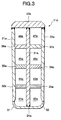
- FIG 3 is a cross sectional view of a second embodiment of a water cooled finger according to the present invention.
- the other structures not explained are the same as those of the water cooled finger shown in Figs. 1 and 2.
- the water cooled finger 11a is formed in that the upper plate 23a thereof is a larger thickness, while the lower plate 24a thereof is of smaller thickness. Namely, a steel plate of larger thickness is employed for forming the upper plate 23a thereof, and a steel plate of smaller thickness is employed for forming the lower plate 24a.
- the thickness of the lower plate 24a is 1/4 or less than that of the upper plate 23a.
- the finger 11a is formed with bent portions 51, 52 having a radius R at both end parts of the lower plate 24a.
- the R-bent portions are arranged at both sides of the steel plate of smaller thickness forming the lower plate 24a so as to raise up both ends toward the side directions. Both raised portions are welded to the side steel plates forming side faces 21a, 22a, resulting in forming the R-bending processed portions 51, 52 at both ends of the lower plate 24a.
- the water cooled finger is given the strength to resist the repeated dropping impact.
- the steel plate of smaller thickness for the lower plate 24a the thermal stress is reduced, and at the same time, the R-bending processed portions 51, 52 are formed at both ends of the face 24a to be concentrated with thermal stress. Accordingly, the water cooled finger is given the characteristic durability against repeated thermal stress.
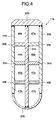
- FIG 4 is a cross sectional view of a third embodiment of a water cooled finger according to the present invention.
- the other structures not explained are the same as those of the water cooled finger shown in Figs. 1 and 2.
- the water cooled finger 11b is formed in that the upper plate 23b thereof is of relatively large thickness, while the lower plate 24b curved outside is of relatively small thickness. Namely, a steel plate of relatively large thickness is employed for forming the upper plate 23b thereof, while a steel plate of relatively small thickness curved outside is employed for forming a lower plate 24b.
- the thickness of the steel plate forming the lower plate 24 b is 1/4 or less than that of the steel plate forming the upper plate 23a.
- Both end portions of the outside curved steel plate of smaller thickness forming the lower plate 24b are welded to side steel plates for forming side faces 21b, 22b, resulting in forming the outside curve of the lower plate 24b.
- the present invention as mentioned above is effective in simultaneously satisfying the strength durable against the repetition of dropping impact when receiving on the water cooled finger metal materials thrown into the shaft as well as the characteristic durability against the repetition of the thermal stress.
Landscapes
- Engineering & Computer Science (AREA)
- Chemical & Material Sciences (AREA)
- Mechanical Engineering (AREA)
- General Engineering & Computer Science (AREA)
- Manufacturing & Machinery (AREA)
- Materials Engineering (AREA)
- Metallurgy (AREA)
- Organic Chemistry (AREA)
- Vertical, Hearth, Or Arc Furnaces (AREA)
- Furnace Details (AREA)
- Waste-Gas Treatment And Other Accessory Devices For Furnaces (AREA)
- Furnace Housings, Linings, Walls, And Ceilings (AREA)
- Manipulator (AREA)
- Commercial Cooking Devices (AREA)
- Furnace Charging Or Discharging (AREA)
- Heat-Exchange Devices With Radiators And Conduit Assemblies (AREA)
Applications Claiming Priority (2)
| Application Number | Priority Date | Filing Date | Title |
|---|---|---|---|
| JP21197398A JP4006748B2 (ja) | 1998-07-10 | 1998-07-10 | 炉頂予熱装置の水冷フィンガー |
| JP21197398 | 1998-07-10 |
Publications (3)
| Publication Number | Publication Date |
|---|---|
| EP0971193A1 true EP0971193A1 (fr) | 2000-01-12 |
| EP0971193B1 EP0971193B1 (fr) | 2003-04-09 |
| EP0971193B2 EP0971193B2 (fr) | 2009-10-07 |
Family
ID=16614783
Family Applications (1)
| Application Number | Title | Priority Date | Filing Date |
|---|---|---|---|
| EP99113259A Expired - Lifetime EP0971193B2 (fr) | 1998-07-10 | 1999-07-08 | Bras refroidi à l'eau |
Country Status (8)
| Country | Link |
|---|---|
| US (1) | US6132206A (fr) |
| EP (1) | EP0971193B2 (fr) |
| JP (1) | JP4006748B2 (fr) |
| CN (1) | CN1163718C (fr) |
| AT (1) | ATE237109T1 (fr) |
| DE (1) | DE69906630T3 (fr) |
| ES (1) | ES2196681T5 (fr) |
| TW (1) | TW403828B (fr) |
Cited By (1)
| Publication number | Priority date | Publication date | Assignee | Title |
|---|---|---|---|---|
| WO2016066163A1 (fr) | 2014-10-28 | 2016-05-06 | Gerhard Fuchs | Dispositif de fusion et procédé de fusion |
Families Citing this family (1)
| Publication number | Priority date | Publication date | Assignee | Title |
|---|---|---|---|---|
| DE102017213201A1 (de) | 2017-07-31 | 2019-01-31 | Sms Group Gmbh | Schrotthaltefinger mit Kühlwasserversorgung |
Citations (3)
| Publication number | Priority date | Publication date | Assignee | Title |
|---|---|---|---|---|
| DE885244C (de) * | 1949-04-27 | 1953-08-03 | Hans Garbeck | Kuehlkasten fuer Hochoefen |
| EP0475009A1 (fr) * | 1990-08-08 | 1992-03-18 | Paul Wurth S.A. | Panneau de refroidissement pour four à cuve |
| JPH1054674A (ja) * | 1996-08-09 | 1998-02-24 | Daido Steel Co Ltd | 予熱装置用ゲート及び予熱装置 |
Family Cites Families (5)
| Publication number | Priority date | Publication date | Assignee | Title |
|---|---|---|---|---|
| DE3713369A1 (de) * | 1987-04-21 | 1988-11-10 | Kortec Ag | Chargiergutvorwaermer zum vorwaermen von chargiergut eines metallurgischen schmelzaggregates |
| LU88399A1 (de) * | 1993-09-01 | 1995-04-05 | Wurth Paul Sa | Verteilerschurre zum Einbau in einen Ofen |
| JP3536365B2 (ja) * | 1994-08-12 | 2004-06-07 | 大同特殊鋼株式会社 | スクラップ予熱装置 |
| JPH08136163A (ja) * | 1994-11-04 | 1996-05-31 | Daido Steel Co Ltd | スクラップ予熱装置の排ガス制御装置 |
| JP3867314B2 (ja) * | 1996-03-21 | 2007-01-10 | 大同特殊鋼株式会社 | 炉頂予熱装置におけるフォーク |
-
1998
- 1998-07-10 JP JP21197398A patent/JP4006748B2/ja not_active Expired - Lifetime
-
1999
- 1999-07-01 US US09/345,768 patent/US6132206A/en not_active Expired - Fee Related
- 1999-07-06 TW TW088111437A patent/TW403828B/zh not_active IP Right Cessation
- 1999-07-08 ES ES99113259T patent/ES2196681T5/es not_active Expired - Lifetime
- 1999-07-08 AT AT99113259T patent/ATE237109T1/de not_active IP Right Cessation
- 1999-07-08 DE DE69906630T patent/DE69906630T3/de not_active Expired - Fee Related
- 1999-07-08 EP EP99113259A patent/EP0971193B2/fr not_active Expired - Lifetime
- 1999-07-09 CN CNB991104218A patent/CN1163718C/zh not_active Expired - Fee Related
Patent Citations (3)
| Publication number | Priority date | Publication date | Assignee | Title |
|---|---|---|---|---|
| DE885244C (de) * | 1949-04-27 | 1953-08-03 | Hans Garbeck | Kuehlkasten fuer Hochoefen |
| EP0475009A1 (fr) * | 1990-08-08 | 1992-03-18 | Paul Wurth S.A. | Panneau de refroidissement pour four à cuve |
| JPH1054674A (ja) * | 1996-08-09 | 1998-02-24 | Daido Steel Co Ltd | 予熱装置用ゲート及び予熱装置 |
Non-Patent Citations (1)
| Title |
|---|
| PATENT ABSTRACTS OF JAPAN vol. 199, no. 806 30 April 1998 (1998-04-30) * |
Cited By (2)
| Publication number | Priority date | Publication date | Assignee | Title |
|---|---|---|---|---|
| WO2016066163A1 (fr) | 2014-10-28 | 2016-05-06 | Gerhard Fuchs | Dispositif de fusion et procédé de fusion |
| DE102014115671A1 (de) | 2014-10-28 | 2016-05-12 | Gerhard Fuchs | Schmelzvorrichtung und schmelzverfahren |
Also Published As
| Publication number | Publication date |
|---|---|
| JP2000028274A (ja) | 2000-01-28 |
| ATE237109T1 (de) | 2003-04-15 |
| DE69906630T3 (de) | 2010-05-06 |
| EP0971193B2 (fr) | 2009-10-07 |
| ES2196681T5 (es) | 2010-02-09 |
| CN1163718C (zh) | 2004-08-25 |
| DE69906630D1 (de) | 2003-05-15 |
| DE69906630T2 (de) | 2003-11-06 |
| CN1243941A (zh) | 2000-02-09 |
| JP4006748B2 (ja) | 2007-11-14 |
| TW403828B (en) | 2000-09-01 |
| ES2196681T3 (es) | 2003-12-16 |
| US6132206A (en) | 2000-10-17 |
| EP0971193B1 (fr) | 2003-04-09 |
Similar Documents
| Publication | Publication Date | Title |
|---|---|---|
| KR20010042420A (ko) | 아크로의 노벽 및 노덮개용 수냉패널 | |
| AU2019290529B2 (en) | Burner panel for a metallurgical furnace | |
| US6609908B2 (en) | Replaceable heater cover | |
| JPH0370989A (ja) | 直立炉用の冷媒を通される冷却素子 | |
| EP0965026A1 (fr) | Panneaux refroidis par liquide a fonctionnement continu | |
| KR100342274B1 (ko) | 용광로용냉각판 | |
| MXPA01001888A (es) | Tubo de intercambio termico con aletas extruidas. | |
| US20260029197A1 (en) | Multi-half pipe heat exchange system for electric arc, metallurgical or refining furnaces and system thereof | |
| US4559011A (en) | Cooling arrangement for shaft furnaces | |
| EP0971193B1 (fr) | Bras refroidi à l'eau | |
| US4182610A (en) | Water-cooled furnace cover | |
| EP0851195A1 (fr) | Rouleau à disques pour le transport de brames | |
| US4435814A (en) | Electric furnace having liquid-cooled vessel walls | |
| US3927959A (en) | Free floating flight in a retort and method | |
| US6640880B1 (en) | Heat exchanger recessed basket lifting cover | |
| JP4473477B2 (ja) | パン生地用ミキサー | |
| KR102482851B1 (ko) | 유리화설비의 저온용융로 및 그 설치방법 | |
| EP1143198A1 (fr) | Appareillage et méthode pour le refroidissement des conduits d'évacuation de fumées | |
| CA1040694A (fr) | Voute de four a arc | |
| US20250224179A1 (en) | Half pipe heat exchange system for electric arc, metallurgical or refining furnaces and system thereof | |
| GB2059556A (en) | Cooling Box for Steel-making Arc Furnace | |
| JPS6027360Y2 (ja) | ア−ク炉水管炉壁 | |
| JPH047519Y2 (fr) | ||
| US3212478A (en) | Brick-lined, water-cooled industrial furnace door | |
| GB1559661A (en) | Cooling assembly for metallurgical vessels |
Legal Events
| Date | Code | Title | Description |
|---|---|---|---|
| PUAI | Public reference made under article 153(3) epc to a published international application that has entered the european phase |
Free format text: ORIGINAL CODE: 0009012 |
|
| AK | Designated contracting states |
Kind code of ref document: A1 Designated state(s): AT DE ES FR IT |
|
| AX | Request for extension of the european patent |
Free format text: AL;LT;LV;MK;RO;SI |
|
| 17P | Request for examination filed |
Effective date: 20000202 |
|
| AKX | Designation fees paid |
Free format text: AT DE ES FR IT |
|
| GRAH | Despatch of communication of intention to grant a patent |
Free format text: ORIGINAL CODE: EPIDOS IGRA |
|
| GRAH | Despatch of communication of intention to grant a patent |
Free format text: ORIGINAL CODE: EPIDOS IGRA |
|
| GRAA | (expected) grant |
Free format text: ORIGINAL CODE: 0009210 |
|
| AK | Designated contracting states |
Designated state(s): AT DE ES FR IT |
|
| REG | Reference to a national code |
Ref country code: ES Ref legal event code: FG2A Ref document number: 2196681 Country of ref document: ES Kind code of ref document: T3 |
|
| PLBI | Opposition filed |
Free format text: ORIGINAL CODE: 0009260 |
|
| PLBQ | Unpublished change to opponent data |
Free format text: ORIGINAL CODE: EPIDOS OPPO |
|
| ET | Fr: translation filed | ||
| PLAX | Notice of opposition and request to file observation + time limit sent |
Free format text: ORIGINAL CODE: EPIDOSNOBS2 |
|
| 26 | Opposition filed |
Opponent name: ARCMET TECHNOLOGIE GMBH Effective date: 20040108 |
|
| PLAX | Notice of opposition and request to file observation + time limit sent |
Free format text: ORIGINAL CODE: EPIDOSNOBS2 |
|
| PLBB | Reply of patent proprietor to notice(s) of opposition received |
Free format text: ORIGINAL CODE: EPIDOSNOBS3 |
|
| PLAB | Opposition data, opponent's data or that of the opponent's representative modified |
Free format text: ORIGINAL CODE: 0009299OPPO |
|
| R26 | Opposition filed (corrected) |
Opponent name: ARCMET TECHNOLOGIE GMBH Effective date: 20040108 |
|
| PLAB | Opposition data, opponent's data or that of the opponent's representative modified |
Free format text: ORIGINAL CODE: 0009299OPPO |
|
| R26 | Opposition filed (corrected) |
Opponent name: ARCMET TECHNOLOGIE GMBH Effective date: 20040108 |
|
| PUAH | Patent maintained in amended form |
Free format text: ORIGINAL CODE: 0009272 |
|
| STAA | Information on the status of an ep patent application or granted ep patent |
Free format text: STATUS: PATENT MAINTAINED AS AMENDED |
|
| 27A | Patent maintained in amended form |
Effective date: 20091007 |
|
| AK | Designated contracting states |
Kind code of ref document: B2 Designated state(s): AT DE ES FR IT |
|
| PGFP | Annual fee paid to national office [announced via postgrant information from national office to epo] |
Ref country code: FR Payment date: 20090710 Year of fee payment: 11 Ref country code: ES Payment date: 20090804 Year of fee payment: 11 |
|
| PGFP | Annual fee paid to national office [announced via postgrant information from national office to epo] |
Ref country code: DE Payment date: 20090702 Year of fee payment: 11 Ref country code: AT Payment date: 20090715 Year of fee payment: 11 |
|
| REG | Reference to a national code |
Ref country code: ES Ref legal event code: DC2A Date of ref document: 20091125 Kind code of ref document: T5 |
|
| PGFP | Annual fee paid to national office [announced via postgrant information from national office to epo] |
Ref country code: IT Payment date: 20090721 Year of fee payment: 11 |
|
| REG | Reference to a national code |
Ref country code: FR Ref legal event code: ST Effective date: 20110331 |
|
| PG25 | Lapsed in a contracting state [announced via postgrant information from national office to epo] |
Ref country code: DE Free format text: LAPSE BECAUSE OF NON-PAYMENT OF DUE FEES Effective date: 20110201 |
|
| REG | Reference to a national code |
Ref country code: DE Ref legal event code: R119 Ref document number: 69906630 Country of ref document: DE Effective date: 20110201 |
|
| PG25 | Lapsed in a contracting state [announced via postgrant information from national office to epo] |
Ref country code: FR Free format text: LAPSE BECAUSE OF NON-PAYMENT OF DUE FEES Effective date: 20100802 Ref country code: AT Free format text: LAPSE BECAUSE OF NON-PAYMENT OF DUE FEES Effective date: 20100708 Ref country code: IT Free format text: LAPSE BECAUSE OF NON-PAYMENT OF DUE FEES Effective date: 20100708 |
|
| REG | Reference to a national code |
Ref country code: ES Ref legal event code: FD2A Effective date: 20110818 |
|
| PG25 | Lapsed in a contracting state [announced via postgrant information from national office to epo] |
Ref country code: ES Free format text: LAPSE BECAUSE OF NON-PAYMENT OF DUE FEES Effective date: 20100709 |