EP0971408A2 - Pièce moulée pour tenir des dissipateurs de chaleur dans un épilement pressé - Google Patents
Pièce moulée pour tenir des dissipateurs de chaleur dans un épilement pressé Download PDFInfo
- Publication number
- EP0971408A2 EP0971408A2 EP99112481A EP99112481A EP0971408A2 EP 0971408 A2 EP0971408 A2 EP 0971408A2 EP 99112481 A EP99112481 A EP 99112481A EP 99112481 A EP99112481 A EP 99112481A EP 0971408 A2 EP0971408 A2 EP 0971408A2
- Authority
- EP
- European Patent Office
- Prior art keywords
- power semiconductor
- semiconductor component
- molded part
- holding
- lhe
- Prior art date
- Legal status (The legal status is an assumption and is not a legal conclusion. Google has not performed a legal analysis and makes no representation as to the accuracy of the status listed.)
- Granted
Links
Images


Classifications
-
- H—ELECTRICITY
- H10—SEMICONDUCTOR DEVICES; ELECTRIC SOLID-STATE DEVICES NOT OTHERWISE PROVIDED FOR
- H10W—GENERIC PACKAGES, INTERCONNECTIONS, CONNECTORS OR OTHER CONSTRUCTIONAL DETAILS OF DEVICES COVERED BY CLASS H10
- H10W78/00—Detachable holders for supporting packaged chips in operation
-
- H—ELECTRICITY
- H10—SEMICONDUCTOR DEVICES; ELECTRIC SOLID-STATE DEVICES NOT OTHERWISE PROVIDED FOR
- H10W—GENERIC PACKAGES, INTERCONNECTIONS, CONNECTORS OR OTHER CONSTRUCTIONAL DETAILS OF DEVICES COVERED BY CLASS H10
- H10W90/00—Package configurations
-
- H—ELECTRICITY
- H10—SEMICONDUCTOR DEVICES; ELECTRIC SOLID-STATE DEVICES NOT OTHERWISE PROVIDED FOR
- H10W—GENERIC PACKAGES, INTERCONNECTIONS, CONNECTORS OR OTHER CONSTRUCTIONAL DETAILS OF DEVICES COVERED BY CLASS H10
- H10W40/00—Arrangements for thermal protection or thermal control
- H10W40/40—Arrangements for thermal protection or thermal control involving heat exchange by flowing fluids
- H10W40/47—Arrangements for thermal protection or thermal control involving heat exchange by flowing fluids by flowing liquids, e.g. forced water cooling
Definitions
- the present invention relates to the field of power semiconductor technology. It relates to a holder for heat sinks according to the preamble of claim 1, for preference Use in a semiconductor clamping stack, in particular for high-performance converters.
- a semiconductor clamping stack is e.g. from the publication P. Steimer et al. "Series connection of GTO thyristors for frequency converters high performance ", ABB Review 5 (1996), pp. 14-20.
- cooling water drainage, feed and Control cable For holding and centering the cooling boxes and the Power semiconductor components and for fixing the cooling water supply, cooling water drainage, feed and Control cable is provided a variety of plastic parts. These separate brackets require increased assembly effort and are a quick replacement of individual components not useful.
- LHE individual power semiconductor components
- the task is solved by a new molded part for simultaneous Bracket and centering a heat sink as well of a LHE directly adjacent to it.
- This will make one created new base unit consisting of the inventive Molding, an LHE and a heat sink, which maximum flexibility when building a multi-component Spannstapels offered.
- the LHE and the heat sink are like this positioned that an electrode of the LHE and a cooling surface of the heat sink are congruent with each other. At the An electrode and an electrode are clamped in each case Cooling surface pressed together, whereby the thermal and electrical conductivity between the components of the stack is optimized.
- a first preferred embodiment is characterized in that both the heat sink and the LHE by one snap-in detachable closure with the inventive Molded part are connected. This allows easy replacement especially the LHE by the appropriate Closure as a result of sufficient traction on the LHE this releases again.
- a second preferred embodiment is characterized in that that in addition to the stack-centered end position
- the two components also determine how this end position can be reached.
- the invention provides for this the existence of installation aids for the LHE, which guide means in the molded part according to the invention and firmly on the LHE include mounted guide elements.
- the latter are for example designed as knobs or wings and directly with the LHE connected, they become a molded part by a corresponding corresponding counterpart (guide means) in the form of a Rail or groove directed.
- this guide can be used during expansion of an LHE from the molded part the LHE are guided so that the Contact surface of the heat sink and the electrode of the LHE are not to be damaged.
- the entire stack is first relaxed and the individual, movable parallel to the stack axis (because for example, those running parallel to the stack Base units guided) slightly apart from each other Cut.
- the LHE is thanks to the Guide means shifted so that its electrode is inclined from the corresponding contact surface of the heat sink is separated and therefore cannot scratch it.
- This will be simple Kind realized for example by a guide groove, which is not parallel to the contact surface of the heat sink.
- a next preferred embodiment relates to the use of LHE of the type described above, in which the Semiconductor together with its control on one Board is located.
- the guide elements not attached directly to the LHE but to the circuit board and also serve to mechanically support the control unit. If necessary, the board itself can be the guide element be and inserted directly into corresponding guide grooves become.
- Fig.1 and Fig.2 is a preferred perspective view Embodiment of a molded part 10 according to the invention along with some components of cooling device 30 reproduced.
- FIG. 2 there is also a power semiconductor component (LHE) 41 shown which is fixed to a circuit board 43 is connected.
- LHE power semiconductor component
- the cooling device 30 comprises a water-flushed cooling box 31 which on the corresponding holder 11 of the invention Molding 10 is mounted.
- the cooling water supply and derivatives 36,37 between the cooling box 31 and the cooling water distribution pipe (not shown) and the cooling water manifold 35 may need to be of a certain minimum length. This is because of a potential difference between the cooling box 31 and the electrically conductive tube 35 a corrosive Electrolysis current is driven, which one must not exceed a certain value. To the necessary To reach length, the lines 36,37 can spiral be trained. Their brackets 14, 15 prevent that two at different electrostatic potential Touch the points of the cooling water pipes.
- the LHE 41 is housed in a cylindrical housing, which on both ends for electrical and thermal Coupling with flat, circular electrodes 42 (anodes, Cathodes) is provided.
- the semiconductor stack is on Both sides of the LHE also have a cylindrical cooling socket 31 arranged such that their contact surfaces 32, 33 with the Electrodes 42 of the LHE come into contact.
- An LHE is added to the molded part according to the invention an adjacent cooling box combined in pairs.
- the LHE 41 shown in FIG. 2 is a GTO thyristor firmly connected to a circuit board 43.
- the central part of the bracket 12, 13 is a snap lock 18, 19, the counterpart 45 on the Board 43 is mounted.
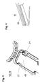
- Such a snap lock is in Fig. 3 shown together with its counterpart 45, which inserted into the closure and from the two tabs 21 is held. These in turn are dimensioned so that the counterpart 45 and thus the LHE when subjected to tensile stress Release 41 again.
- the LHE 41 When installing, the LHE 41 is not opened directly, but by means of the circuit board 43 mounted guide elements (not shown) guided.
- the relevant management tools 16, 17 as part of the molded part 10 have the shape of wing-shaped extensions.
- the LHE By the inclination of this Groove, the LHE is moved so that its electrode 42 the Contact surface 33 of the cooling box 31 only when the end position is reached touched and previously any friction between the two surfaces 42.33 is avoided.
- the circuit board and the control unit 44 located thereon additionally supported by the guide means 16, 17 and mechanically stabilized.
- the device according to the invention is made of electrically insulating Material, preferably plastic, made and can be produced inexpensively by injection molding.
- control unit 44 is also contained on the circuit board 43 there is another one for replacing an LHE 41 Simplification in that the contact device 22 for the supply of the control unit 44 into the molded part 10 is integrated.
- the feed cable 23 is preferably through a recess in the molded part leads up to a bushing 24, which is firmly anchored in the molded part.
- a plug 46 as its counterpart is on the board 43.
- the tie rods required to brace the stack run parallel to the stack.
- they are formed as tubes 35 and at the same time serve for distribution and collecting the cooling water.
- the Molded parts according to the invention mounted so that the of them held components are centered in the stack.
- Fig.1 is can be seen how a molded part on the cooling water header 35 is attached by means of a clip fastener 25, 26.
- the molded parts in the direction of the stacking axis are not completely blocked because they are in the Tension and relaxation of the stack can still move have to.
- the clip fastener 25.26 must be subjected to tensile forces in the plane perpendicular to the stack or to the cooling water pipe be resilient, i.e. under no circumstances should it be subject to tensile loads Give in earlier than the snap lock 18, 19.
Landscapes
- Cooling Or The Like Of Semiconductors Or Solid State Devices (AREA)
- Rectifiers (AREA)
- Encapsulation Of And Coatings For Semiconductor Or Solid State Devices (AREA)
Applications Claiming Priority (2)
| Application Number | Priority Date | Filing Date | Title |
|---|---|---|---|
| DE19830424A DE19830424A1 (de) | 1998-07-08 | 1998-07-08 | Formteil zur Halterung von Kühlkörpern in einem Spannstapel |
| DE19830424 | 1998-07-08 |
Publications (3)
| Publication Number | Publication Date |
|---|---|
| EP0971408A2 true EP0971408A2 (fr) | 2000-01-12 |
| EP0971408A3 EP0971408A3 (fr) | 2001-10-17 |
| EP0971408B1 EP0971408B1 (fr) | 2003-09-17 |
Family
ID=7873285
Family Applications (1)
| Application Number | Title | Priority Date | Filing Date |
|---|---|---|---|
| EP99112481A Expired - Lifetime EP0971408B1 (fr) | 1998-07-08 | 1999-07-01 | Pièce moulée pour tenir des dissipateurs de chaleur dans un épilement pressé |
Country Status (6)
| Country | Link |
|---|---|
| US (1) | US6140699A (fr) |
| EP (1) | EP0971408B1 (fr) |
| JP (1) | JP4365938B2 (fr) |
| KR (1) | KR100576285B1 (fr) |
| CA (1) | CA2276885C (fr) |
| DE (2) | DE19830424A1 (fr) |
Cited By (2)
| Publication number | Priority date | Publication date | Assignee | Title |
|---|---|---|---|---|
| EP1178593A1 (fr) * | 2000-08-02 | 2002-02-06 | ABB Industrie AG | Empilement pressé pour semi-conducteurs |
| WO2015124511A1 (fr) * | 2014-02-21 | 2015-08-27 | Maschinenfabrik Reinhausen Gmbh | Dispositif de commutation |
Families Citing this family (4)
| Publication number | Priority date | Publication date | Assignee | Title |
|---|---|---|---|---|
| FR2900766B1 (fr) * | 2006-05-04 | 2008-09-26 | Converteam Sas | Dispositif et procede de centrage d'un element a semi-conducteur destine a etre insere dans un ensemble a empilement presse et ensemble a empilement presse comportant un tel dispositif |
| FR2900767A1 (fr) * | 2006-05-04 | 2007-11-09 | Converteam Sas Soc Par Actions | Macro-composant destine a etre monte dans un ensemble a empilement presse et ensemble comportant un tel macro-composant |
| DE102011006990B4 (de) * | 2011-04-07 | 2015-03-26 | Siemens Aktiengesellschaft | Kühldoseneinheit |
| KR102055678B1 (ko) * | 2018-10-11 | 2019-12-13 | 엘지전자 주식회사 | 정수기 |
Family Cites Families (9)
| Publication number | Priority date | Publication date | Assignee | Title |
|---|---|---|---|---|
| DE6945492U (de) * | 1969-11-18 | 1970-03-26 | Licentia Gmbh | Stromrichter- oder stromstellergeraet mit wassergekuehlten leistungshalbleitern |
| GB1518138A (en) * | 1974-12-17 | 1978-07-19 | Thomson Csf | Cooling device for components which dissipate large amounts of heat |
| JPS59119858A (ja) * | 1982-12-27 | 1984-07-11 | Toshiba Corp | 液冷式半導体スタツク |
| SE441047B (sv) * | 1983-10-06 | 1985-09-02 | Asea Ab | Halvledarventil for hogspenning med spenningsdelarsektioner innefattande motstand |
| DE4025885C2 (de) * | 1990-08-16 | 1994-09-08 | Gewerk Auguste Victoria | Halbleitersäule |
| KR960001605B1 (ko) * | 1990-09-13 | 1996-02-02 | 후지쓰 가부시끼가이샤 | 방열핀 조립체를 구비한 반도체장치 및 이를 수용하기 위한 용기 |
| JPH0992782A (ja) * | 1995-09-21 | 1997-04-04 | Mitsubishi Electric Corp | 半導体素子交換治具および半導体素子交換方法 |
| FR2751132A1 (fr) * | 1996-07-09 | 1998-01-16 | Gec Alsthom Transport Sa | Plaque a fluide de refroidissement et dispositif a semi-conducteurs de puissance comportant une telle plaque |
| JPH11307682A (ja) * | 1998-04-23 | 1999-11-05 | Hitachi Ltd | 半導体装置 |
-
1998
- 1998-07-08 DE DE19830424A patent/DE19830424A1/de not_active Withdrawn
-
1999
- 1999-07-01 US US09/345,510 patent/US6140699A/en not_active Expired - Lifetime
- 1999-07-01 DE DE59906993T patent/DE59906993D1/de not_active Expired - Lifetime
- 1999-07-01 EP EP99112481A patent/EP0971408B1/fr not_active Expired - Lifetime
- 1999-07-01 JP JP18757999A patent/JP4365938B2/ja not_active Expired - Fee Related
- 1999-07-02 CA CA002276885A patent/CA2276885C/fr not_active Expired - Fee Related
- 1999-07-07 KR KR1019990027266A patent/KR100576285B1/ko not_active Expired - Fee Related
Cited By (4)
| Publication number | Priority date | Publication date | Assignee | Title |
|---|---|---|---|---|
| EP1178593A1 (fr) * | 2000-08-02 | 2002-02-06 | ABB Industrie AG | Empilement pressé pour semi-conducteurs |
| US6495913B2 (en) | 2000-08-02 | 2002-12-17 | Abb Industrie Ag | Semiconductor clamped-stack assembly |
| WO2015124511A1 (fr) * | 2014-02-21 | 2015-08-27 | Maschinenfabrik Reinhausen Gmbh | Dispositif de commutation |
| RU2678084C2 (ru) * | 2014-02-21 | 2019-01-23 | Машиненфабрик Райнхаузен Гмбх | Коммутационное устройство |
Also Published As
| Publication number | Publication date |
|---|---|
| EP0971408A3 (fr) | 2001-10-17 |
| CA2276885A1 (fr) | 2000-01-08 |
| US6140699A (en) | 2000-10-31 |
| CA2276885C (fr) | 2008-06-10 |
| DE19830424A1 (de) | 2000-01-13 |
| KR100576285B1 (ko) | 2006-05-04 |
| JP4365938B2 (ja) | 2009-11-18 |
| JP2000036553A (ja) | 2000-02-02 |
| EP0971408B1 (fr) | 2003-09-17 |
| DE59906993D1 (de) | 2003-10-23 |
| KR20000011550A (ko) | 2000-02-25 |
Similar Documents
| Publication | Publication Date | Title |
|---|---|---|
| DE102018110361B4 (de) | Montagebaugruppe mit bedrahteten elektronischen Leistungsbauteilen und deren Zusammenbau mit einem Motorgehäuse | |
| DE2354663C3 (de) | Stromrichter | |
| DE10001184A1 (de) | Vorrichtung zum Verbinden von Stromsammelschienen eines Sammelschienensystems mit den Anschlusskontakten eines elektrischen Installationsgerätes | |
| DE10003900B4 (de) | Stromübertragungsanordnung | |
| DE102015217790B4 (de) | Anordnung zur Kühlung von Batteriezellen eines Antriebsenergiespeichers eines Kraftfahrzeuges | |
| EP1178593A1 (fr) | Empilement pressé pour semi-conducteurs | |
| EP0971408B1 (fr) | Pièce moulée pour tenir des dissipateurs de chaleur dans un épilement pressé | |
| DE2838966A1 (de) | Halte- und lagereinrichtung fuer bauelemente bei elektrischen maschinen, insbesondere fuer drehstromgenerator | |
| DE2103923C3 (de) | Befestigungsanordnung | |
| DE2218612A1 (de) | Gleichrichteranordnung mit gekühlter Stromzuführung | |
| DE19910787B4 (de) | Umformer für einen Drehstrommotor in Flurförderzeugen | |
| DE102013015753B4 (de) | Zellblock für eine Batterie und Batterie | |
| DE102016115898B4 (de) | Anordnung zur Befestigung von Leiterplatten | |
| WO2005096478A1 (fr) | Stator long comportant une ligne de terre et train a sustentation magnetique equipe de ce stator | |
| DE102013015758A1 (de) | Batterie und Zellblock für eine Batterie | |
| DE102018124028A1 (de) | Sensorvorrichtung, spannungsversorgungssystem und verfahren | |
| DE102020101331B4 (de) | Invertervorrichtung mit einer Kühlung | |
| DE69619955T2 (de) | Aus elementaren Dioden aufgebaute schnelle Diode mit höher Durchbruchspannung und höher direkter Stromzulässigkeit | |
| DE19935803A1 (de) | Schaltanlage mit Stromschiene und Wärmeableitvorrichtung | |
| DE102024138897B3 (de) | Beleuchtungsanordnung zum Abhängen von einer Decke eines Gebäudes | |
| DE60018149T2 (de) | Steuereinheit für elektronische Motoren einschliesslich einer Leiterplatte mit Stromschienen | |
| DE10034421B4 (de) | Induktor | |
| DE102024138895B3 (de) | Beleuchtungsanordnung zum Abhängen von einer Decke eines Gebäudes | |
| DE69225991T2 (de) | Sammelschienenverteilungssystem | |
| DE10159294A1 (de) | Stromschienenbefestigung |
Legal Events
| Date | Code | Title | Description |
|---|---|---|---|
| PUAI | Public reference made under article 153(3) epc to a published international application that has entered the european phase |
Free format text: ORIGINAL CODE: 0009012 |
|
| AK | Designated contracting states |
Kind code of ref document: A2 Designated state(s): AT BE CH CY DE DK ES FI FR GB GR IE IT LI LU MC NL PT SE Kind code of ref document: A2 Designated state(s): DE FR GB IT |
|
| AX | Request for extension of the european patent |
Free format text: AL;LT;LV;MK;RO;SI |
|
| RAP1 | Party data changed (applicant data changed or rights of an application transferred) |
Owner name: ABB INDUSTRIE AG |
|
| PUAL | Search report despatched |
Free format text: ORIGINAL CODE: 0009013 |
|
| AK | Designated contracting states |
Kind code of ref document: A3 Designated state(s): AT BE CH CY DE DK ES FI FR GB GR IE IT LI LU MC NL PT SE |
|
| AX | Request for extension of the european patent |
Free format text: AL;LT;LV;MK;RO;SI |
|
| RAP1 | Party data changed (applicant data changed or rights of an application transferred) |
Owner name: ABB SCHWEIZ AG |
|
| 17P | Request for examination filed |
Effective date: 20020402 |
|
| AKX | Designation fees paid |
Free format text: DE FR GB IT |
|
| GRAH | Despatch of communication of intention to grant a patent |
Free format text: ORIGINAL CODE: EPIDOS IGRA |
|
| GRAH | Despatch of communication of intention to grant a patent |
Free format text: ORIGINAL CODE: EPIDOS IGRA |
|
| GRAA | (expected) grant |
Free format text: ORIGINAL CODE: 0009210 |
|
| AK | Designated contracting states |
Kind code of ref document: B1 Designated state(s): DE FR GB IT |
|
| PG25 | Lapsed in a contracting state [announced via postgrant information from national office to epo] |
Ref country code: IT Free format text: LAPSE BECAUSE OF FAILURE TO SUBMIT A TRANSLATION OF THE DESCRIPTION OR TO PAY THE FEE WITHIN THE PRE;WARNING: LAPSES OF ITALIAN PATENTS WITH EFFECTIVE DATE BEFORE 2007 MAY HAVE OCCURRED AT ANY TIME BEFORE 2007. THE CORRECT EFFECTIVE DATE MAY BE DIFFERENT FROM THE ONE RECORDED.SCRIBED TIME-LIMIT Effective date: 20030917 Ref country code: GB Free format text: LAPSE BECAUSE OF FAILURE TO SUBMIT A TRANSLATION OF THE DESCRIPTION OR TO PAY THE FEE WITHIN THE PRESCRIBED TIME-LIMIT Effective date: 20030917 |
|
| REG | Reference to a national code |
Ref country code: GB Ref legal event code: FG4D Free format text: NOT ENGLISH |
|
| REF | Corresponds to: |
Ref document number: 59906993 Country of ref document: DE Date of ref document: 20031023 Kind code of ref document: P |
|
| GBV | Gb: ep patent (uk) treated as always having been void in accordance with gb section 77(7)/1977 [no translation filed] |
Effective date: 20030917 |
|
| ET | Fr: translation filed | ||
| PLBE | No opposition filed within time limit |
Free format text: ORIGINAL CODE: 0009261 |
|
| STAA | Information on the status of an ep patent application or granted ep patent |
Free format text: STATUS: NO OPPOSITION FILED WITHIN TIME LIMIT |
|
| 26N | No opposition filed |
Effective date: 20040618 |
|
| PGFP | Annual fee paid to national office [announced via postgrant information from national office to epo] |
Ref country code: DE Payment date: 20140721 Year of fee payment: 16 |
|
| PGFP | Annual fee paid to national office [announced via postgrant information from national office to epo] |
Ref country code: FR Payment date: 20150626 Year of fee payment: 17 |
|
| REG | Reference to a national code |
Ref country code: DE Ref legal event code: R119 Ref document number: 59906993 Country of ref document: DE |
|
| PG25 | Lapsed in a contracting state [announced via postgrant information from national office to epo] |
Ref country code: DE Free format text: LAPSE BECAUSE OF NON-PAYMENT OF DUE FEES Effective date: 20160202 |
|
| REG | Reference to a national code |
Ref country code: FR Ref legal event code: ST Effective date: 20160331 |
|
| PG25 | Lapsed in a contracting state [announced via postgrant information from national office to epo] |
Ref country code: FR Free format text: LAPSE BECAUSE OF NON-PAYMENT OF DUE FEES Effective date: 20150731 |