EP0971419A2 - Système thermovoltaque dynamique - Google Patents
Système thermovoltaque dynamique Download PDFInfo
- Publication number
- EP0971419A2 EP0971419A2 EP99500098A EP99500098A EP0971419A2 EP 0971419 A2 EP0971419 A2 EP 0971419A2 EP 99500098 A EP99500098 A EP 99500098A EP 99500098 A EP99500098 A EP 99500098A EP 0971419 A2 EP0971419 A2 EP 0971419A2
- Authority
- EP
- European Patent Office
- Prior art keywords
- integrated
- thermophotovoltaic
- fact
- circuit
- building
- Prior art date
- Legal status (The legal status is an assumption and is not a legal conclusion. Google has not performed a legal analysis and makes no representation as to the accuracy of the status listed.)
- Withdrawn
Links
- 239000007788 liquid Substances 0.000 claims abstract description 37
- 239000011521 glass Substances 0.000 claims description 21
- 238000010438 heat treatment Methods 0.000 claims description 14
- 239000000463 material Substances 0.000 claims description 9
- 230000005855 radiation Effects 0.000 claims description 9
- 230000005496 eutectics Effects 0.000 claims description 7
- LYCAIKOWRPUZTN-UHFFFAOYSA-N Ethylene glycol Chemical compound OCCO LYCAIKOWRPUZTN-UHFFFAOYSA-N 0.000 claims description 6
- 230000008018 melting Effects 0.000 claims description 5
- 238000002844 melting Methods 0.000 claims description 5
- 238000000034 method Methods 0.000 claims description 5
- 230000008901 benefit Effects 0.000 claims description 4
- 239000004020 conductor Substances 0.000 claims description 4
- 229910052751 metal Inorganic materials 0.000 claims description 4
- GWEVSGVZZGPLCZ-UHFFFAOYSA-N Titan oxide Chemical compound O=[Ti]=O GWEVSGVZZGPLCZ-UHFFFAOYSA-N 0.000 claims description 3
- 238000001816 cooling Methods 0.000 claims description 3
- WGCNASOHLSPBMP-UHFFFAOYSA-N hydroxyacetaldehyde Natural products OCC=O WGCNASOHLSPBMP-UHFFFAOYSA-N 0.000 claims description 3
- 239000000203 mixture Substances 0.000 claims description 3
- WOCIAKWEIIZHES-UHFFFAOYSA-N ruthenium(iv) oxide Chemical compound O=[Ru]=O WOCIAKWEIIZHES-UHFFFAOYSA-N 0.000 claims description 3
- 229920000914 Metallic fiber Polymers 0.000 claims description 2
- 239000008151 electrolyte solution Substances 0.000 claims description 2
- 238000012986 modification Methods 0.000 claims description 2
- 230000004048 modification Effects 0.000 claims description 2
- 229920006395 saturated elastomer Polymers 0.000 claims description 2
- RTAQQCXQSZGOHL-UHFFFAOYSA-N Titanium Chemical compound [Ti] RTAQQCXQSZGOHL-UHFFFAOYSA-N 0.000 claims 1
- 230000008014 freezing Effects 0.000 claims 1
- 238000007710 freezing Methods 0.000 claims 1
- 150000002484 inorganic compounds Chemical class 0.000 claims 1
- 150000002894 organic compounds Chemical class 0.000 claims 1
- 229920000642 polymer Polymers 0.000 claims 1
- 238000004064 recycling Methods 0.000 claims 1
- 150000003839 salts Chemical class 0.000 claims 1
- RAHZWNYVWXNFOC-UHFFFAOYSA-N sulfur dioxide Inorganic materials O=S=O RAHZWNYVWXNFOC-UHFFFAOYSA-N 0.000 claims 1
- 239000000725 suspension Substances 0.000 claims 1
- 229910052719 titanium Inorganic materials 0.000 claims 1
- 239000010936 titanium Substances 0.000 claims 1
- 238000009434 installation Methods 0.000 description 7
- 239000012530 fluid Substances 0.000 description 6
- 238000005192 partition Methods 0.000 description 4
- XLYOFNOQVPJJNP-UHFFFAOYSA-N water Substances O XLYOFNOQVPJJNP-UHFFFAOYSA-N 0.000 description 4
- FAPWRFPIFSIZLT-UHFFFAOYSA-M Sodium chloride Chemical compound [Na+].[Cl-] FAPWRFPIFSIZLT-UHFFFAOYSA-M 0.000 description 2
- 238000009825 accumulation Methods 0.000 description 2
- 230000009471 action Effects 0.000 description 2
- 239000004411 aluminium Substances 0.000 description 2
- 229910052782 aluminium Inorganic materials 0.000 description 2
- 230000005611 electricity Effects 0.000 description 2
- 239000002184 metal Substances 0.000 description 2
- 239000011780 sodium chloride Substances 0.000 description 2
- 239000000243 solution Substances 0.000 description 2
- 230000032258 transport Effects 0.000 description 2
- 238000009423 ventilation Methods 0.000 description 2
- 238000001429 visible spectrum Methods 0.000 description 2
- 230000006978 adaptation Effects 0.000 description 1
- VRAIHTAYLFXSJJ-UHFFFAOYSA-N alumane Chemical compound [AlH3].[AlH3] VRAIHTAYLFXSJJ-UHFFFAOYSA-N 0.000 description 1
- XAGFODPZIPBFFR-UHFFFAOYSA-N aluminium Chemical compound [Al] XAGFODPZIPBFFR-UHFFFAOYSA-N 0.000 description 1
- 230000004888 barrier function Effects 0.000 description 1
- 230000033228 biological regulation Effects 0.000 description 1
- 238000000576 coating method Methods 0.000 description 1
- 238000004891 communication Methods 0.000 description 1
- 150000001875 compounds Chemical class 0.000 description 1
- 230000000694 effects Effects 0.000 description 1
- 239000003792 electrolyte Substances 0.000 description 1
- 238000005516 engineering process Methods 0.000 description 1
- 239000000374 eutectic mixture Substances 0.000 description 1
- 210000004072 lung Anatomy 0.000 description 1
- 229910044991 metal oxide Inorganic materials 0.000 description 1
- 150000002739 metals Chemical class 0.000 description 1
- 239000000049 pigment Substances 0.000 description 1
- 239000004417 polycarbonate Substances 0.000 description 1
- 229920000515 polycarbonate Polymers 0.000 description 1
- 230000001105 regulatory effect Effects 0.000 description 1
- 239000000126 substance Substances 0.000 description 1
- 238000006467 substitution reaction Methods 0.000 description 1
- 230000028016 temperature homeostasis Effects 0.000 description 1
- 239000012780 transparent material Substances 0.000 description 1
- 238000003466 welding Methods 0.000 description 1
Images





Classifications
-
- F—MECHANICAL ENGINEERING; LIGHTING; HEATING; WEAPONS; BLASTING
- F24—HEATING; RANGES; VENTILATING
- F24D—DOMESTIC- OR SPACE-HEATING SYSTEMS, e.g. CENTRAL HEATING SYSTEMS; DOMESTIC HOT-WATER SUPPLY SYSTEMS; ELEMENTS OR COMPONENTS THEREFOR
- F24D17/00—Domestic hot-water supply systems
- F24D17/0015—Domestic hot-water supply systems using solar energy
- F24D17/0021—Domestic hot-water supply systems using solar energy with accumulation of the heated water
-
- F—MECHANICAL ENGINEERING; LIGHTING; HEATING; WEAPONS; BLASTING
- F24—HEATING; RANGES; VENTILATING
- F24D—DOMESTIC- OR SPACE-HEATING SYSTEMS, e.g. CENTRAL HEATING SYSTEMS; DOMESTIC HOT-WATER SUPPLY SYSTEMS; ELEMENTS OR COMPONENTS THEREFOR
- F24D11/00—Central heating systems using heat accumulated in storage masses
- F24D11/002—Central heating systems using heat accumulated in storage masses water heating system
- F24D11/003—Central heating systems using heat accumulated in storage masses water heating system combined with solar energy
-
- F—MECHANICAL ENGINEERING; LIGHTING; HEATING; WEAPONS; BLASTING
- F24—HEATING; RANGES; VENTILATING
- F24D—DOMESTIC- OR SPACE-HEATING SYSTEMS, e.g. CENTRAL HEATING SYSTEMS; DOMESTIC HOT-WATER SUPPLY SYSTEMS; ELEMENTS OR COMPONENTS THEREFOR
- F24D18/00—Small-scale combined heat and power [CHP] generation systems specially adapted for domestic heating, space heating or domestic hot-water supply
-
- H—ELECTRICITY
- H02—GENERATION; CONVERSION OR DISTRIBUTION OF ELECTRIC POWER
- H02S—GENERATION OF ELECTRIC POWER BY CONVERSION OF INFRARED RADIATION, VISIBLE LIGHT OR ULTRAVIOLET LIGHT, e.g. USING PHOTOVOLTAIC [PV] MODULES
- H02S40/00—Components or accessories in combination with PV modules, not provided for in groups H02S10/00 - H02S30/00
- H02S40/40—Thermal components
- H02S40/44—Means to utilise heat energy, e.g. hybrid systems producing warm water and electricity at the same time
-
- H—ELECTRICITY
- H10—SEMICONDUCTOR DEVICES; ELECTRIC SOLID-STATE DEVICES NOT OTHERWISE PROVIDED FOR
- H10F—INORGANIC SEMICONDUCTOR DEVICES SENSITIVE TO INFRARED RADIATION, LIGHT, ELECTROMAGNETIC RADIATION OF SHORTER WAVELENGTH OR CORPUSCULAR RADIATION
- H10F77/00—Constructional details of devices covered by this subclass
- H10F77/60—Arrangements for cooling, heating, ventilating or compensating for temperature fluctuations
- H10F77/63—Arrangements for cooling directly associated or integrated with photovoltaic cells, e.g. heat sinks directly associated with the photovoltaic cells or integrated Peltier elements for active cooling
- H10F77/68—Arrangements for cooling directly associated or integrated with photovoltaic cells, e.g. heat sinks directly associated with the photovoltaic cells or integrated Peltier elements for active cooling using gaseous or liquid coolants, e.g. air flow ventilation or water circulation
-
- F—MECHANICAL ENGINEERING; LIGHTING; HEATING; WEAPONS; BLASTING
- F24—HEATING; RANGES; VENTILATING
- F24D—DOMESTIC- OR SPACE-HEATING SYSTEMS, e.g. CENTRAL HEATING SYSTEMS; DOMESTIC HOT-WATER SUPPLY SYSTEMS; ELEMENTS OR COMPONENTS THEREFOR
- F24D2101/00—Electric generators of small-scale CHP systems
- F24D2101/40—Photovoltaic [PV] modules
-
- F—MECHANICAL ENGINEERING; LIGHTING; HEATING; WEAPONS; BLASTING
- F24—HEATING; RANGES; VENTILATING
- F24S—SOLAR HEAT COLLECTORS; SOLAR HEAT SYSTEMS
- F24S10/00—Solar heat collectors using working fluids
- F24S10/20—Solar heat collectors using working fluids having circuits for two or more working fluids
-
- F—MECHANICAL ENGINEERING; LIGHTING; HEATING; WEAPONS; BLASTING
- F24—HEATING; RANGES; VENTILATING
- F24S—SOLAR HEAT COLLECTORS; SOLAR HEAT SYSTEMS
- F24S10/00—Solar heat collectors using working fluids
- F24S10/70—Solar heat collectors using working fluids the working fluids being conveyed through tubular absorbing conduits
- F24S10/72—Solar heat collectors using working fluids the working fluids being conveyed through tubular absorbing conduits the tubular conduits being integrated in a block; the tubular conduits touching each other
-
- F—MECHANICAL ENGINEERING; LIGHTING; HEATING; WEAPONS; BLASTING
- F24—HEATING; RANGES; VENTILATING
- F24S—SOLAR HEAT COLLECTORS; SOLAR HEAT SYSTEMS
- F24S20/00—Solar heat collectors specially adapted for particular uses or environments
- F24S20/60—Solar heat collectors integrated in fixed constructions, e.g. in buildings
- F24S20/66—Solar heat collectors integrated in fixed constructions, e.g. in buildings in the form of facade constructions, e.g. wall constructions
-
- F—MECHANICAL ENGINEERING; LIGHTING; HEATING; WEAPONS; BLASTING
- F24—HEATING; RANGES; VENTILATING
- F24S—SOLAR HEAT COLLECTORS; SOLAR HEAT SYSTEMS
- F24S20/00—Solar heat collectors specially adapted for particular uses or environments
- F24S2020/10—Solar modules layout; Modular arrangements
- F24S2020/17—Arrangements of solar thermal modules combined with solar PV modules
-
- Y—GENERAL TAGGING OF NEW TECHNOLOGICAL DEVELOPMENTS; GENERAL TAGGING OF CROSS-SECTIONAL TECHNOLOGIES SPANNING OVER SEVERAL SECTIONS OF THE IPC; TECHNICAL SUBJECTS COVERED BY FORMER USPC CROSS-REFERENCE ART COLLECTIONS [XRACs] AND DIGESTS
- Y02—TECHNOLOGIES OR APPLICATIONS FOR MITIGATION OR ADAPTATION AGAINST CLIMATE CHANGE
- Y02A—TECHNOLOGIES FOR ADAPTATION TO CLIMATE CHANGE
- Y02A30/00—Adapting or protecting infrastructure or their operation
- Y02A30/60—Planning or developing urban green infrastructure
-
- Y—GENERAL TAGGING OF NEW TECHNOLOGICAL DEVELOPMENTS; GENERAL TAGGING OF CROSS-SECTIONAL TECHNOLOGIES SPANNING OVER SEVERAL SECTIONS OF THE IPC; TECHNICAL SUBJECTS COVERED BY FORMER USPC CROSS-REFERENCE ART COLLECTIONS [XRACs] AND DIGESTS
- Y02—TECHNOLOGIES OR APPLICATIONS FOR MITIGATION OR ADAPTATION AGAINST CLIMATE CHANGE
- Y02B—CLIMATE CHANGE MITIGATION TECHNOLOGIES RELATED TO BUILDINGS, e.g. HOUSING, HOUSE APPLIANCES OR RELATED END-USER APPLICATIONS
- Y02B10/00—Integration of renewable energy sources in buildings
- Y02B10/20—Solar thermal
-
- Y—GENERAL TAGGING OF NEW TECHNOLOGICAL DEVELOPMENTS; GENERAL TAGGING OF CROSS-SECTIONAL TECHNOLOGIES SPANNING OVER SEVERAL SECTIONS OF THE IPC; TECHNICAL SUBJECTS COVERED BY FORMER USPC CROSS-REFERENCE ART COLLECTIONS [XRACs] AND DIGESTS
- Y02—TECHNOLOGIES OR APPLICATIONS FOR MITIGATION OR ADAPTATION AGAINST CLIMATE CHANGE
- Y02B—CLIMATE CHANGE MITIGATION TECHNOLOGIES RELATED TO BUILDINGS, e.g. HOUSING, HOUSE APPLIANCES OR RELATED END-USER APPLICATIONS
- Y02B10/00—Integration of renewable energy sources in buildings
- Y02B10/70—Hybrid systems, e.g. uninterruptible or back-up power supplies integrating renewable energies
-
- Y—GENERAL TAGGING OF NEW TECHNOLOGICAL DEVELOPMENTS; GENERAL TAGGING OF CROSS-SECTIONAL TECHNOLOGIES SPANNING OVER SEVERAL SECTIONS OF THE IPC; TECHNICAL SUBJECTS COVERED BY FORMER USPC CROSS-REFERENCE ART COLLECTIONS [XRACs] AND DIGESTS
- Y02—TECHNOLOGIES OR APPLICATIONS FOR MITIGATION OR ADAPTATION AGAINST CLIMATE CHANGE
- Y02E—REDUCTION OF GREENHOUSE GAS [GHG] EMISSIONS, RELATED TO ENERGY GENERATION, TRANSMISSION OR DISTRIBUTION
- Y02E10/00—Energy generation through renewable energy sources
- Y02E10/50—Photovoltaic [PV] energy
-
- Y—GENERAL TAGGING OF NEW TECHNOLOGICAL DEVELOPMENTS; GENERAL TAGGING OF CROSS-SECTIONAL TECHNOLOGIES SPANNING OVER SEVERAL SECTIONS OF THE IPC; TECHNICAL SUBJECTS COVERED BY FORMER USPC CROSS-REFERENCE ART COLLECTIONS [XRACs] AND DIGESTS
- Y02—TECHNOLOGIES OR APPLICATIONS FOR MITIGATION OR ADAPTATION AGAINST CLIMATE CHANGE
- Y02E—REDUCTION OF GREENHOUSE GAS [GHG] EMISSIONS, RELATED TO ENERGY GENERATION, TRANSMISSION OR DISTRIBUTION
- Y02E10/00—Energy generation through renewable energy sources
- Y02E10/60—Thermal-PV hybrids
Definitions
- the present invention refers to a dynamical thermophotovoltaic system, particularly to integrated thermophotovoltaic components.
- the integrated themophotovoltaic system comprises components which can substitute the normal building elements, such as tiles, walls, glass partitions or similar.
- the output is maintained constant on the traditional photovoltaic cells by means of the chamber of thermal liquids being the object of the present patent.
- Such components can be either opaque or transparent.
- transparent components these can be used not only on the roofing of the building, but also in the perimetric walls, thus increasing the surface capturing the solar energy.
- the liquid circulating in the solar components, heated by the solar energy transfers heat to a suitable accumulating system which stores this heat to release it thereafter for a subsequent utilisation.
- a System has been carried out for control of the temperature and cooling of the photovoltaic cells of any kind, thanks to which in the controlled ambient are obtained constant temperatures and constant maximum outputs.
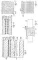
- Figure 1. Shows a top view partially in section of an opaque integrated thermophotovoltaic component according to the present invention.
- Figure 2. Shows a detail in section of figure 1.
- FIG. 3 Show partially in section more executive forms of opaque integrated thermophotovoltaic components according to the present invention.
- Figure 6. Shows a non-complete integrated transparent themophotovoltaic component.
- FIGS 7, 8.- Show partially in section more executive forms of integrated transparent themophotovoltaic components according to the present invention.
- Figure 9. Shows an enlarged section of an integrated transparent themophotovoltaic component.
- Figure 10.- Show an executive form which is an alternative of that shown in figure 9.
- FIGS 11, 12.- Show top views of executive forms of components according to figure 10.
- Figure 13.- Shows a view in lateral raising in section of a building with an installation enjoying the integrated thermophotovoltaic components according to the present invention.
- Figure 14.- Is a view in lengthways section of pseudo thermic transparent glass-glass according to the invention.
- Figure 15.- Is an analogous view of that of figure 13, illustrating in section a building with an installation enjoying the integrated thermophotovoltaic components according to a further executive form of the present invention.
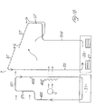
- Figure 16.- represents in a schematic mode the "summer" cycle of the installation of the building of figure 15.
- Figure 17.- represents in a schematic mode the "winter" cycle with supplementary heat contribution from a boiler of the "northern" side of the building of figure 15.
- Figure 18 Represents in a schematic mode the "winter" cycle of the building of figure 15, by means of the employment of the heat stored in the saline eutectic mixtures or polymeric materials of heat accumulation.
- thermophovoltaic component 1 an integrated thermophovoltaic component 1.
- the photo-voltaic cells which can also be of the traditional type, are connected in series and supply electricity to an electric circuit which is not shown.
- the photovoltaic cells 2 are placed on a metallic support 3 and covered with glass.
- the metallic support 3 is internally hollow and contains the channels 4.
- Such channels 4 are communicating with each other, in them is running a selective liquid preferably constituted by a glycol containing oxides and pigments with the characteristic of being transparent to the visible radiation and opaque to the infrared rays. Said selective liquid enters cool from the tube 5 and comes out hot from the tube 6.
- FIG 2 is shown the joining, by means of a welding between the component 1 and the tube 5.
- thermophotovoltaic component In figures 3, 4, 5 are illustrated diverse executive forms of opaque integrated thermophotovoltaic component, to equal parts correspond equal numeration. As it can be seen, the components illustrated are well connectable and compoundable with each other because the have lateral profiles which allow the noggnig of one component with the other. In the figures are shown only some possible solutions for the nogging.
- the photovoltaic cells 2 are inserted into the component, i.e. they are not in relief. Between two contiguous components can be created the narrow channel 7, into which can be inserted the threads of the electric circuit connected to the photovoltaic cells 2, as well as small tubes of an alternative hydraulic circuit.
- the lower profile of the integrated thermophotovoltaic component can have diverse types of alettes 8.
- the illustrated components can be placed both on the roofing of a building and inserted in its permetric walls.
- the alettes 8 allow so receiving or transferring heat to the walls by conduction, thus heating by convection and irradiation the internal cavities.
- the solar radiation is in part absorbed by the photovoltaic cells, in part by the selective liquid which is flowing in the channels 4, and in part is transferred by conduction to the walls of the building.
- the global temperature of the integrated thermophotovoltaic component is constantly maintained in the interior of the filed in which it has its maximum output.
- thermophotovoltaic transparent components In such components, the part 9 containing the channels 4 is of glass. The exchange is visible in figure 6.
- figures 7 and 8 are shown the sections of integrated thermophotovoltaic components 10 with profiles suitable to be embedded one into the contiguous one. To equal parts correspond equal numerations.
- the embedment is effected by means of opportune metal parts 11, 12. Also in this case is employed a small channel 7 for the electric cables and the small tubes.
- thermophotovoltaic components 10 are not constituted by traditional photovoltic cells, in the contrary case, their characteristic of transparence would be less seen.
- Figure 9 shows an executive form of an integrated thermophtovoltaic component in section.
- the parts 209 as it has already been said, are of glass and constitute the switch for the selective liquid 109.
- This selective liquid is of the known type, prevalently on the base of glycol.
- the surface 113 is a glass of the known type treated with S02, Ti02 or Ru02.
- the surface 213 is a conductive surface, the liquid 313 is an electrolytic solution.
- the part 413 is constituted by another glass, the surface 513 of which may not be plain, but machined in such a way that solar rays having different inclinations can be captured.
- the two faces of glass are peripherically welded together, letting between the same a microchamber containing the electrolyte.
- this may be preferably constituted by metallic threads 223 (figures 10, 11, 12) on the base of very conductive metals.
- Such threads which must be embedded in the thickness of the glass, can be recitularly arranged, on different planes, for instance, as shown in figures 11 and 12 to cover in an optimal way the whole surface of the integrated thermophotovoltaic component.
- thermophotovoltaic components 10 can constitute glass partitions of the building. Their function is quite analogous to that described in the case of opaque components. In this case, there is existing passage of light and heat by convection and irradiation from the integrated thermophotovoltaic component to the internal cavities.
- the photovoltaic part 13 of such components can also be placed on the metallic parts 3 of the opaque integrated thermophotovoltaic components instead of the traditional photovoltaic cells 2.
- thermophotovoltaic components described up to now can be utilised, beside for generating electric current or for any other type of use, also for a dynamical heating system, one executive form of which is shown in figure 13.
- a section of a building on the lateral walls of which are placed components 20, 21.
- the component 20 is turned westwards and the 21 eastwards. In the morning, only the component 21 is turned to the sun and, consequently, only this internal part of the building is now heated.
- the selective liquid which is circulating in the hydraulic circuit 22, impelled by the pump 23, with an opportune regulation of the valvular complexes 24, 25 only circulates in the right hand branch, since the left-hand one is not heated by the component 20 which, during the morning, is in the shadow.
- These selective hot liquid enters into the cistern 26 which is the lung of the heating installation.
- metallic elements 27 which contain materials, such as, for instance, eutectic saline mixtures, polymeric materials or other suitable materials having a low melting temperature, for instance, of the order of +18°C. Said elements 27 are closed in tight containers immerged in the selective liquid contained in the cistern 26 and remove the heat from said liquid.
- the cooled liquid is sent back to the component 21 of the pump 23.
- the heating circuit 28 If in the cavities turned westward (as northwards and southwards) the temperature is too lows, it will be compensated by the heating circuit 28. This is driven by a pump 29, the selection of the branches to be activated is effected by valvular complexes 30, 31 The selective liquid which circulates in the circuit 28 is heated in the cistern 26 thanks to the heat which is transferred to it by the elements 27 containing the polymeric and/or eutectic compounds. In the example treated, the selective liquid is made circulate only in the left side branch to heat the westward cavities through the thermic shields 32.
- Such thermic shields can be of the glass-glass type, otherwise of the glass-aluminium type, or even of the aluminium-aluminium type.
- a thermic shield 32 of the glass-glass type comprises, as indicated before, a glass plate 113' suitable treated with metallic oxides, thus to make it conductive on one surface, and an interstice made between two glass plates V in which flows the selective liquid 109, being the plate 113' and the interstice in which is flowing the selective liquid 109 in their turn separated by an interstice I in which is activated by means of (non-represented) suitable fans a forced air circulation.
- the effect of "thermic shield" of such a structure results evident.
- the plate 113' will not allow the passage of the ultraviolet rays, but letting pass instead the infrared ones, as well as those of the visible spectrum.
- the radiations of the infrared ones in their turn, will be absorbed by the selective liquid 109 circulating in the interstice between the glass plates V, whereas the radiations of the visible spectrum will pass without being disturbed also through the screen formed by the plates V and by the selective liquid circulating in them.
- the southern wall thanks to its position, has a greater function period and can allow the heating of all the rooms turned elsewhere.
- the northern wall instead only receives heat from the components arranged in all the other walls.
- the heating circuit 28 is not operating, in such a case the elements 27 of the cistern 26 are saturated, being their function secured for half quantities of energy; for this reason the valvular systems 24, 25 allow the selective fluid to enter into the circuit 33 impelled by the pump 35 to "accumulate" the heat in another container or cistern 34 installed underground, for instance.
- Such energy can be utilised by means of a heat exchanger to transfer it to other elements and use it when necessary.
- the walls can be substituted by integrated thermophotovoltaic components, which are transparent and opaque; these latter, deprived of the photovoltaic cells can be painted or plastered; for this reason, the whole outside surface of the building can be a surface which captures the sunbeams, making that the proper building is completely autonomous from the energetic point of view.
- an interstice I between the component 20 and the wall M of the building is foreseen an interstice I.
- Fans V procure a forced air circulation in said interstice I.
- said interstice is put in a position to communicate with the external ambient by means of the valves or shutters S, and with the internal ambient of the building by means of the valves or shutters S'. Consequently, when the heat in the components 20 results excessive because of an exposition to a particularly hot sun, for which reason the proper components 20 might not operate to the best of their yield, opening the valves S is determined an air flush towards the outside atmosphere which cools the components 20. On the contrary, if there is a need to increase the heating of the internal ambient of the building, opening the valves S' a hot air flush is introduced into the building.
- thermic screen of the northern side of the building and with ST the thermic screens of the southern side of the same building.
- the thermic screens ST are connected to each other by a circuit of fluid 200 in which is circulating the selective liquid contained in the cistern 26.
- the circulation is activated by the pump 201 and in two ends of the fluid circuit 200 are inserted, respectively above and below of said circuit, by-pass valves 202, 202' which communicate with said cistern 26 containing the eutectic elements 27.
- the thermic screens of the northern circuit of the building are in their turn connected to each other by a fluid circuit 400 making the head of a tank S1 with the interposition of by-pass valves 403.
- a circuitry branching of fluid 500 connects on one hand the by-pass valve 202 of the circuit 200 with the by-pass valve 403 of the circuit 400, and on the other hand the by-pass valve 403' of the circuit 400 with the by-pass valve 202' of the circuit 200, for the purposes which will be described here below.
- the circuit 300 comprises on the branches of inlet and outlet, two interception valves 304.
- Such a circuit makes the head on one hand of a sanitary water tank S, and on the other hand, by means of the by-pass valve 303, communicates with a radiating element 302, with the interposition of a circulation pump 301.
- the circuit 600 communicates by means of the interception valves 601, with the two ranches, of forward and return flow, of the circuit 400, below the by-pass valves 403 and 403'.
- the circuit 700 communicates, by means of the interception valves 701 with the two branches of forward and return flow of the circuit 200.
- the by-pass valves 202 and 202' put the circuit 200 in communication with the cistern 26, through which the heat captured by the thermic screens St will be carried by the selective liquid in it circulating in the cistern 26, and stored in the eutectic elements 27.
- the northern circuit 400 which in this condition is insulated from the circuits 200, transports the heat of the thermic screens ST to the cistern S which contains water.
- FIG 17 has been illustrated a winter condition in which, in order to increase the hear of the northern side of the building, the circuit 400, through the circuit 600, is connected to the boiler C, by means of opening of the valve 601, being closed the by-pass valves 403, 403'.
- FIG 18 is illustrated the "winter" condition of the installation of the whole building, with heating by means of the heat stored in the eutectic elements 27 contained in the cistern 26.
- the eutectic liquid is made circulate from the cistern 26 either through the circuit 200 or through the circuit 400, by means of the elements of the connection circuit 500.
- the valves 304 hot sanitary water will be supplied to the tank S and, in case of necessity, through the by-pass valves 303 and the pump 301 also to the radiating elements 301.
- the system according to the invention is constituted of a series of components, denominated thermic screens, the primary function of which is the capacity of recuperating 75% of the solar radiation and managing this energy as a bioblimatical regulator, equilibrating the external and internal thermal differences of the building through the walls or the glass partitions of perimetric tamponage.
- the thermic and photovoltaic shields are executed in several models, with employment of recyclable materials on the base of glasses, aluminium and polycarbonates.
- the components, with particular adaptations, can be integrated into the tamponage coverings and into the coatings of the buildings, enabling the substitution of traditional opaque or transparent materials, without compelling the projector to use specific architectural solutions.
- the external walls are no longer the unique barriers between the internal and the external climate, but they transform through the thermic shields fed by the solar energy into:
- the system associates a circulation of liquids and air, through the interstices of the thermic shield and therefore between the diverse walls and ambients obtaining a uniform internal microclimate, with a great energetic saving.
- a further advantage is the special form of "double-body sandwich" which allows the circulation of a selective liquid with the function of absorbing the radiation I.T. associated to a complete transparence to the visible which allows the passage of light to the interior of the lodging, being possible a control of the intensity of the same.
- a building projected with preferential orientation North-South will have a strong solar incidence on the facade exposed to the South, where will be originated an excess heating particularly during the summer months, in his case, the system with thermic shields will allow to take advantage of the thermic differential between the two facades for being able to compensate the temperatures through a regulating exchange and a chemical accumulation.
- the present invention controls the temperature of the photovoltic cells of any type with thermic exchange, cooling them or heating them, so as to maintain constant the coefficient of exercise on the aforementioned cells and therefore obtain the maximum electric output.
- the present invention is of course not limited to the executive forms illustrated and/or described, but it comprises all those executive variants and modifications entering in the ambit of the invention as claimed hereinafter.
Landscapes
- Engineering & Computer Science (AREA)
- Physics & Mathematics (AREA)
- Thermal Sciences (AREA)
- Chemical & Material Sciences (AREA)
- Combustion & Propulsion (AREA)
- Mechanical Engineering (AREA)
- General Engineering & Computer Science (AREA)
- Life Sciences & Earth Sciences (AREA)
- Sustainable Development (AREA)
- Sustainable Energy (AREA)
- Photovoltaic Devices (AREA)
- Laminated Bodies (AREA)
Applications Claiming Priority (2)
| Application Number | Priority Date | Filing Date | Title |
|---|---|---|---|
| ITGE980048 | 1998-06-10 | ||
| IT1998GE000048A IT1303609B1 (it) | 1998-06-10 | 1998-06-10 | Sistema dinamico termico-fotovoltaico. |
Publications (2)
| Publication Number | Publication Date |
|---|---|
| EP0971419A2 true EP0971419A2 (fr) | 2000-01-12 |
| EP0971419A3 EP0971419A3 (fr) | 2001-03-14 |
Family
ID=11355171
Family Applications (1)
| Application Number | Title | Priority Date | Filing Date |
|---|---|---|---|
| EP99500098A Withdrawn EP0971419A3 (fr) | 1998-06-10 | 1999-06-09 | Système thermovoltaque dynamique |
Country Status (2)
| Country | Link |
|---|---|
| EP (1) | EP0971419A3 (fr) |
| IT (1) | IT1303609B1 (fr) |
Cited By (11)
| Publication number | Priority date | Publication date | Assignee | Title |
|---|---|---|---|---|
| WO2005059963A1 (fr) * | 2003-12-16 | 2005-06-30 | Bp Corporation North America Inc. | Unite de montage de module photovoltaique et systeme correspondant |
| DE102006027629A1 (de) * | 2006-06-13 | 2007-12-27 | Willi Bihler | Solarelement mit Temperiereinrichtung |
| EP2012366A2 (fr) * | 2007-07-05 | 2009-01-07 | Federico Pirovano | Système photovoltaïque à efficacité améliorée et procédé incrémentiel de la production d'énergie électrique d'au moins un module solaire thermo-photovoltaïque |
| FR2924864A1 (fr) * | 2007-12-11 | 2009-06-12 | Photowatt Internat Soc Par Act | Module photovoltaique avec un echangeur thermique |
| EP2648233A1 (fr) * | 2012-04-04 | 2013-10-09 | Milboro Aktiengesellschaft | Élément de refroidissement pour l'agencement sur au moins une cellule solaire, agencement de plusieurs éléments de refroidissement et élément de module solaire |
| FR3036783A1 (fr) * | 2015-05-29 | 2016-12-02 | Systovi | Installation de panneaux photovoltaiques en sur-toiture |
| FR3036782A1 (fr) * | 2015-05-29 | 2016-12-02 | Systovi | Installation photovoltaique avec recuperation |
| WO2017029516A1 (fr) * | 2015-08-19 | 2017-02-23 | Hunter Alastair Gordon Laurence | Panneau de collecte de la chaleur ambiante |
| US11545932B2 (en) * | 2015-04-03 | 2023-01-03 | Dualsun | Photovoltaic and thermal solar panel |
| IT202300025068A1 (it) * | 2024-01-24 | 2025-07-24 | Antonio Caluisi | Pannello solar elettrico |
| DE102024113714A1 (de) * | 2024-05-16 | 2025-11-20 | MacroSolar SpA | Hybrides Solarmodul |
Family Cites Families (5)
| Publication number | Priority date | Publication date | Assignee | Title |
|---|---|---|---|---|
| US4180414A (en) * | 1978-07-10 | 1979-12-25 | Optical Coating Laboratory, Inc. | Concentrator solar cell array module |
| US4444992A (en) * | 1980-11-12 | 1984-04-24 | Massachusetts Institute Of Technology | Photovoltaic-thermal collectors |
| DE3419797A1 (de) * | 1984-05-26 | 1985-11-28 | Telefunken electronic GmbH, 7100 Heilbronn | Solar-energiewandler |
| IL96989A0 (en) * | 1991-01-21 | 1992-03-29 | Amitec Information Industry Lt | Multi-purpose solar energy conversion system |
| DE19851230A1 (de) * | 1998-11-06 | 1999-05-12 | Klaus Stein | Solar-Dach- und -Wandelement aus Metall |
-
1998
- 1998-06-10 IT IT1998GE000048A patent/IT1303609B1/it active IP Right Grant
-
1999
- 1999-06-09 EP EP99500098A patent/EP0971419A3/fr not_active Withdrawn
Cited By (15)
| Publication number | Priority date | Publication date | Assignee | Title |
|---|---|---|---|---|
| JP2007514088A (ja) * | 2003-12-16 | 2007-05-31 | ビーピー・コーポレーション・ノース・アメリカ・インコーポレーテッド | 光起電モジュール載置ユニット及びシステム |
| WO2005059963A1 (fr) * | 2003-12-16 | 2005-06-30 | Bp Corporation North America Inc. | Unite de montage de module photovoltaique et systeme correspondant |
| DE102006027629B4 (de) * | 2006-06-13 | 2013-10-17 | Willi Bihler | Solarelement mit Temperiereinrichtung, Verfahren zur Herstellung, Bausatz, Verwendung für eine Solarenergieanlage sowie Solarenergieanlage |
| DE102006027629A1 (de) * | 2006-06-13 | 2007-12-27 | Willi Bihler | Solarelement mit Temperiereinrichtung |
| US8307819B2 (en) | 2006-06-13 | 2012-11-13 | Willi Bihler | Solar element with temperature control device |
| EP2012366A2 (fr) * | 2007-07-05 | 2009-01-07 | Federico Pirovano | Système photovoltaïque à efficacité améliorée et procédé incrémentiel de la production d'énergie électrique d'au moins un module solaire thermo-photovoltaïque |
| FR2924864A1 (fr) * | 2007-12-11 | 2009-06-12 | Photowatt Internat Soc Par Act | Module photovoltaique avec un echangeur thermique |
| EP2648233A1 (fr) * | 2012-04-04 | 2013-10-09 | Milboro Aktiengesellschaft | Élément de refroidissement pour l'agencement sur au moins une cellule solaire, agencement de plusieurs éléments de refroidissement et élément de module solaire |
| WO2013150477A3 (fr) * | 2012-04-04 | 2014-01-30 | Milboro Aktiengesellschaft | Élément de refroidissement à monter sur au moins une cellule solaire, dispositif comportant plusieurs éléments de refroidissement et élément de module solaire |
| US11545932B2 (en) * | 2015-04-03 | 2023-01-03 | Dualsun | Photovoltaic and thermal solar panel |
| FR3036783A1 (fr) * | 2015-05-29 | 2016-12-02 | Systovi | Installation de panneaux photovoltaiques en sur-toiture |
| FR3036782A1 (fr) * | 2015-05-29 | 2016-12-02 | Systovi | Installation photovoltaique avec recuperation |
| WO2017029516A1 (fr) * | 2015-08-19 | 2017-02-23 | Hunter Alastair Gordon Laurence | Panneau de collecte de la chaleur ambiante |
| IT202300025068A1 (it) * | 2024-01-24 | 2025-07-24 | Antonio Caluisi | Pannello solar elettrico |
| DE102024113714A1 (de) * | 2024-05-16 | 2025-11-20 | MacroSolar SpA | Hybrides Solarmodul |
Also Published As
| Publication number | Publication date |
|---|---|
| ITGE980048A1 (it) | 1999-12-10 |
| EP0971419A3 (fr) | 2001-03-14 |
| ITGE980048A0 (it) | 1998-06-10 |
| IT1303609B1 (it) | 2000-11-15 |
Similar Documents
| Publication | Publication Date | Title |
|---|---|---|
| US4165036A (en) | Multi source heat pump air conditioning system | |
| KR100377069B1 (ko) | 태양광에너지변환장치및환기시스템 | |
| ES2648213T3 (es) | Soporte de techo con recolector solar estructuralmente integrado | |
| US20090223511A1 (en) | Unglazed photovoltaic and thermal apparatus and method | |
| US20100186734A1 (en) | Solar air heater for heating air flow | |
| CN101952667A (zh) | 具有至少一个热控制元件的建筑物的墙壁或屋顶 | |
| US20070056579A1 (en) | Energy Channeling Sun Shade System and Apparatus | |
| EP0971419A2 (fr) | Système thermovoltaque dynamique | |
| US6216688B1 (en) | Method for transparent heat insulation in building | |
| KR20110026394A (ko) | 태양광 전열 이용 시스템 | |
| US4290415A (en) | Building for cold districts | |
| RU2433359C2 (ru) | Теплонасосная система | |
| US4278075A (en) | Process and device for the recuperation of heat from selected ranges of the solar spectrum | |
| US4314544A (en) | Solar collector for a window frame | |
| Kaboré et al. | Parametric study of the thermal performance of a single-family house equipped with an airflow window integrating a heated glazing | |
| JP2012510604A (ja) | ソーラールーフィングアセンブリ | |
| KR101304860B1 (ko) | 발코니 및 건물외벽을 이용한 태양열 난방시스템 | |
| CN115033041A (zh) | 被动房环境调控系统及环境调控方法 | |
| SE509473C2 (sv) | Byggelement för värmeisolering, -isolering och/eller - reglering av byggnadshöljen | |
| KR102378280B1 (ko) | 외장재형 태양열 집열기 및 이의 시공방법 | |
| DE19614787A1 (de) | Gebäudeklimatisierungssystem mit Einrichtungen zur Konzentration von Sonnenstrahlung | |
| WO2008114247A1 (fr) | Panneau solaire | |
| US20180183380A1 (en) | Fluid-Cooled Blind Panels Configured to Generate Electricity and Heat | |
| GB2273151A (en) | "Solar energy transfer structual elements." | |
| DE9116975U1 (de) | Anlage zum Heizen und/oder Kühlen eines Gebäudes mit Solarenergie unter Verwendung von transparenter Wärmedämmung |
Legal Events
| Date | Code | Title | Description |
|---|---|---|---|
| PUAI | Public reference made under article 153(3) epc to a published international application that has entered the european phase |
Free format text: ORIGINAL CODE: 0009012 |
|
| 17P | Request for examination filed |
Effective date: 19990913 |
|
| AK | Designated contracting states |
Kind code of ref document: A2 Designated state(s): AT BE DE DK ES FR GB GR IE NL SE |
|
| AX | Request for extension of the european patent |
Free format text: AL;LT;LV;MK;RO;SI |
|
| RIC1 | Information provided on ipc code assigned before grant |
Free format text: 7H 01L 31/058 A, 7H 01L 31/052 B |
|
| PUAL | Search report despatched |
Free format text: ORIGINAL CODE: 0009013 |
|
| AK | Designated contracting states |
Kind code of ref document: A3 Designated state(s): AT BE CH CY DE DK ES FI FR GB GR IE IT LI LU MC NL PT SE |
|
| AX | Request for extension of the european patent |
Free format text: AL;LT;LV;MK;RO;SI |
|
| AKX | Designation fees paid |
Free format text: AT BE DE DK ES FR GB GR IE NL SE |
|
| RAP1 | Party data changed (applicant data changed or rights of an application transferred) |
Owner name: TRIMBOLI LONGUETO, ADRIANO |
|
| RIN1 | Information on inventor provided before grant (corrected) |
Inventor name: TRIMBOLI LONGUETO, ADRIANO |
|
| STAA | Information on the status of an ep patent application or granted ep patent |
Free format text: STATUS: THE APPLICATION IS DEEMED TO BE WITHDRAWN |
|
| 18D | Application deemed to be withdrawn |
Effective date: 20030103 |