EP0971438A1 - Verfahren zur Steuerung von Strahlungskeulen für die Kommunikation zwischen einer Basisstation und einem mobilem Funktelefon sowie zugehörige Basisstation - Google Patents
Verfahren zur Steuerung von Strahlungskeulen für die Kommunikation zwischen einer Basisstation und einem mobilem Funktelefon sowie zugehörige Basisstation Download PDFInfo
- Publication number
- EP0971438A1 EP0971438A1 EP99460042A EP99460042A EP0971438A1 EP 0971438 A1 EP0971438 A1 EP 0971438A1 EP 99460042 A EP99460042 A EP 99460042A EP 99460042 A EP99460042 A EP 99460042A EP 0971438 A1 EP0971438 A1 EP 0971438A1
- Authority
- EP
- European Patent Office
- Prior art keywords
- base station
- mobile
- antenna
- radiating elements
- reception
- Prior art date
- Legal status (The legal status is an assumption and is not a legal conclusion. Google has not performed a legal analysis and makes no representation as to the accuracy of the status listed.)
- Withdrawn
Links
Images

Classifications
-
- H—ELECTRICITY
- H04—ELECTRIC COMMUNICATION TECHNIQUE
- H04W—WIRELESS COMMUNICATION NETWORKS
- H04W16/00—Network planning, e.g. coverage or traffic planning tools; Network deployment, e.g. resource partitioning or cells structures
-
- H—ELECTRICITY
- H01—ELECTRIC ELEMENTS
- H01Q—ANTENNAS, i.e. RADIO AERIALS
- H01Q3/00—Arrangements for changing or varying the orientation or the shape of the directional pattern of the waves radiated from an antenna or antenna system
- H01Q3/26—Arrangements for changing or varying the orientation or the shape of the directional pattern of the waves radiated from an antenna or antenna system varying the relative phase or relative amplitude of energisation between two or more active radiating elements; varying the distribution of energy across a radiating aperture
- H01Q3/2605—Array of radiating elements provided with a feedback control over the element weights, e.g. adaptive arrays
-
- H—ELECTRICITY
- H04—ELECTRIC COMMUNICATION TECHNIQUE
- H04W—WIRELESS COMMUNICATION NETWORKS
- H04W16/00—Network planning, e.g. coverage or traffic planning tools; Network deployment, e.g. resource partitioning or cells structures
- H04W16/24—Cell structures
- H04W16/28—Cell structures using beam steering
Definitions
- the field of the invention is that of cellular digital radio communications using the technique of spatial multiplexing (or SDMA, for "Spatial Division Multiple Access”) in English).
- the invention therefore applies in particular, but not exclusively, to UMTS systems (for "Universal Mobile Telephone System - 2 GHz” in English), GSM 900 (for “Global System for Mobile - 900 Mhz” in English), DCS 1800 (for "Digital Cellular System - 1800 Mhz” in English), PCS 1900 (for "Personal Communication System - 1900 MHz” in English), etc.
- UMTS systems for "Universal Mobile Telephone System - 2 GHz” in English
- GSM 900 for “Global System for Mobile - 900 Mhz” in English
- DCS 1800 for "Digital Cellular System - 1800 Mhz” in English
- PCS 1900 for "Personal Communication System - 1900 MHz” in English
- the present invention relates to a method orientation of the radiating beam (s) radioelectric (s) for the communication between a base station and a mobile radiotelephone (sometimes also called mobile in the rest of this description).
- a digital radiocommunication system cellular includes a plurality of base stations, each providing radio coverage of a separate geographic unit capable of communicate with a plurality of mobile radio telephones present in this cell.
- the mobile radio is sometimes called mobile station, mobile phone, mobile terminal or terminal radiocommunication.
- the base station uses a radiating beam radio reception (and possibly a radiating beam radioelectric emission), directive (s) and electronically orientable (s) so as to "follow" the mobile radiotelephone when moving within the cell.
- the beam (s) of the same antenna is (are) oriented successively (for example during each interval of time) towards each of the mobiles whose communications are multiplexed.
- the base station Prior to monitoring the mobile radio, the base station must have identified the position of it, for example by an estimate of the direction of arrival of signals constituting a learning sequence emitted by the mobile radiotelephone (generally during the call initialization).
- the base station There are two types of beams that can be formed by the base station, namely the receiving beam, for the uplink of the communication (mobile radio to base station), and the beam transmission, for the downlink of the communication (base station to mobile radio).
- the base stations include smart beam-matching antennas (or "Adaptive Smart Antennas" in English), each including a network of radiating elements distributed matrically on a support (or panel).
- the network of radiating elements is composed of a plurality columns of radiating elements, each controlled independently of others and making it possible to form a beam according to a given azimuth.
- the base station controls the antenna so that it generates a directional radio beam, oriented in azimuth to a given mobile phone. In other words, the diagram of radiation from the antenna is pointed (or even focused) on the mobile radiotelephone in communication.
- each base station has a triangular configuration with three smart antennas (i.e. three networks of radiating elements) each covering a sector of 120 ° in azimuth.
- the SDMA technique does not work optimally because the smart antennas are controlled (by base stations) so that present selectivity only in azimuth. Because we don't traditionally considers that moving the mobile in a plane horizontal, just know the angular position of the mobile in this plane horizontal (i.e. the azimuth of the mobile in the horizontal plane containing the antenna panel) to be able to correctly orient the beam of the antenna towards the mobile. Consequently, since it is not currently never controlled, the vertical beam opening has a relatively large predetermined fixed value, so that the mobile can be followed by the antenna beam, regardless of its vertical position (i.e. whatever the angle of elevation of the mobile).
- the angle of mobile site is the angle formed by the line connecting the mobile to the antenna with the horizontal plane containing the antenna panel.
- the invention particularly aims to overcome these different disadvantages of the state of the art.
- one of the objectives of the present invention is to provide a method for orienting the radiating beam (s) radioelectric (s) for communication between a base station and a mobile radiotelephone, this method making it possible to improve the focusing of the or beams on the mobile radio.
- the invention also aims to provide such a method which, due to the improved focus of the beam (s), allows further improve system performance (increased gain of antennas, reduction of the transmission power of mobile radiotelephones and base stations, reduction of the number of sites, reduction of interference, reduction of minimum reuse angular distance same frequency, increased traffic capacity, better radio quality, ).
- a complementary objective of the invention is to provide such process which can be implemented without any material modification, with existing smart antennas and mobile radiotelephones existing.
- Another object of the invention is to provide a base station allowing the implementation of such a beam orientation method (x).
- the general principle of the invention therefore consists in focusing the (s) beam (x) in three dimensions and no longer in two dimensions.
- the beam (s) are pointed not only in azimuth (that is to say in the horizontal plane containing the antenna panel), but also on site (i.e. in the vertical plane containing the line connecting mobile on the air). In other words, we orient the beam (s) also up or down, depending on the vertical position of the mobile radiotelephone.
- This complementary selectivity according to the angle of site allows improve the focusing of the beam (s). Without prejudice as for the tracking of the mobile, it allows a strong reduction in the opening vertical of the beam (s) (x). As already explained above, such improving the focus of the beam (s) improves again the performance of the system (in terms of antenna gain, and / or transmission power of mobile radiotelephones and base stations, and / or number of sites, and / or interference, etc.).
- the information positioning parameter of angular orientation, in elevation and in azimuth, is used by the base station to orient the beam formed by the antenna.
- the positioning parameter of distance is used by the base station to calculate time advance information (or TA, for "Timing Advance” in English) specific to the mobile and allowing it to adjust to the time interval allocated to it, in the case of a time multiplexing (or TDMA).
- time advance information or TA, for "Timing Advance” in English
- said action on the reception parameters of the radiant elements consists in acting on the phase and the power of each radiant elements.
- each radiating element of the antenna network is associated with a torque (phase, amplitude) which can be represented in the form of a complex coefficient.
- a torque phase, amplitude
- the complementary selectivity according to the angle of elevation can be obtained by introducing a phase gradient along one and / or the other of the two alignment axes of the radiating elements. In this case, the beam tilts in the direction of the phase delay.
- the action on the reception parameters of the radiating elements is a function of at least one combination algorithm of signals.
- said at least one combination algorithm of signals belongs to the group comprising: the elimination algorithm interference; the signal maximization algorithm.
- each of said radiating elements has two orthogonal polarizations.
- said two orthogonal polarizations are two circular polarizations, straight and left respectively.
- said two orthogonal polarizations are two rectilinear polarizations, at + 45 ° and - 45 ° respectively.
- said steps for identifying the position of the mobile and orientation of the receiving beam are executed according to a iterative process.
- the beam "follows" the mobile in real time during its movement within the antenna coverage area (for example in a sector of a third of a cell, i.e. 120 ° in azimuth, in the case of a triangular base station configuration with three smart antennas).
- the learning sequence is for example transmitted by the mobile through a slow associated control channel (or SACCH, for "Slow Associated Control CHannel” in English).
- SACCH slow associated Control CHannel
- the antenna diagram can be adapted during and / or after the call establishment phase.
- the antenna is in this case used for reception and transmission, thanks to two separate beams, focused on the mobile. It's important to note that the action on the parameters (phase, amplitude) of the elements radiant is not the same in reception and in emission, in particular because that the frequencies are not the same on the uplink (mobile to base station) and downlink (base station to mobile).
- said action on the emission parameters of each of the radiating elements consists in using a set of parameters send selected from at least two sets of send parameters predetermined.
- the transmission parameters are not obtained by a complete independent calculation (which would be long and complex), but are deducted directly from the reception parameters calculated beforehand (and therefore a mobile positioning parameter previously identified).
- This deduction of the emission parameters to be used consists of a simple choice among several sets of possible emission parameters.
- said base station and said radiotelephone mobile are included in a cellular radio system belonging to the group comprising: UMTS systems; GSM systems 900; DCS 1800 systems and PCS 1900 systems.
- the invention also relates to a base station of a radiocommunication system, of the type comprising at least one antenna allowing the formation of radioelectric beam (s) for communication with a mobile radiotelephone, said antenna comprising a network of radiating elements distributed matrically on a support, said base station comprising means for orienting a reception beam formed by said antenna, as a function of an identification carried out beforehand, the orientation of said reception beam being carried out both in elevation and in azimuth, at by means of an action on the reception parameters of each of the radiating elements, differently from one another.
- a base station of a radiocommunication system of the type comprising at least one antenna allowing the formation of radioelectric beam (s) for communication with a mobile radiotelephone, said antenna comprising a network of radiating elements distributed matrically on a support, said base station comprising means for orienting a reception beam formed by said antenna, as a function of an identification carried out beforehand, the orientation of said reception beam being carried out both in elevation and in azimuth, at by means of an action
- said station basic further comprises means for orienting a beam emission formed by said antenna, according to said identification performed beforehand, the orientation of said emission beam being carried out at both in elevation and in azimuth, by means of an action on the parameters emission of each of the radiating elements, differently one by compared to each other.
- said base station comprises means for baseband processing, which are in the immediate vicinity of said network radiating elements of the antenna.
- each radiating element is connected, via separate amplification means, to said strip processing means of based.
- the invention therefore relates to a beam orientation method (x) radiating radioelectric (s) for communication between a radio station base and a mobile radio. More specifically, it is a process orientation of a reception beam, and possibly of a beam transmitter, formed by a smart antenna included in the transmission station base with which the mobile communicates.
- the present invention can be implemented whatever that is the number of intelligent antenna that the base station includes. Indeed, at all times, the base station communicates with the mobile via a single antenna.
- the antenna chosen by the base station to communicate with the mobile is the one that provides radio coverage in the area where the mobile.
- the base station may include three antennas sectored smart devices, each providing coverage over a sector of 120 ° in azimuth. Communication transfer management techniques intra-cellular (between two sectors of the same cell) are perfectly known to those skilled in the art and will therefore not be described in the present description. In the present description, by “antenna put in work in the process according to the invention ", it is therefore appropriate to hear either the single antenna of the base station, that which, among a plurality, provides radio coverage in the area where the mobile is located.
- the smart antenna includes a network of radiating elements (or independent transmitting / receiving modules) distributed matrically on a panel.
- the antenna is used reception and transmission, and therefore forms a reception beam and a emission beam. It is clear, however, that the invention applies also in the case where the antenna is used only for reception, and only forms a reception beam.
- UMTS is based on a FDD-WCDMA modulation (for "Frequency Division Duplex - Wide band Code Division Multiple Access "at 2 GHz.
- FDD-WCDMA modulation for "Frequency Division Duplex - Wide band Code Division Multiple Access "at 2 GHz.
- steps 1 to 3 are for example carried out according to a process iterative, so that the base station can follow the mobile in real time, when it moves within the geographic area covered by the antenna.
- Step 1 of identifying the position of the mobile consists of example to identify the angular orientation, in elevation and in azimuth, of the mobile phone to base station, as well as distance of the mobile radio relative to the base station.
- step 1 of identification of the position of the mobile can be based on the use of a sequence predetermined and known learning base station.
- the mobile radio starts with transmit (11) this learning sequence to the station based.
- the base station deduces (12) a direction of arrival, in elevation and in azimuth, from the signals of the learning sequence.
- a direction estimation algorithm destination such as MUSIC ("MUltiple SIgnal Classification"), ESPRIT ("Estimation of Signal Parameters via Rotational Invariance Techniques”), ML (“Maximum Likelihood”), WSF ("Weighted Subspace Fitting”), etc.
- step 1 of identification takes place by example during a call establishment phase.
- step 1 of identification each put in implements a learning sequence (distinct or not), so as to improve the estimated direction of arrival.
- step 1 of identification i.e. when the direction of arrival has been estimated at least once
- the signals emitted by the mobile during a call are used by the base (instead of the learning sequence) to modify dynamically estimating the direction of arrival of the signals emitted by the cellphone.
- Stage 2 of orientation, in elevation and in azimuth, of the reception beam is performed by means of an action on the reception parameters, such as the phase and the power, of each of the radiating elements, differently relative to each other.
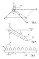
- Figure 3 shows an example of orientation of a radiotelephone mobile MS with respect to a smart antenna 41.
- the antenna 41 is at the center 0 of the reference frame (Ox, Oy, Oz).
- the MS mobile radio has a site angle ⁇ (measured relative to plane (Ox, Oy)) and an azimuth ⁇ (measured with respect to the direction Oz).
- Figure 4 shows a sectional view along the main axis of radiation 60, of an example of beam 61 obtained by the implementation of the method according to the invention.
- the angle between the main axis of radiation 60 and the plane (Ox, Oy) is the elevation angle ⁇ .
- this action on the parameters of reception depends on the direction of arrival on site and in azimuth.
- the determination of the values to be given to the reception parameters results from the execution of at least one combination algorithm signals, such as the interference elimination algorithm (or IRC, for "Interference Rejection Combining” in English) and the algorithm of signal maximization (or MRC, for "Maximum Ratio Combining” in English).
- the IRC aims to determine the complex weighting coefficients, that is to say the couples (phase, amplitude) of the radiating elements, so that the antenna diagram points the mobile in communication with the maximum gain, while canceling the diagram in the directions of interferers.
- the MRC which is the space diversity algorithm implemented in GSM, appears less efficient in the presence of interference. It is clear however that a combination of these two algorithms can be used, so as to combine their respective advantages.
- Stage 3 of orientation, in elevation and in azimuth, of the emission beam is carried out by means of an action on the emission parameters, such as the phase and power, of each of the radiating elements, differently one compared to each other.
- Each pre-programmed action can consist of a set of transmission parameters, stored in the base station. This is for example the estimated angular orientation, in elevation and in azimuth, during step 1 of identification which determines which pre-programmed action must be selected.
- This hundred distinct orientations of the emission beam for example amounts to covering a solid angle with an opening about 100 ° in azimuth and 60 ° in elevation ( ⁇ 30 ° from the horizontal plane containing the smart antenna).
- the emission parameters are deduced directly from the parameters reception.
- FIGS. 5 and 6 a mode particular embodiment of a base station according to the invention, allowing the implementation of the process discussed above (in relation to Figures 1 to 4).
- the station base 40 notably includes, in a conventional manner, (at least) an antenna intelligent 41 itself comprising a network of radiating elements 42 distributed matrically on a panel 43.
- the orientation of the reception beam, respectively transmission beam is carried out both in elevation and in azimuth by means of an action on the reception and transmission parameters respectively (i.e. phase and the amplitude) of each of the radiating elements 42, differently one by compared to each other.
- the orientation means 45, 46 comprise for example one or more digital signal processors (DSP).
- Each radiating element 42 has for example two orthogonal polarizations.
- each radiating element 42 includes for example a full disk with two connections (or points power supply) connected to a phase shifting network, so as to present a right / left circular polarization.
- each radiating element 42 has a double rectilinear polarization + 45 ° / -45 °.
- the antenna 41 includes a number of radiating elements 42 adapted at the desired focus.
- the precision is of the order of 10 ° ( ⁇ 5 °).
- the precision is of the order of 20 ° ( ⁇ 10 °) in azimuth and 20 ° ( ⁇ 10 °) on site.
- the removal of the secondary lobe by calculation is of the order of 15 dB.
- Figure 6 shows a simplified diagram of an embodiment particular wiring between them of different elements appearing on the figure 5. For the sake of simplification, a single row has been shown radiant elements 42.
- the baseband processing means 44 are placed at immediate proximity to the network of radiating elements 42. More specifically, each radiating element 42 is for example connected, via means 50 separate amplification means 44 for baseband processing. he it is possible to pass several carriers at 5 MHz. Furthermore, the power injected into each radiating element is for example of the order of Watt
- connection 51 has also been shown. baseband input / output.
- This connection 51 can be made, at choice, on copper pair (modem * DSL), on optical fiber in band base, ...
- the baseband processing means 44 ensure a double UMTS reception, for each of the radiating elements, consisting especially to demodulate the frequency RF intermediate, as well as an extraction of the received training sequence.
- the result of the baseband processing is transmitted, via connection 51, to the means 45 for orienting the reception beam.
Landscapes
- Engineering & Computer Science (AREA)
- Computer Networks & Wireless Communication (AREA)
- Signal Processing (AREA)
- Mobile Radio Communication Systems (AREA)
- Variable-Direction Aerials And Aerial Arrays (AREA)
- Radio Transmission System (AREA)
Applications Claiming Priority (2)
| Application Number | Priority Date | Filing Date | Title |
|---|---|---|---|
| FR9808782A FR2780817B1 (fr) | 1998-07-06 | 1998-07-06 | Procede d'orientation de faisceau(x) rayonnant(s) radioelectrique(s) pour la communication entre une station de base et un radiotelephone mobile, et station de base correspondante |
| FR9808782 | 1998-07-06 |
Publications (1)
| Publication Number | Publication Date |
|---|---|
| EP0971438A1 true EP0971438A1 (de) | 2000-01-12 |
Family
ID=9528447
Family Applications (1)
| Application Number | Title | Priority Date | Filing Date |
|---|---|---|---|
| EP99460042A Withdrawn EP0971438A1 (de) | 1998-07-06 | 1999-06-18 | Verfahren zur Steuerung von Strahlungskeulen für die Kommunikation zwischen einer Basisstation und einem mobilem Funktelefon sowie zugehörige Basisstation |
Country Status (3)
| Country | Link |
|---|---|
| EP (1) | EP0971438A1 (de) |
| JP (1) | JP2000059291A (de) |
| FR (1) | FR2780817B1 (de) |
Cited By (5)
| Publication number | Priority date | Publication date | Assignee | Title |
|---|---|---|---|---|
| AU741479B2 (en) * | 1997-09-04 | 2001-11-29 | Alcatel | Method of calibrating systems driving an array of active antennas |
| EP1124281A3 (de) * | 2000-02-10 | 2003-04-23 | Nec Corporation | Mit verschiedenen Algorithmen arbeitende adaptive Antennen |
| EP1287676A4 (de) * | 2000-05-16 | 2005-12-28 | Motorola Inc | Lokalisierung von durch antennen bereitgestellten kommunikationsdiensten |
| TWI565347B (zh) * | 2015-03-31 | 2017-01-01 | 佳世達科技股份有限公司 | 估算基站位置的方法 |
| WO2022182264A1 (en) * | 2021-02-24 | 2022-09-01 | Huawei Technologies Co., Ltd. | Wireless signal reflector and wireless communication method using the same |
Families Citing this family (5)
| Publication number | Priority date | Publication date | Assignee | Title |
|---|---|---|---|---|
| GB2367455A (en) * | 2000-09-29 | 2002-04-03 | Roke Manor Research | Interference reduction in a cellular communication system having a beamed downlink |
| EP1241906A3 (de) | 2001-02-14 | 2002-11-27 | NTT DoCoMo, Inc. | Kommunikationsregelungsverfahren und Vorrichtung in einem Mobilfunksystem |
| JP2004045042A (ja) * | 2002-07-08 | 2004-02-12 | Matsushita Electric Ind Co Ltd | 位置算出装置及び位置算出方法 |
| JP2012521120A (ja) * | 2009-03-20 | 2012-09-10 | テレフオンアクチーボラゲット エル エム エリクソン(パブル) | 改良型中継器 |
| WO2010110396A1 (ja) * | 2009-03-26 | 2010-09-30 | 京セラ株式会社 | アンテナ制御装置、無線通信システム及びアンテナ制御方法 |
Citations (7)
| Publication number | Priority date | Publication date | Assignee | Title |
|---|---|---|---|---|
| WO1995009490A1 (en) * | 1993-09-27 | 1995-04-06 | Telefonaktiebolaget Lm Ericsson | Using two classes of channels with different capacity |
| EP0715478A2 (de) * | 1994-11-28 | 1996-06-05 | Texas Instruments Inc. | Punkt-zu-Mehrpunkt-Kommunikationssystem mit geringer Leistung und Reichweite |
| EP0729285A2 (de) * | 1995-02-24 | 1996-08-28 | Alcatel SEL Aktiengesellschaft | Zuweisung einer Trägerfrequenz in einem SDMA-Funksystem |
| US5642353A (en) * | 1991-12-12 | 1997-06-24 | Arraycomm, Incorporated | Spatial division multiple access wireless communication systems |
| GB2309858A (en) * | 1996-01-31 | 1997-08-06 | Motorola Ltd | Channel Allocation in a Space Division Multiple Access Radio Communication System |
| EP0837523A2 (de) * | 1996-10-18 | 1998-04-22 | Kabushiki Kaisha Toshiba | Adaptive Antenne |
| EP0843380A2 (de) * | 1996-11-13 | 1998-05-20 | Sumitomo Electric Industries, Ltd. | Mobiles drahtloses Kommunikationssystem |
-
1998
- 1998-07-06 FR FR9808782A patent/FR2780817B1/fr not_active Expired - Lifetime
-
1999
- 1999-06-18 EP EP99460042A patent/EP0971438A1/de not_active Withdrawn
- 1999-07-06 JP JP11191255A patent/JP2000059291A/ja active Pending
Patent Citations (8)
| Publication number | Priority date | Publication date | Assignee | Title |
|---|---|---|---|---|
| US5642353A (en) * | 1991-12-12 | 1997-06-24 | Arraycomm, Incorporated | Spatial division multiple access wireless communication systems |
| WO1995009490A1 (en) * | 1993-09-27 | 1995-04-06 | Telefonaktiebolaget Lm Ericsson | Using two classes of channels with different capacity |
| EP0715478A2 (de) * | 1994-11-28 | 1996-06-05 | Texas Instruments Inc. | Punkt-zu-Mehrpunkt-Kommunikationssystem mit geringer Leistung und Reichweite |
| EP0729285A2 (de) * | 1995-02-24 | 1996-08-28 | Alcatel SEL Aktiengesellschaft | Zuweisung einer Trägerfrequenz in einem SDMA-Funksystem |
| US5732075A (en) * | 1995-02-24 | 1998-03-24 | Alcatel N.V. | Assignment of a carrier frequency in an SDMA radio system |
| GB2309858A (en) * | 1996-01-31 | 1997-08-06 | Motorola Ltd | Channel Allocation in a Space Division Multiple Access Radio Communication System |
| EP0837523A2 (de) * | 1996-10-18 | 1998-04-22 | Kabushiki Kaisha Toshiba | Adaptive Antenne |
| EP0843380A2 (de) * | 1996-11-13 | 1998-05-20 | Sumitomo Electric Industries, Ltd. | Mobiles drahtloses Kommunikationssystem |
Non-Patent Citations (1)
| Title |
|---|
| BACHMAN H L: "SMART ANTENNAS - THE PRACTICAL REALITIES", ANNUAL REVIEW OF COMMUNICATIONS, vol. 50, 1997, pages 1011 - 1015, XP000720968 * |
Cited By (5)
| Publication number | Priority date | Publication date | Assignee | Title |
|---|---|---|---|---|
| AU741479B2 (en) * | 1997-09-04 | 2001-11-29 | Alcatel | Method of calibrating systems driving an array of active antennas |
| EP1124281A3 (de) * | 2000-02-10 | 2003-04-23 | Nec Corporation | Mit verschiedenen Algorithmen arbeitende adaptive Antennen |
| EP1287676A4 (de) * | 2000-05-16 | 2005-12-28 | Motorola Inc | Lokalisierung von durch antennen bereitgestellten kommunikationsdiensten |
| TWI565347B (zh) * | 2015-03-31 | 2017-01-01 | 佳世達科技股份有限公司 | 估算基站位置的方法 |
| WO2022182264A1 (en) * | 2021-02-24 | 2022-09-01 | Huawei Technologies Co., Ltd. | Wireless signal reflector and wireless communication method using the same |
Also Published As
| Publication number | Publication date |
|---|---|
| FR2780817B1 (fr) | 2007-09-14 |
| JP2000059291A (ja) | 2000-02-25 |
| FR2780817A1 (fr) | 2000-01-07 |
Similar Documents
| Publication | Publication Date | Title |
|---|---|---|
| JP4121560B2 (ja) | 方向性無線通信方法及び装置 | |
| JP4457120B2 (ja) | 広角度アンテナローブ | |
| CA2172672C (fr) | Procede de reception multicapteur d'une station de base fixe d'un reseau de communication echangeant des donnees avec des mobiles, et dispositif pour sa mise en oeuvre | |
| EP1255362B1 (de) | Verfahren und Vorrichtung zum Empfang eines Signals | |
| CA2272930C (en) | Cochannel signal processing system | |
| Stevanovic et al. | Smart antenna systems for mobile communications | |
| US20040033818A1 (en) | Mobile communication device | |
| EP0960451A1 (de) | Verfahren und vorrichtung zur richtfunkübertragung | |
| NZ274026A (en) | Cellular telecommunication: transmitting channels in wide lobe then narrow lobe when mobile position is determined | |
| KR20050117436A (ko) | 공간-시간 빔 형성을 위한 간섭전력 측정 장치 및 방법 | |
| KR20020013813A (ko) | 무선 데이터 어플리케이션들을 위한 적응성 안테나 방식에기초한 위치 확인 | |
| JP2000509944A (ja) | 方向性無線通信方法及び装置 | |
| CN106954223A (zh) | 一种动中通端站系统及动中通端站系统的通信方法 | |
| JPH10501395A (ja) | アンテナ用ダイバシティ結合 | |
| FR2780817A1 (fr) | Procede d'orientation de faisceau(x) rayonnant(s) radioelectrique(s) pour la communication entre une station de base et un radiotelephone mobile, et station de base correspondante | |
| EP3952138B1 (de) | Verfahren für den zugang zu einem satellitennetz durch beam-hopping | |
| FR2861231A1 (fr) | Methode de communication dans un reseau de communication sans fil | |
| EP1016162B1 (de) | Verfahren zur kommunikation zwischen einer basisstation mit n-antennen und einem mobilen telefon und basisstation zur durchführung des verfahrens | |
| CN206790714U (zh) | 一种动中通端站系统 | |
| CA3049772A1 (en) | Real time adaptation of a mobile repeater antenna pattern | |
| EP1000445B1 (de) | Gruppenantenne für basisstation zur funkverbindung mit mobilen teilnehmern | |
| EP0982960B1 (de) | Funkkommunikationsnetz Testverfahren und entsprechende Vorrichtung und Basisstation | |
| FR2805119A1 (fr) | Procede de repartition des communications au sein d'une cellule d'un reseau de radiocommunication, dispositif et station de base correspondants | |
| EP0971486A1 (de) | Mobiles Funkendgerät mit wenigstens zwei Antennen mit Polarisationsdiversity zum Empfang von Signalen | |
| EP3506527B1 (de) | Steuerungsverfahren eines kommunikationsnetzes, und entsprechendes kommunikationsnetz |
Legal Events
| Date | Code | Title | Description |
|---|---|---|---|
| PUAI | Public reference made under article 153(3) epc to a published international application that has entered the european phase |
Free format text: ORIGINAL CODE: 0009012 |
|
| AK | Designated contracting states |
Kind code of ref document: A1 Designated state(s): AT BE CH CY DE DK ES FI FR GB GR IE IT LI LU MC NL PT SE |
|
| AX | Request for extension of the european patent |
Free format text: AL;LT;LV;MK;RO;SI |
|
| 17P | Request for examination filed |
Effective date: 20000215 |
|
| AKX | Designation fees paid |
Free format text: AT BE CH CY DE DK ES FI FR GB GR IE IT LI LU MC NL PT SE |
|
| 17Q | First examination report despatched |
Effective date: 20040121 |
|
| RAP1 | Party data changed (applicant data changed or rights of an application transferred) |
Owner name: COMPAGNIE FINANCIERE POUR LE RADIOTELEPHONE SA |
|
| RAP1 | Party data changed (applicant data changed or rights of an application transferred) |
Owner name: CEGETEL GROUPE |
|
| RAP1 | Party data changed (applicant data changed or rights of an application transferred) |
Owner name: SOCIETE FRANEAISE DU RADIOTELEPHONE-SFR |
|
| STAA | Information on the status of an ep patent application or granted ep patent |
Free format text: STATUS: THE APPLICATION IS DEEMED TO BE WITHDRAWN |
|
| 18D | Application deemed to be withdrawn |
Effective date: 20040602 |
|
| REG | Reference to a national code |
Ref country code: HK Ref legal event code: WD Ref document number: 1025187 Country of ref document: HK |