EP0971456A2 - Verrouillage positif de connecteur - Google Patents
Verrouillage positif de connecteur Download PDFInfo
- Publication number
- EP0971456A2 EP0971456A2 EP99113271A EP99113271A EP0971456A2 EP 0971456 A2 EP0971456 A2 EP 0971456A2 EP 99113271 A EP99113271 A EP 99113271A EP 99113271 A EP99113271 A EP 99113271A EP 0971456 A2 EP0971456 A2 EP 0971456A2
- Authority
- EP
- European Patent Office
- Prior art keywords
- connector
- ramp
- latch
- axis
- latch groove
- Prior art date
- Legal status (The legal status is an assumption and is not a legal conclusion. Google has not performed a legal analysis and makes no representation as to the accuracy of the status listed.)
- Granted
Links
- 230000002093 peripheral effect Effects 0.000 claims description 8
- 229920001971 elastomer Polymers 0.000 claims description 4
- 239000000806 elastomer Substances 0.000 claims description 3
- 230000013011 mating Effects 0.000 abstract description 3
- 230000000007 visual effect Effects 0.000 description 2
- 230000000694 effects Effects 0.000 description 1
- 229920001821 foam rubber Polymers 0.000 description 1
- 239000000463 material Substances 0.000 description 1
Images


Classifications
-
- H—ELECTRICITY
- H01—ELECTRIC ELEMENTS
- H01R—ELECTRICALLY-CONDUCTIVE CONNECTIONS; STRUCTURAL ASSOCIATIONS OF A PLURALITY OF MUTUALLY-INSULATED ELECTRICAL CONNECTING ELEMENTS; COUPLING DEVICES; CURRENT COLLECTORS
- H01R13/00—Details of coupling devices of the kinds covered by groups H01R12/70 or H01R24/00 - H01R33/00
- H01R13/62—Means for facilitating engagement or disengagement of coupling parts or for holding them in engagement
- H01R13/627—Snap or like fastening
-
- H—ELECTRICITY
- H01—ELECTRIC ELEMENTS
- H01R—ELECTRICALLY-CONDUCTIVE CONNECTIONS; STRUCTURAL ASSOCIATIONS OF A PLURALITY OF MUTUALLY-INSULATED ELECTRICAL CONNECTING ELEMENTS; COUPLING DEVICES; CURRENT COLLECTORS
- H01R13/00—Details of coupling devices of the kinds covered by groups H01R12/70 or H01R24/00 - H01R33/00
- H01R13/62—Means for facilitating engagement or disengagement of coupling parts or for holding them in engagement
- H01R13/629—Additional means for facilitating engagement or disengagement of coupling parts, e.g. aligning or guiding means, levers, gas pressure electrical locking indicators, manufacturing tolerances
- H01R13/633—Additional means for facilitating engagement or disengagement of coupling parts, e.g. aligning or guiding means, levers, gas pressure electrical locking indicators, manufacturing tolerances for disengagement only
-
- H—ELECTRICITY
- H01—ELECTRIC ELEMENTS
- H01R—ELECTRICALLY-CONDUCTIVE CONNECTIONS; STRUCTURAL ASSOCIATIONS OF A PLURALITY OF MUTUALLY-INSULATED ELECTRICAL CONNECTING ELEMENTS; COUPLING DEVICES; CURRENT COLLECTORS
- H01R13/00—Details of coupling devices of the kinds covered by groups H01R12/70 or H01R24/00 - H01R33/00
- H01R13/62—Means for facilitating engagement or disengagement of coupling parts or for holding them in engagement
- H01R13/627—Snap or like fastening
- H01R13/6271—Latching means integral with the housing
- H01R13/6273—Latching means integral with the housing comprising two latching arms
-
- H—ELECTRICITY
- H01—ELECTRIC ELEMENTS
- H01R—ELECTRICALLY-CONDUCTIVE CONNECTIONS; STRUCTURAL ASSOCIATIONS OF A PLURALITY OF MUTUALLY-INSULATED ELECTRICAL CONNECTING ELEMENTS; COUPLING DEVICES; CURRENT COLLECTORS
- H01R2101/00—One pole
Definitions
- the present invention relates to a positive latch connector. More particularly, the present invention relates to a positive latch connector for use with electrical connectors such as those used, for example, with an antenna connector.
- Typical electrical connectors such as, for example those used with an antenna connector for an antenna cable such as that used in the automobile industry for radios, include a male connector body generally in the form of a plug and a female connector body generally in the form of a ferrule which forms a socket. In use, the male connector body is plugged into the female connector body to effect a mechanical and electrical connection between the two.
- an antenna cable in the form of a coaxial cable is electrically and mechanically attached to one of the connectors such as the male connector, and the other connector, such as the female connector, is electrically and mechanically attached to a circuit such as a circuit on a printed circuit board.
- Yet another object of the present invention is to provide a positive latch connector which prevents inadvertent disconnection thereof.
- a further object of the present invention is to provide an electrical connector which includes the positive latch connector of the present invention.
- Another object of the present invention is to provide such an electrical connector for use as an antenna connector.
- Yet another object of the invention is the enhancement of electrical connectors.
- a positive latch connector which comprises a first connector body extending in the direction of a first axis and a second connector body extending in the direction of a second axis.
- the first connector body comprises at least one first connector which comprises a first and second latch groove, a first, second and third ramp and an elastic member.
- the first latch groove extends into an outer surface of the first connector body to a first base and is positioned between a first end and a second end of the first connector body.
- the second latch groove extends into such outer surface to a second base and is positioned between the first latch groove and the second end of the first connector body.
- Each second connector comprises a beam which comprises a pin which (a) engages the first ramp in a connecting mode, (b) compresses the elastic member and engages the first latch groove in a connected mode, and (c) further compresses the elastic member and sequentially engages the second ramp, the second latch groove and the third ramp in a disconnecting mode.
- Fig. 1 depicts a positive latch connector 10 which includes a first connector body 12 which extends in the direction 14, 14' of a longitudinal axis 16 of the first connector body, and a second connector body 18 which extends in the direction 20, 20' of a longitudinal axis 22 of the second connector body.
- first connector body 12 When the first connector body 12 is connected to the second connector body 18, axes 16 and 22 will be coincident as depicted in Fig. 1.
- the first connector body 12 and the second connector body 18 are each cylindrical.
- the first connector body comprises at least one connector.
- the first connector body 12 includes two connectors 24, although more or less connectors 24 may be provided.
- Each connector 24 includes a first latch groove 26, a second latch groove 28, a first ramp 30, a second ramp 32 and a third tramp 34.
- An elastic member 36 (not shown in Fig. 1) is also provided.
- the elastic member 36 is positioned between the latch groove 26 and the latch groove 28.
- the elastic member 36 is fabricated from an elastomer, rubber or the like material, such as foam rubber.
- Each latch groove 26 extends into an outer peripheral surface 38 of the first connector body 12 and is spaced from an end 40 of the first connector body in the direction 14 of axis 16.
- Latch groove 26 includes a base 42 which is disposed below outer peripheral surfaces 38. Latch groove 26 is positioned between the first end 40 of the first connector body 12 and a second end 44 thereof.
- the second latch groove 28 extends into outer peripheral surface 38 to a second base 46 which is disposed below surface 38.
- the latch groove 28 is positioned between the latch groove 26 and the end 44 of the first connector body 12.
- the second connector body comprises at least one connector.
- the second connector body 18 includes two connectors 48 although more of less connectors 48 may be provided.
- Each connector 48 includes a beam 50.
- beam 50 is in the form of a flexible segment which extends in the direction of axis 22 from a proximate end 52 to a distal end 54.
- a pin 56 protrudes from the distal end 54 towards axis 22.
- each pin 56 (a) engages a ramp 30 in a connecting mode, (b) compresses the elastic member 36 and engages a latch groove 26 in a connected mode, and (c) further compresses the elastic member and sequentially engages a ramp 32, a groove 28 and a ramp 34 in a disconnecting mode, as described herein.
- the two connectors 24 form a pair of connectors which are spaced from each other about 180° in a circumferential direction 58, 58' relative to axis 16.
- the two connectors 48 are spaced from each other about 180° in a circumferential direction 60, 60' relative to axis 22 so that they may be aligned with respective connectors 24, as described herein.
- One or more additional pair of identical connectors 24, and one or more additional pair of identical connectors 48 may be provided, if desired.
- the spacing in the circumferential directions 58, 58' for the connectors 24, and in the circumferential direction 60, 60' for the connectors 48, will be such that respective connectors 24, will be in alignment with respective connectors 48, during use.
- the two connectors 24 and the ramps and latch grooves of each, are spaced from each other about 180° in direction 58, 58'.
- Figs. 1 to 4 the embodiment illustrated in Figs. 1 to 4 and the diagrammatic plan view thereof illustrated in Fig. 5.
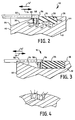
- the elastic member 36 may be, for example, an elastomeric block which has been wedged as illustrated in Fig. 2 between the surface 70 of the latch groove 26 and the surface 70' of the latch groove 28, Fig. 5 merely illustrates a portion of that surface of the elastic member 36 which the end 54 of segment 50 engages to compress the elastic member as the first connector body 12 and second connector body 14 are connected together.
- a positive latch connector is illustrated which comprises two connectors 24 and two corresponding connectors 48. It will be apparent to those skilled in the art that the following description is also applicable to embodiments having more or less than two such connectors.
- the connector body 18 is first oriented relative to the connector body 12 such that axes 16 and 22 are coincident and pins 56 are in axial alignment with respective ramps 30.
- Connectors 12 and 18 may then be moved relative to each other in directions 14', 20 causing pins 56 to engage respective ramps 30 in a connecting mode.
- By dimensioning the connectors such that the distance 62 between the tips of the pins 56 is about equal to or only slightly greater than the distance 64 between edges 66 of ramps 30, such movement will cause ramps 30 to serve as cam surfaces for pins 56 to urge flexible segments 50 away from each other until the pins reach edges 68 of ramps 30.
- edge 66 is a greater distance below outer peripheral surface 38 than is edge 68.
- a pin 56 first engages and slides upon ramp 30 in direction 14.
- pin 56 engages the elastic member 36 and begins to compress it.
- pin 56 has sufficiently compressed the elastic member 36 so that the resiliency of the flexible segments 50 causes the pin to snap into latch groove 26 and the resilience of the elastic member 36 urges the pin in direction 14' against the wall 70.
- the user When it is desired to disconnect the positive latch connector 10, the user exerts a force upon the first connector body 12 in direction 14. The user must apply sufficient force to overcome the increasing resistance presented in the direction 14' by the elastic members 36, to cause the elastic members to be further compressed and the pins 56 to slide up the ramps 32. In this manner, the elastic members prevent inadvertent disconnection of the device. As the pins 56 slide beyond the edge 78 of ramp 32, the resilience of the flexible segments 50 cause the pins 56 to snap into the latch grooves 28 and engage bases 46. Although not necessary, edge 78 is disposed below edge 68 as illustrated in Fig. 2.
- each elastic member 36 urges the first connector body 12 in direction 14' causing the pins 56 to slide from bases 46 to the ramps 34.
- the resiliency in the elastic member will continue to urge the first connector body 12 in direction 14' causing 56 to slide up ramps 34 until the elastic member is fully decompressed and assumes its original position adjacent edge 68. In this manner, the resiliency of each elastic member 36 facilitates disconnection.
- the user can then completely remove the first connector body 12 from the second connector body 18 by pulling the first connector body in direction 14'.
- Such disconnecting movement is diagrammatically illustrated in Fig. 5.
- the force applied by the user in direction 14 has overcome the resistance of the elastic member 36 and allowed the pin 56 to slide up ramp 32 and sufficiently compress the elastic member 36 so that the resiliency of the flexible segments 50 causes the pin 56 to snap into latch groove 28.
- the resiliency of the elastic member urges the second connector body 18 in direction 14' as the pin slides from base 46 up ramp 34.
- the base 42 of latch groove 26 is adjacent ramps 30 and 32, and the base 46 of latch groove 28 is adjacent ramp 32 and ramp 34.
- a wall 86 may be provided. Wall 86 extends in the direction of axis 16 between the ramp 30 and latch groove 26, on the one hand, and the ramp 34, on the other.
- ramp 32 may comprise a triangularly configured ramp surface as illustrated in Fig. 6.
- such triangularly configured ramp surface includes a first edge 88 which is coextensive with an edge of base 42 and extends from a first point 90 at wall 86 to an opposite second point 92.
- a second edge 94 is substantially perpendicular to the first edge 88 and extends from point 92 to an opposite third point 96.
- the third edge 98 of the triangularly configured ramp surface extends from the first point 90 to the third point 96. It will be readily apparent from Fig. 6 that such triangularly configured ramp surface will not only facilitate movement of the pins 56 from the latch groove 28 but will facilitate movement of the pin 56 towards the ramp 34.
- each base 46 may include a first surface 100 adjacent the ramp 32, and a second surface 102 adjacent the ramp 34, the surface 100 being joined to the surface 102 by a third surface 104.
- the surface 104 extends at an angle from surface 100 to surface 102 to further facilitate movement of pin 56.
- Movement of pin 56 from base 46 to the ramp 34 may be further facilitated by modifying one end of wall 86 to provide a beveled surface.
- wall 86 extends from an end 106 adjacent the end 40 of the first connector body 12 to an end 108 adjacent the junction between the latch groove 26 and the ramp 32.
- End 108 of the wall 86 may include a beveled edge or surface 110 so that end 108 does not impede movement of the pin 56.
- the third edge 98 of the triangularly configured ramp surface 32 may extend along an axis 112, and beveled surface 110 may extend along axis 112.
- the connector bodies 12 and 18 may be in the form of cylindrical sleeves as depicted in Fig. 1. Such sleeves include bores 114 and 116 which extend completely through connector bodies 12 and 18, respectively.
- An electrical male antenna connector 118 may be positioned in bore 116, and a mating electrical female antenna connector 120 may be positioned in bore 114, in a conventional manner.
- male connector 118 will extend into the female connector 120 in the usual manner to provide the desired electrical connection between the two.
- the connector bodies 12 and 18 When in the connected mode, the connector bodies 12 and 18 will be mechanically locked to each other as a result of the abutment of each pin 56 with a respective wall 70 as described herein. In this manner, the electrical connection between electrical connectors 118 and 120 will not be unintentionally disconnected; that is, electrical connection will be assured until the connector bodies 12 and 18 are disconnected.
Landscapes
- Details Of Connecting Devices For Male And Female Coupling (AREA)
Applications Claiming Priority (2)
| Application Number | Priority Date | Filing Date | Title |
|---|---|---|---|
| US111670 | 1998-07-08 | ||
| US09/111,670 US5993239A (en) | 1998-07-08 | 1998-07-08 | Positive latch connector |
Publications (3)
| Publication Number | Publication Date |
|---|---|
| EP0971456A2 true EP0971456A2 (fr) | 2000-01-12 |
| EP0971456A3 EP0971456A3 (fr) | 2002-08-21 |
| EP0971456B1 EP0971456B1 (fr) | 2004-03-24 |
Family
ID=22339822
Family Applications (1)
| Application Number | Title | Priority Date | Filing Date |
|---|---|---|---|
| EP99113271A Expired - Lifetime EP0971456B1 (fr) | 1998-07-08 | 1999-07-08 | Verrouillage positif de connecteur |
Country Status (5)
| Country | Link |
|---|---|
| US (1) | US5993239A (fr) |
| EP (1) | EP0971456B1 (fr) |
| KR (1) | KR100573970B1 (fr) |
| CA (1) | CA2273812A1 (fr) |
| DE (1) | DE69915738T2 (fr) |
Cited By (4)
| Publication number | Priority date | Publication date | Assignee | Title |
|---|---|---|---|---|
| EP1901402A1 (fr) * | 2006-09-16 | 2008-03-19 | Hirschmann Automation and Control Gmbh | Connecteur solaire doté de moyens d'encliquetage améliorés |
| WO2009131613A1 (fr) | 2008-04-25 | 2009-10-29 | Casco Products Corporation | Mécanisme de verrouillage |
| WO2010127065A1 (fr) * | 2009-04-30 | 2010-11-04 | Corning Gilbert Inc. | Connecteur faible resistance pour carte de circuit imprime |
| CN103682781A (zh) * | 2012-09-06 | 2014-03-26 | 广濑电机株式会社 | 电连接器组装体 |
Families Citing this family (9)
| Publication number | Priority date | Publication date | Assignee | Title |
|---|---|---|---|---|
| JP3077696B1 (ja) * | 1999-08-17 | 2000-08-14 | 住友電装株式会社 | コネクタ |
| JP4711808B2 (ja) * | 2005-11-25 | 2011-06-29 | 日本圧着端子製造株式会社 | コネクタ |
| US20080057767A1 (en) | 2006-08-10 | 2008-03-06 | O'rourke Kevin | Electrical adaptor having an anchor |
| US7611372B2 (en) * | 2007-05-31 | 2009-11-03 | Cooper Technologies Company | Rotatably locking plug and connector |
| US7726999B2 (en) * | 2007-12-21 | 2010-06-01 | Van-System S.R.L. | Electrical connector set |
| US7686660B2 (en) | 2008-04-10 | 2010-03-30 | Osram Sylvania Inc. | Connector and receptacle therefor |
| DE202011107618U1 (de) * | 2011-10-01 | 2013-01-03 | Brose Fahrzeugteile Gmbh & Co. Kommanditgesellschaft, Hallstadt | Steckverbindung zum Herstellen einer elektrischen Verbindung |
| DE102019114257B4 (de) * | 2019-05-28 | 2021-01-21 | Amphenol Tuchel Industrial GmbH | Steckverbinder mit Verriegelungssystem |
| US11594847B2 (en) | 2020-04-30 | 2023-02-28 | Kevin O'Rourke | Wireless monitoring of electrical connector |
Family Cites Families (6)
| Publication number | Priority date | Publication date | Assignee | Title |
|---|---|---|---|---|
| US3252124A (en) * | 1961-03-10 | 1966-05-17 | Wago Klemmenwerk G M B H | Push-in connector |
| US3184703A (en) * | 1962-11-02 | 1965-05-18 | Gen Dynamics Corp | Multiple wire control cable connector |
| US4211461A (en) * | 1978-11-27 | 1980-07-08 | Industrial Electronic Hardware Corp. | Axially mating cable connector |
| US5131862A (en) * | 1991-03-01 | 1992-07-21 | Mikhail Gershfeld | Coaxial cable connector ring |
| JP2613998B2 (ja) * | 1992-07-10 | 1997-05-28 | 矢崎総業株式会社 | 低挿入力コネクタの嵌合構造 |
| US5599199A (en) * | 1995-05-10 | 1997-02-04 | Osram Sylvania Inc. | Positive latch connector |
-
1998
- 1998-07-08 US US09/111,670 patent/US5993239A/en not_active Expired - Fee Related
-
1999
- 1999-06-08 CA CA002273812A patent/CA2273812A1/fr not_active Abandoned
- 1999-07-07 KR KR1019990027175A patent/KR100573970B1/ko not_active Expired - Fee Related
- 1999-07-08 DE DE69915738T patent/DE69915738T2/de not_active Expired - Fee Related
- 1999-07-08 EP EP99113271A patent/EP0971456B1/fr not_active Expired - Lifetime
Cited By (10)
| Publication number | Priority date | Publication date | Assignee | Title |
|---|---|---|---|---|
| EP1901402A1 (fr) * | 2006-09-16 | 2008-03-19 | Hirschmann Automation and Control Gmbh | Connecteur solaire doté de moyens d'encliquetage améliorés |
| WO2009131613A1 (fr) | 2008-04-25 | 2009-10-29 | Casco Products Corporation | Mécanisme de verrouillage |
| EP2272137A4 (fr) * | 2008-04-25 | 2011-09-07 | Casco Products Corp | Mecanisme de verrouillage |
| WO2010127065A1 (fr) * | 2009-04-30 | 2010-11-04 | Corning Gilbert Inc. | Connecteur faible resistance pour carte de circuit imprime |
| CN102498619A (zh) * | 2009-04-30 | 2012-06-13 | 康宁电磁股份有限公司 | 用于印刷电路板的低阻力连接器 |
| CN102498619B (zh) * | 2009-04-30 | 2015-01-28 | 康宁电磁股份有限公司 | 用于印刷电路板的低阻力连接器 |
| CN103682781A (zh) * | 2012-09-06 | 2014-03-26 | 广濑电机株式会社 | 电连接器组装体 |
| EP2706622A3 (fr) * | 2012-09-06 | 2014-10-01 | Hirose Electric Co., Ltd. | Composant assemblé de connecteur électrique |
| US9054452B2 (en) | 2012-09-06 | 2015-06-09 | Hirose Electric Co., Ltd. | Electrical connector assembled component |
| CN103682781B (zh) * | 2012-09-06 | 2016-10-26 | 广濑电机株式会社 | 电连接器组装体 |
Also Published As
| Publication number | Publication date |
|---|---|
| DE69915738D1 (de) | 2004-04-29 |
| KR20000011526A (ko) | 2000-02-25 |
| US5993239A (en) | 1999-11-30 |
| DE69915738T2 (de) | 2004-08-12 |
| EP0971456B1 (fr) | 2004-03-24 |
| KR100573970B1 (ko) | 2006-04-25 |
| EP0971456A3 (fr) | 2002-08-21 |
| CA2273812A1 (fr) | 2000-01-08 |
Similar Documents
| Publication | Publication Date | Title |
|---|---|---|
| EP0903815B1 (fr) | Dispositif de connecteur à câble | |
| EP0994531B1 (fr) | Verrouillage de connecteur et connecteur électrique avec un tel verrouillage | |
| US5599199A (en) | Positive latch connector | |
| US5938465A (en) | Machined dual spring ring connector for coaxial cable | |
| EP0971456B1 (fr) | Verrouillage positif de connecteur | |
| TWI533532B (zh) | 可拆卸之共軸電纜連接器 | |
| AU714283B2 (en) | Locking device for a connector | |
| US20060194465A1 (en) | Gimbling electronic connector | |
| EP0090480A2 (fr) | Connecteur électrique pour conditions de service sévères | |
| EP0828315A2 (fr) | Connecteur électrique pour câble, assemblage et méthode relative | |
| US3170748A (en) | Coaxial cable connector | |
| US6139349A (en) | Electrical connector with tactile feedback | |
| US6099350A (en) | Connector and connector assembly | |
| US7326079B2 (en) | Mini-coaxial cable splice connector assemblies and wall mount installation tool therefor | |
| US5741159A (en) | Connector and connector kit | |
| US20040087193A1 (en) | Connector coupling mechanism, system and method | |
| JP2000500270A (ja) | コネクタラッチ及びコネクタアセンブリ | |
| EP0795937B1 (fr) | Connecteur électrique et assemblage | |
| US5788531A (en) | Connector alignment guide | |
| US6273741B1 (en) | Locking connector for antenna cable | |
| US5676573A (en) | Connector kit, connector assembly and method of making connector assembly | |
| WO1999048175A1 (fr) | Connecteur bouton avec face de securite |
Legal Events
| Date | Code | Title | Description |
|---|---|---|---|
| PUAI | Public reference made under article 153(3) epc to a published international application that has entered the european phase |
Free format text: ORIGINAL CODE: 0009012 |
|
| AK | Designated contracting states |
Kind code of ref document: A2 Designated state(s): AT BE CH CY DE DK ES FI FR GB GR IE IT LI LU MC NL PT SE |
|
| AX | Request for extension of the european patent |
Free format text: AL;LT;LV;MK;RO;SI |
|
| PUAL | Search report despatched |
Free format text: ORIGINAL CODE: 0009013 |
|
| AK | Designated contracting states |
Kind code of ref document: A3 Designated state(s): AT BE CH CY DE DK ES FI FR GB GR IE IT LI LU MC NL PT SE |
|
| AX | Request for extension of the european patent |
Free format text: AL;LT;LV;MK;RO;SI |
|
| 17P | Request for examination filed |
Effective date: 20020807 |
|
| AKX | Designation fees paid |
Designated state(s): BE DE FR GB NL |
|
| 17Q | First examination report despatched |
Effective date: 20030704 |
|
| GRAP | Despatch of communication of intention to grant a patent |
Free format text: ORIGINAL CODE: EPIDOSNIGR1 |
|
| GRAS | Grant fee paid |
Free format text: ORIGINAL CODE: EPIDOSNIGR3 |
|
| GRAA | (expected) grant |
Free format text: ORIGINAL CODE: 0009210 |
|
| AK | Designated contracting states |
Kind code of ref document: B1 Designated state(s): BE DE FR GB NL |
|
| REG | Reference to a national code |
Ref country code: GB Ref legal event code: FG4D |
|
| REG | Reference to a national code |
Ref country code: IE Ref legal event code: FG4D |
|
| REF | Corresponds to: |
Ref document number: 69915738 Country of ref document: DE Date of ref document: 20040429 Kind code of ref document: P |
|
| ET | Fr: translation filed | ||
| PLBE | No opposition filed within time limit |
Free format text: ORIGINAL CODE: 0009261 |
|
| STAA | Information on the status of an ep patent application or granted ep patent |
Free format text: STATUS: NO OPPOSITION FILED WITHIN TIME LIMIT |
|
| 26N | No opposition filed |
Effective date: 20041228 |
|
| REG | Reference to a national code |
Ref country code: IE Ref legal event code: MM4A |
|
| PGFP | Annual fee paid to national office [announced via postgrant information from national office to epo] |
Ref country code: GB Payment date: 20060707 Year of fee payment: 8 |
|
| PGFP | Annual fee paid to national office [announced via postgrant information from national office to epo] |
Ref country code: NL Payment date: 20060711 Year of fee payment: 8 |
|
| PGFP | Annual fee paid to national office [announced via postgrant information from national office to epo] |
Ref country code: BE Payment date: 20060717 Year of fee payment: 8 |
|
| PGFP | Annual fee paid to national office [announced via postgrant information from national office to epo] |
Ref country code: FR Payment date: 20060727 Year of fee payment: 8 |
|
| PGFP | Annual fee paid to national office [announced via postgrant information from national office to epo] |
Ref country code: DE Payment date: 20060918 Year of fee payment: 8 |
|
| BERE | Be: lapsed |
Owner name: *OSRAM SYLVANIA INC. Effective date: 20070731 |
|
| GBPC | Gb: european patent ceased through non-payment of renewal fee |
Effective date: 20070708 |
|
| NLV4 | Nl: lapsed or anulled due to non-payment of the annual fee |
Effective date: 20080201 |
|
| PG25 | Lapsed in a contracting state [announced via postgrant information from national office to epo] |
Ref country code: NL Free format text: LAPSE BECAUSE OF NON-PAYMENT OF DUE FEES Effective date: 20080201 Ref country code: DE Free format text: LAPSE BECAUSE OF NON-PAYMENT OF DUE FEES Effective date: 20080201 |
|
| PG25 | Lapsed in a contracting state [announced via postgrant information from national office to epo] |
Ref country code: GB Free format text: LAPSE BECAUSE OF NON-PAYMENT OF DUE FEES Effective date: 20070708 |
|
| REG | Reference to a national code |
Ref country code: FR Ref legal event code: ST Effective date: 20080331 |
|
| PG25 | Lapsed in a contracting state [announced via postgrant information from national office to epo] |
Ref country code: BE Free format text: LAPSE BECAUSE OF NON-PAYMENT OF DUE FEES Effective date: 20070731 |
|
| PG25 | Lapsed in a contracting state [announced via postgrant information from national office to epo] |
Ref country code: FR Free format text: LAPSE BECAUSE OF NON-PAYMENT OF DUE FEES Effective date: 20070731 |