EP0971659B1 - Microkeratome - Google Patents
Microkeratome Download PDFInfo
- Publication number
- EP0971659B1 EP0971659B1 EP97954456A EP97954456A EP0971659B1 EP 0971659 B1 EP0971659 B1 EP 0971659B1 EP 97954456 A EP97954456 A EP 97954456A EP 97954456 A EP97954456 A EP 97954456A EP 0971659 B1 EP0971659 B1 EP 0971659B1
- Authority
- EP
- European Patent Office
- Prior art keywords
- microkeratome
- output shaft
- pivot post
- head
- corneal
- Prior art date
- Legal status (The legal status is an assumption and is not a legal conclusion. Google has not performed a legal analysis and makes no representation as to the accuracy of the status listed.)
- Expired - Lifetime
Links
- 210000003128 head Anatomy 0.000 claims description 37
- 210000004087 cornea Anatomy 0.000 claims description 30
- 238000002271 resection Methods 0.000 claims description 19
- 230000033001 locomotion Effects 0.000 claims description 18
- 238000001356 surgical procedure Methods 0.000 claims description 10
- 210000000887 face Anatomy 0.000 claims description 7
- 230000001939 inductive effect Effects 0.000 claims description 5
- 230000000295 complement effect Effects 0.000 claims description 3
- 230000003534 oscillatory effect Effects 0.000 claims description 3
- 210000001508 eye Anatomy 0.000 description 9
- 230000009471 action Effects 0.000 description 6
- 230000008878 coupling Effects 0.000 description 6
- 238000010168 coupling process Methods 0.000 description 6
- 238000005859 coupling reaction Methods 0.000 description 6
- 230000001105 regulatory effect Effects 0.000 description 5
- 230000005540 biological transmission Effects 0.000 description 4
- 210000005252 bulbus oculi Anatomy 0.000 description 4
- 238000000034 method Methods 0.000 description 4
- 238000010408 sweeping Methods 0.000 description 4
- 210000000744 eyelid Anatomy 0.000 description 3
- 238000002679 ablation Methods 0.000 description 2
- 230000004913 activation Effects 0.000 description 2
- 230000000712 assembly Effects 0.000 description 2
- 238000000429 assembly Methods 0.000 description 2
- 201000009310 astigmatism Diseases 0.000 description 2
- 230000015572 biosynthetic process Effects 0.000 description 2
- 230000007246 mechanism Effects 0.000 description 2
- 206010017577 Gait disturbance Diseases 0.000 description 1
- 241000446313 Lamella Species 0.000 description 1
- 241001352366 Leucoma Species 0.000 description 1
- 206010035148 Plague Diseases 0.000 description 1
- 241000607479 Yersinia pestis Species 0.000 description 1
- 239000011324 bead Substances 0.000 description 1
- 230000004397 blinking Effects 0.000 description 1
- 238000010276 construction Methods 0.000 description 1
- 230000001276 controlling effect Effects 0.000 description 1
- 210000003683 corneal stroma Anatomy 0.000 description 1
- 230000007812 deficiency Effects 0.000 description 1
- 230000001419 dependent effect Effects 0.000 description 1
- 238000006073 displacement reaction Methods 0.000 description 1
- 238000005516 engineering process Methods 0.000 description 1
- 230000006872 improvement Effects 0.000 description 1
- 230000006698 induction Effects 0.000 description 1
- 238000003780 insertion Methods 0.000 description 1
- 230000037431 insertion Effects 0.000 description 1
- 230000002452 interceptive effect Effects 0.000 description 1
- 230000004410 intraocular pressure Effects 0.000 description 1
- 230000001788 irregular Effects 0.000 description 1
- 238000004519 manufacturing process Methods 0.000 description 1
- 230000002093 peripheral effect Effects 0.000 description 1
- 230000009467 reduction Effects 0.000 description 1
- 230000004044 response Effects 0.000 description 1
- 238000007493 shaping process Methods 0.000 description 1
- 230000002123 temporal effect Effects 0.000 description 1
- 230000000472 traumatic effect Effects 0.000 description 1
Images




Classifications
-
- A—HUMAN NECESSITIES
- A61—MEDICAL OR VETERINARY SCIENCE; HYGIENE
- A61F—FILTERS IMPLANTABLE INTO BLOOD VESSELS; PROSTHESES; DEVICES PROVIDING PATENCY TO, OR PREVENTING COLLAPSING OF, TUBULAR STRUCTURES OF THE BODY, e.g. STENTS; ORTHOPAEDIC, NURSING OR CONTRACEPTIVE DEVICES; FOMENTATION; TREATMENT OR PROTECTION OF EYES OR EARS; BANDAGES, DRESSINGS OR ABSORBENT PADS; FIRST-AID KITS
- A61F9/00—Methods or devices for treatment of the eyes; Devices for putting in contact-lenses; Devices to correct squinting; Apparatus to guide the blind; Protective devices for the eyes, carried on the body or in the hand
- A61F9/007—Methods or devices for eye surgery
- A61F9/013—Instruments for compensation of ocular refraction ; Instruments for use in cornea removal, for reshaping or performing incisions in the cornea
Definitions
- the present invention relates to medical instruments and methods for performing eye surgery to correct irregularities of the cornea. More particularly, the present invention relates to mechanical instruments known as microkeratomes, and related surgical methods for performing lamellar keratotomies.
- the first microkeratome for performing corneal resections was developed in 1962 by one of the present inventors, Doctor Jose I. Barraquer, and is shown generally in FIG. 1A.
- This microkeratome includes a guide ring which is fixed to an ocular globe, or eyeball, with the aid of a partial vacuum applied through the ring.
- the guide ring immobilizes the ocular globe, maintains the tension of the globe, and regulates the diameter of the corneal resection.
- a portion of the microkeratome called a cutting head is supported within a channel in the guide ring for guided linear movement of the microkeratome across the ring by the surgeon.
- the cutting head carries a cutting blade that is oscillated by a motor-driven eccentric transverse the channel as the instrument is moved through the cutting path defined by the channel.
- the cutting head carries a removable, lover planar member that compresses the ocular globe ahead of the oscillating blade, to permit the blade to cut a lamella having a lower surface that is parallel to the surface of the cornea that is compressed by the planar member.
- the planar member is interchangeable with similar planar members of differing thicknesses, so as to vary the thickness of the resectioned corneal "disk.”
- the Barraquer microkeratome Numerous variations on the Barraquer microkeratome have been made since 1962, including the apparatus that is the subject of U.S. Patent No. 4,662,370 assigned to Carl-Zeiss-stattung of Germany.
- the '370 patent describes a microkeratome having interchangeable inserts with convex, concave, and planar surfaces that engage and compress the cornea for producing a corneal resection of predetermined form and curvature.
- the inserts are set within a stationary planar member that is fixed to the guide ring.
- the cutting blade is moved through a cutting path parallel to the planar member defined by a gap between the planar member and the guide ring, and oscillates transverse the path.
- the apparatus of the '370 patent lacks means for controlling, or automating the rate of movement by the cutting head across the guide ring, and is therefore prone to binding up in the corneal tissue, or otherwise producing imprecise resections under unsteady progress by the surgeon's hand. Furthermore, there is no apparent means for changing the depth or thickness of the corneal resection. Also, this apparatus is limited to use in lamellar keratectomies (excision of a corneal section), as opposed to lamellar keratotomies (incision through the cornea).
- LASIK Laser Intrastromal Keratomileusis
- the microkeratome of the '726 and '421 patents include a forward planar member in the lower portion of the cutting head that is interchangeable with similar planar members of varying thicknesses.
- a slotted portion of the cutting head extends substantially forward of the cutting blade to receive the planar member.
- the vertical nasal hinge has at least two deficiencies. First, the corneal disk resulting from the LASIK, or other procedure, will be vertically displaced after surgery, and/or pleated to some extent by the opening and closing of the upper eyelid. Second, the formation of a vertical nasal hinge on the corneal disk increases the likelihood of accidental ablation of the hinge during the correction of an astigmatism, which is typically performed with vertical cutting motions across a major diameter of the cornea.
- pivotal motion be induced automatically by the engagement of gears with an output shaft that induces rotation about a pivot post connected to a guide ring at the fixed point.
- the transmission gears be positioned inside the side walls of the cutting head to minimize the surface area of the instrument, whereby a superior corneal hinge lying in the upper region of the cornea can be produced.
- a microkeratome for performing a lamellar keratotomy of an ocular globe.
- the microkeratome includes a guide ring far placement on the eyeball, or ocular globe such that the globe's cornea protrudes therethrough.
- Means are provided for temporarily fixing the guide ring to the ocular globe, so as to immobilize the eyeball relative to the instrument.
- a cutting blade suitable for corneal resections is carried in a cutting head over the guide ring through a cutting path defined by the guide ring.
- An adjustable float head also generally known as a plaque, is connected to the cutting head for at least partially compressing the cornea ahead of the blade, so as to set the desired thickness of the corneal resection.
- Means are further provided for driving the cutting head and float head across the guide ring, whereby the blade cuts at least partially through the cornea to perform the lamellar keratotomy.
- the guide ring includes an upwardly extending pivot post
- the driving means includes an output shaft that extends downwardly through the cutting head for engagement with the pivot post, to constrain the output shaft against rotation relative to the pivot post.
- the driving means further includes means for applying a torque to the output shaft within the cutting head, whereby the cutting head and the float head are rotated about the output shaft by the driving means over the guide ring at a controlled speed.
- the float head is not necessarily adjustable, and may be of a type that provides only a single predetermined shape and thickness of cut by the cutting blade.
- the cutting head includes a hollow guide tube extending downwardly therefrom about the output shaft to guide the output shaft into engagement with the pivot post and to support the microkeratome above the guide ring on a plate at the base of the pivot post.
- the pivot post and output shaft each include opposing complementary teeth means for axial engagement with one another.
- the guide tube includes a pin extending radially invaxdly from its inner surface
- the pivot post includes a groove extending axially along the outer surface thereof. The pin fits into the groove to ensure that the teeth of the output shaft are properly aligned for engagement with the teeth of the pivot post.
- the hollow guide tube is used with a splined output shaft
- the pivot post is provided with a grooved opening complementing the splined output shaft
- the preferred embodiment of the microkeratome further includes stop means for limiting the range through which the blade is carried through the cutting path so as to define a corneal hinge during a lamellar keratotomy.
- the cutting head of the microkeratome may be of a unibody construction, or may include upper and lower members connected by a hinge that permits the cutting head to be opened for accessing the blade and float head.
- the driving means preferably includes means for inducing oscillatory motion in the blade that is transverse the cutting path.
- the adjustable float head preferably includes a pair of substantially parallel support arms, and a float member having a triangular cross-section and three faces.
- the float is supported for rotation between the support arms about a journal that extends through the float.
- Each of the three faces are spaced at different distances from the journal, whereby the thickness of the corneal resection is varied by rotation of the float until the desired face is in position to compress the cornea.
- the float head is further provided with indicia for indicating the resection thickness provided by the selected face.
- the faces of the float may be planar, arcuate, oblique, or any combination thereof, whereby corneal lenticular resections can be performed by compressing the cornea with the appropriate face.
- Means may be further provided for automatically reversing the driving means when the stop means limits the range of the blade. In this manner, the microkeratome is returned to the position along the guide ring at which the surgery was initiated.
- FIGS. 2, 2A, and 2B illustrate driving means housing 20 and its components in greater detail.
- the driving means allows for two operation speeds, one for the cutting blade that is equal to that of the drive motor (not shown), and the other being reduced to a controlled speed for advance of the instrument during surgery.
- An electric drive motor, or similar means provides the torque necessary for rotating input shaft 21.
- Shaft 21 frictionally engages and transmits a torque to shaft 22, which terminates outside housing 20 in small eccentric projection or pin 25.
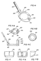
- Magnifying lens, and pre-surgical corneal hinge meter 120 is illustrated in FIG. 4.
- This lens/meter is an independent component of the instrument and allows for setting of the stop position using screw 260 by placing the meter under the guide ring assembly prior to attachment on the ocular globe.
- Reference marks 123, 124 are etched in the lens for precisely measuring the desired extent of corneal hinge according to the measured diameter of the cornea.
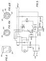
- FIG. 5 illustrates a preferred embodiment of the automatic setback circuit which is placed in the electric motor circuit that energizes the driving means described above.
- guide ring 200 may be equipped with upwardly extending pivot post 203 that is engageable with output shaft 242 partially disposed within cutting head 230.
- output shaft 242 is positioned in engagement with the gear assembly that cooperates with the driving means such that a torque is applied to the output shaft by a drive motor connected to driving means 20 of the microkeratome.
- the output shaft if unconstrained, will rotate.
- Pivot post 203 is further designed to support the weight of the microkeratome via guide tube 236 about the output shaft, at support ring 209. In this fashion, the cutting head is driven across guide ring 200, by the action of drive gears against a worm gear on the fixed output shaft, through an arcuate path in a smooth, controlled fashion.
- microkeratome 210 is driven across the guide ring by the engagement of a drive gear with a gear track positioned on the surface of the guide ring.
- the arcuate sweeping motion of the cutting head of microkeratome 210 is believed to provide a much smoother surgical stroke since variables resulting from the surgeon's input are eliminated.
- output shaft 242 and pivot post 203 are placed in engagement, the gear assemblies and associated bearings within cutting head 230 along with the electric motor and driving means 20 control the motion of the microkeratome.
- the smooth motion of the instrument is largely dependent on the precise manufacturing tolerances for the gear assemblies and the support structure provided by the pivot post at the output shaft, rather than the expertise of the surgeon.
- driving means 20 includes a speed reduction system and an eccentric pin assembled in a single unit.
- a drive motor (not shown) produces a torque in shaft 21, which rotates central shaft 22 that terminates in small eccentric pin 25 and worm gear 24.
- Worm gear 24 ultimately drives the microkeratome across the guide ring about pivot post 203, as explained further below.
- Driving unit 20 also includes externally threaded neck portion 23 which permits it to engage complementary internally threaded neck portion 231 on cutting head 230, as shown in FIG. 8.
- Threaded cylindrical portion 231 extends outwardly from hollow cavity 229, which houses blade holder 270. Cavity 239 exhibits a greater width than blade holder 270 so as to permit reciprocating movement of the blade holder in a horizontal plane.
- cutting head 230 also contains cylindrical cavities that house first and second worm shafts 241 and 242.
- the first and second worn shafts are mounted for rotation about their respective axes, positioned 90° relative to one another as shown in FIGS. 8 and 9.
- Worm gear 24 of central shaft 22 of driving means 20 engages reduced diameter gear portion 232 of first worm 241 to transmit torque from central shaft 22 to first worm 241.
- Worm 241 is further equipped with worm gear 233 adjacent one of its ends, and is mounted for rotation about its axis.
- Worm gear 233 of first worm 241 engages reduced diameter gear portion 244 of second worm 242, which is also referred to as the output shaft. In this fashion, torque delivered from central shaft 22 is transmitted through worn shaft 241 to output shaft 242, which is mounted for rotation about an axis that is oriented 90° to the axis of first worm 241.
- Cutting head output shaft 242 terminates in a gear toothed coupling system 235 that engages an opposing gear toothed coupling system 204 of pivot post 203.
- output shaft 242 and coupling teeth 235 would rotate freely upon activation of the drive motor prior to engagement with coupling teeth 204 of post 203.
- the engagement of the opposing coupling teeth fix output shaft 242 to guide ring 200, preventing the output shaft from rotating relative to the guide ring.
- the torque applied by first worm 241 to output shaft 242 results in a back-drive rotation of worm 241 about output shaft 242.
- cutting bead 230 is provided with cavity 239A accessible through a lateral slot inclined at an angle between 26° and 30° along plane 239B, as shown in FIG. 8A.
- the inclined lateral slot permits the insertion or ingress of head 272 of blade holder 270, which are also illustrated in FIGS. 11-11B.
- Cavity 239 thus houses blade holder 270, while cavity 239a contains blade 60, shown in FIG. 3, which is mounted to head 272 via blade opening 61. In this manner, blade holder 270 and blade 60 are free to move horizontally by the rotation of eccentric pin 25 within vertical slot 271 of blade holder 270.
- the front, lower portion of cutting head 230 carries float head 250, also referred to as a plaque, for compressing the cornea ahead of the cutting blade so as to provide a desired depth of cut and thickness of the resulting corneal flap.
- Float head 250 is mounted between lover vertical support arms positioned on either side of the float head, about shaft 254 which is carried for rotation within openings 239C in the support arms. The openings thus support the shaft for the rotation of float head 250.
- Float head 250 of microkeratome 210 is relatively short in length and exhibits a triangular shape with a central eccentric bore 251 through which rotation about shaft 254 is accomplished, as shown in FIG. 6 and 17.
- Eccentric bore 251 permits the selection of different cutting heights with respect to the edge of the blade, and as a result different thicknesses for the resulting corneal flap.
- Shaft 254 is provided with raised boss members or positioning members on one of its ends that permit it to be selectively positioned within the support arms.
- one of the float head support arms is equipped with slots 239D for engagement with the positioning members 252 of the float head.
- Spring 253 is positioned in the opening in the other float head support arm about shaft 254, to permit positioning members 252 to be yieldably displaced from slots 239D to make the desired selection among the three faces of the float head. In this manner, float head 250 is easily rotated to a desired cutting depth and then locked in place by allowing spring 253 to urge positioning members 252 back into engagement with slots 239D.
- microkeratome 210 equipped with an optional guide assembly for ensuring that the cutting head does not uncouple from guide ring 200.
- cutting head 230 may be provided with guide wheel 239E that is mounted for rotation to one of the float head support arms, as shown in FIG. 8.
- Shoulder member 202 affixed to guide ring 200 serves as a guide for the passage of wheel 239E and prevents the uncoupling of the cutting head with the guide ring during the corneal incision.
- This guide assembly is thus secondary to the guide provided by the engagement of pin 237 with circular groove 206, as explained further below.
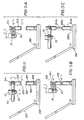
- the pivot post may be tubular and have an opening through the top thereof that is adapted for engagement with splines 242a positioned along the length of the output shaft as illustrated in FIG. 9C.
- the splined shaft includes a guide tube (not shown) similar to guide tube 236 of the preferred embodiment, having an inner diameter that is greater than the outer diameter of the tubular pivot post.
- the guide tube includes an internal pin 237 that aligns splines 242a of the output shaft properly within pivot post 203a when the pin is positioned within groove 205a formed on the outer surface of the pivot post. Pin 237 of the guide tube further ensures that the instrument remains coupled to guide ring 200 by engaging circular groove 206a as the cutting head is driven about an arcuate path over the guide ring.
- pivot post 203 and output shaft 242 are equipped with opposing coupling teeth that are adapted for engagement with one another.
- the output shaft is provided within guide tube 236 that is equipped with pin 237 for properly aligning teeth 235 of the output shaft with teeth 204 of the pivot post when the pin is placed within groove 205 in the pivot post.
- Pin 237 further engages circular groove 206 at the bottom of post 203 to ensure that cutting head 230 remains coupled to guide ring 200 during the cutting motion of the instrument across the guide ring.
- the present invention is thus well suited for making corneal incisions in any direction.
- the present invention is capable of making incisions from the inferior portion to the superior portion (i.e., lower to upper) of the cornea to create corneal flap 151 and hinge 152 in the superior (upper) quadrant of the eye, as shown in FIG. 15 studies have shown that such superior hinges are much less likely to experience ablation and traumatic displacement following surgery than a conventional nasal hinge.
- a nasal hinge cannot prevent movement of the corneal flap under the vertical reciprocating motion of the eyelid.
- a superior or upper hinge will keep the corneal flap in place under blinking action of the eyelid.
- adjustable stop means 260 similar to that described in the previous embodiment, that limits the sweeping motion of cutting head 230 across guide ring 200 to provide the appropriate extent of corneal hinge.
- the stop means are adjusted by merely turning the screw that extends through arm 207 to vary the point at which stop member 238 of cutting head 230 contacts screw 260.
- the control circuit shown schematically in FIG. 5 automatically returns the instrument to its starting position.
- the desired thickness of the corneal flap or disc to be created must be determined. In many cases, it will not be necessary to remove float head 250 from the instrument, since the float head is provided with three faces for creating three distinct depths of corneal incision.
- the float head is pulled toward the support arm carrying spring 253 and is rotated to seek the desired thickness as indicated by indica that is pre-marked on the float head or plague.
- the adjustable float head of the present invention has the important characteristic of inducing only a partial flattening of the cornea (less than 8 millimeters) at the time that the cut is carried out, which is different from other known microkeratomes that flatten more than half of the entire section of the cornea.
- this characteristic results primarily from the small surface area exhibited by any one face of the float head.
- float head 250 could provide superior results independently of its adjustable feature.
- a sterilized blade 60 is assembled in blade holder 270 through the slot that extends between cavities 239 and 239A of the cutting head, by introducing head 272 of the blade holder into blade opening 261.
- Blade 60 is thereby mounted in the blade holder with the sharp edge of the blade is oriented in a downward direction following the angle of the line 239B, seen in FIG. 8A.
- slot 271 of the blade holder is positioned toward the upper part of the cutting head 230, to later permit the entry of the eccentric pin 25 on driving means 20.
- the drive motor is coupled to the microkeratome by threadably engaging neck 231 of the cutting head to neck 23 of driving means 20 connected to the motor.
- This engagement introduces eccentric pin 25 into slot 271 of blade holder 270, and further positions worm gear 24 in engagement with reduced diameter gear portion 232 of first worm 241.
- operation of the drive motor will induce horizontal reciprocal motion of blade holder 270 and blade 260 within the cutting head while simultaneously inducing rotation of output shaft 242 before it is coupled to pivot post 203.
- the blade when the drive motor is activated, the blade shall be moved at a relatively high speed while the output shaft is rotated at a relatively low speed.
- hinge regulating tool 120 is set in place atop the cornea in cooperation with guide ring 200 to measure and mark the size of the corneal hinge beneath the ring.
- the tool 120 is transparent and permits the surgeon to see the desired advance of the cutting blade magnified when it is placed under the ring, and to regulate the desired stop in accordance with the desired diameter of the resulting corneal disc, using marked diameters 123, 124 on the lower face of the lens 121 as a reference.
- Lens 120 is thus set in place to map the limit of travel by the microkeratome over guide ring 200 and to choose the desired diameter for the corneal disc, which variables are obtained by regulating stop means 260 and float head 250.
- guide ring 200 is affixed to the cornea by applying suction from a low pressure source through a cavity in arm 207 connected to the guide ring such that cornea 141 protrudes therethrough at an adequate pressure to maintain the ocular globe in a fixed position during the intended surgery. In this manner, the eyeball is immobilized relative to the guide ring and the intraocular pressure is regulated.
- the microkeratome is then placed on guide ring 200, as shown in FIGS. 6 and 9-9C.
- Tubular guide 236 of the microkeratome 36 is placed over pivot post 203 while pin 237 is oriented to align first with linear groove 205 and then with groove circular 206 which communicates with groove 205.
- the drive motor is activated to initiate the corneal incision, as indicated in FIG. 12.
- the microkeratome advances in an arcuate path as worm gear 244 rotates cutting head 230 about output shaft 242 at reduced diameter gear portion 233.
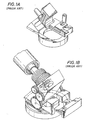
- Float head 250 produces a partial flattening of cornea 141 while the cutting blade performs the incision. This cutting action is continued across the arcuate path until stop member 238 encounters screw 260, defining corneal flap 151 and hinge 152 as shown in FIGS. 13 and 15. When this occurs, a voltage drop is produced in the system and the polarity of the current is reversed, returning the microkeratome to its point of origin.
- the relatively small surface area exhibited by the pivoting microkeratome of the present invention gives the instrument the capacity of operating without passing ever the edges of the guide ring. This permits the cutting head to be placed in its initial position and to be driven at the pivot post for cutting action in a sweeping arcuate path without stumbling over or interfering with the edges of the eye. More importantly, this permits the creation of a corneal hinge in the upper or superior quadrant. Thus, corneal disc or flap 151 which results from the action of the microkeratome is raised posteriorly such that hinge 152 remains in the superior quadrant. This of course permits the shaping of corneal stroma tissue 153, currently carried out with laser technology.
Landscapes
- Health & Medical Sciences (AREA)
- Ophthalmology & Optometry (AREA)
- Life Sciences & Earth Sciences (AREA)
- Animal Behavior & Ethology (AREA)
- Engineering & Computer Science (AREA)
- Biomedical Technology (AREA)
- Heart & Thoracic Surgery (AREA)
- Vascular Medicine (AREA)
- Nuclear Medicine, Radiotherapy & Molecular Imaging (AREA)
- Surgery (AREA)
- General Health & Medical Sciences (AREA)
- Public Health (AREA)
- Veterinary Medicine (AREA)
- Surgical Instruments (AREA)
- Steroid Compounds (AREA)
- Prostheses (AREA)
Claims (11)
- Microkératome (10, 210) pour réaliser une kératotomie lamellaire d'un globe oculaire, comprenant un anneau de guidage (104, 200) à placer sur le globe oculaire de sorte que la cornée du globe fasse saillie en son travers, des moyens (106, 107) pour fixer temporairement cet anneau (104, 200) au globe oculaire ; une lame (60, 312) à réaliser des résections cornéennes ; une tête de coupe (30, 40, 230) pour entraíner ladite lame (60, 312) au-dessus de l'anneau de guidage (104, 200) le long d'une trajectoire de coupe définie par ledit anneau de guidage ; un aileron de tête (50, 250, 311, 320, 330, 340, 350, 360, 370, 380) relié à ladite tête de coupe pour comprimer la cornée en avant de ladite lame (60, 312) de manière à fixer une forme et une épaisseur prédéterminées de la résection cornéenne ; et des moyens (20) pour entraíner ladite tête de coupe (30, 40, 230) et ledit aileron de tête (50, 250, 311, 320, 330, 340, 350, 360, 370, 380) au travers dudit anneau de guidage (104, 200), de sorte que la lame (60, 312) coupe au moins partiellement la cornée pour réaliser une kératotomie lamellaire, caractérisé en ce que ledit anneau de guidage (200) comprend un pivot (203, 203a) s'étendant vers le haut et en ce que les moyens d'entraínement (20) comportent un arbre de sortie (242) s'étendant partiellement à l'intérieur de ladite tête de coupe (230) pour coopérer avec le pivot (203, 203a) afin de contrarier l'arbre de sortie (240) dans sa rotation relative au pivot (203) et des moyens (22, 24, 232, 233, 242, 244) pour appliquer un couple à l'arbre de sortie (242) à l'intérieur de ladite tête de coupe (230) de sorte que cette tête de coupe (230) et l'aileron de tête (50, 250, 311, 320, 330, 340, 350, 360, 370, 380) sont animés d'une rotation autour de l'arbre de sortie (242) par lesdits moyens d'entraínement au-dessus de l'anneau de guidage (200) à une vitesse commandée.
- Microkératome selon la revendication 1, caractérisé en ce que ladite tête de coupe comporte un tube de guidage creux (236) s'étendant vers le bas autour de l'arbre de sortie (242) pour guider cet arbre de sortie dans sa coopération avec le pivot (203, 203a) et pour supporter le microkératome (210) au-dessus de l'anneau (200) à la base du pivot (203, 203a), le pivot (203 et l'arbre de sortie (242) possédant chacun des moyens dentés opposés et complémentaires (204, 235) pour une coopération axiale l'un avec l'autre.
- Microkératome selon la revendication 2, caractérisé en ce que le tube de guidage creux (236) possède un doigt (237) faisant saillie de sa surface intérieure radialement, en ce que le pivot (203, 203a) comporte une rainure (206, 206a) s'étendant axialement le long de sa surface extérieure de sorte que le doigt (237) pénètre dans la rainure (206, 206a) pour assurer que les dents (235) de l'arbre de sortie (242) soit correctement alignées pour leur prise avec les dents (204) du pivot (203, 203a).
- Microkératome selon l'une quelconque des revendications précédentes, caractérisé en ce que ladite tête de coupe comporte un tube de guidage creux (236) qui s'étend vers le bas autour de l'arbre de sortie (242) pour guider cet arbre de sortie dans son engagement avec le pivot (203a), l'arbre de sortie (242) possédant des cannelures (242a) sur sa surface extérieure et le pivot (203a) étant équipé d'une ouverture rainurée complémentaire de l'arbre de sortie cannelé (242).
- Microkératome selon l'une quelconque des revendications précédentes, caractérisé en ce que les moyens de butée (45, 105, 260) sont prévus pour limiter la plage sur laquelle ladite lame (60, 312) est déplacée le long du trajet de coupe de manière à définir une charnière cornéenne (152) dans la kératotomie lamellaire.
- Microkératome selon la revendication 5, caractérisé par des moyens pour inverser automatiquement lesdits moyens d'entraínement (20) quand les moyens de butée (45, 105, 260) limitent la plage de ladite lame (60, 312) de sorte que ledit microkératome (10, 210) retourne à la position à laquelle il était lorsque l'opération a commencé.
- Microkératome selon la revendication 1, caractérisé en ce que la tête (50, 250) comporte une paire de bras de support sensiblement parallèles (43, 44) et un aileron qui a une section transversale triangulaire avec trois faces et qui est supportée à rotation entre les bras de support autour d'un axe (54, 254) qui s'étend au travers de l'aileron, chacune des trois faces étant distante de l'axe (54, 254) de valeur différente, de sorte que l'épaisseur de la résection cornéenne est modifiée par la rotation de l'aileron jusqu'à placer la face désirée en position de comprimer la cornée.
- Microkératome selon la revendication 7, caractérisé en ce que l'aileron (50) est pourvu avec un indice (57) pour indiquer l'épaisseur de résection obtenue par la face sélectionnée.
- Microkératome selon l'une quelconque des revendications précédentes, caractérisé en ce que l'aileron comporte au moins une face courbe (360) de sorte qu'on réalise une résection cornéenne lenticulaire en comprimant la cornée avec cette face.
- Microkératome selon l'une quelconque des revendications précédentes, caractérisé en ce que l'aileron comporte au moins une face oblique (370, 380) de sorte qu'une résection cornéenne lenticulaire soit réalisée en comprimant la cornée avec cette face.
- Microkératome selon l'une quelconque des revendications précédentes, caractérisé en ce que les moyens d'entraínement comportent les moyens (21, 22, 25, 71) pour imprimer un mouvement oscillant à ladite lame (60, 312) qui est transversale au trajet de coupe.
Applications Claiming Priority (5)
| Application Number | Priority Date | Filing Date | Title |
|---|---|---|---|
| US77269896A | 1996-12-23 | 1996-12-23 | |
| US772698 | 1996-12-23 | ||
| US5677597P | 1997-08-25 | 1997-08-25 | |
| US56775 | 1997-08-25 | ||
| PCT/EP1997/007248 WO1998027901A1 (fr) | 1996-12-23 | 1997-12-22 | Microkeratome |
Publications (2)
| Publication Number | Publication Date |
|---|---|
| EP0971659A1 EP0971659A1 (fr) | 2000-01-19 |
| EP0971659B1 true EP0971659B1 (fr) | 2003-11-12 |
Family
ID=26735697
Family Applications (1)
| Application Number | Title | Priority Date | Filing Date |
|---|---|---|---|
| EP97954456A Expired - Lifetime EP0971659B1 (fr) | 1996-12-23 | 1997-12-22 | Microkeratome |
Country Status (10)
| Country | Link |
|---|---|
| US (2) | US5980543A (fr) |
| EP (1) | EP0971659B1 (fr) |
| JP (1) | JP3419789B2 (fr) |
| CN (1) | CN100515372C (fr) |
| AU (1) | AU716520B2 (fr) |
| BR (1) | BR9714079A (fr) |
| CA (1) | CA2275691C (fr) |
| DE (1) | DE69726189T2 (fr) |
| ES (1) | ES2210596T3 (fr) |
| WO (1) | WO1998027901A1 (fr) |
Families Citing this family (48)
| Publication number | Priority date | Publication date | Assignee | Title |
|---|---|---|---|---|
| US7166117B2 (en) | 1996-02-07 | 2007-01-23 | Hellenkamp Johann F | Automatic surgical device and control assembly for cutting a cornea |
| US6126668A (en) * | 1997-04-25 | 2000-10-03 | Innovative Optics, Inc. | Microkeratome |
| FR2767677B1 (fr) * | 1997-09-04 | 1999-11-05 | Moria Sa | Microkeratome pour chirurgie optalmologique |
| WO1999026568A1 (fr) * | 1997-11-21 | 1999-06-03 | Hawken Industries, Inc. | Systeme de chirurgie ophtalmologique et procede correspondant |
| ES2150863B1 (es) * | 1998-08-03 | 2001-06-16 | Novosalud Sl | Microqueratomo para la diseccion de lamelas de tejido corneal. |
| US6083236A (en) * | 1998-08-12 | 2000-07-04 | Feingold; Vladimir | Keratome method and apparatus |
| FR2789299B1 (fr) * | 1999-02-09 | 2001-05-11 | Khalil Hanna | Appareil chirurgical pour realiser une decoupe lamellaire de la cornee |
| US6165189A (en) | 1999-02-10 | 2000-12-26 | Sis, Ltd. | Microkeratome for performing lasik surgery |
| US6447526B1 (en) * | 1999-03-24 | 2002-09-10 | Cesar C. Carriazo | Disposable microkeratome blade housing |
| US6656196B1 (en) | 1999-04-12 | 2003-12-02 | Cesar C. Carriazo | Microkeratome cutting blade and method for performing corneal resections |
| US6296650B1 (en) * | 1999-04-12 | 2001-10-02 | Cesar C. Carriazo | Microkeratome |
| US6702832B2 (en) * | 1999-07-08 | 2004-03-09 | Med Logics, Inc. | Medical device for cutting a cornea that has a vacuum ring with a slitted vacuum opening |
| JP3497104B2 (ja) * | 1999-07-27 | 2004-02-16 | 株式会社長田中央研究所 | レーザ用止血鉗子 |
| JP2001095833A (ja) | 1999-09-30 | 2001-04-10 | Nidek Co Ltd | 角膜手術装置 |
| US6663644B1 (en) * | 2000-06-02 | 2003-12-16 | Med-Logics, Inc. | Cutting blade assembly for a microkeratome |
| US6451039B1 (en) | 2000-08-25 | 2002-09-17 | Alcon Universal, Ltd. | Microkeratome blade assembly |
| ATE508717T1 (de) | 2000-09-01 | 2011-05-15 | Alexander Dybbs | Ophthalmisches chirurgisches system |
| ES2279753T3 (es) * | 2000-09-08 | 2007-09-01 | Luigi Olivieri | Dispositivo para cirugia corneal. |
| US6679898B1 (en) * | 2000-09-27 | 2004-01-20 | The Regents Of The University Of California | Devices and methods for harvesting limbal stem cells |
| FR2815247B1 (fr) * | 2000-10-12 | 2002-12-20 | Moria Sa | Dispositif de chirurgie corneenne |
| ES2192123B1 (es) * | 2001-03-21 | 2005-02-01 | Novosalud, S.L. | Anillo de succion para microqueratomos. |
| FR2823664B1 (fr) * | 2001-04-18 | 2004-02-20 | Moria Sa | Ensemble de lame de coupe pour microkeratome |
| CA2445318C (fr) | 2001-04-25 | 2011-01-18 | Johann F. Hellenkamp | Ensemble de positionnement permettant de retenir et de positionner une cornee |
| US6569153B1 (en) * | 2001-06-28 | 2003-05-27 | Lahaye Leon C. | Multi-function surgical instrument for facilitating ophthalmic laser surgery |
| US6656197B1 (en) * | 2001-06-28 | 2003-12-02 | Lahaye Leon C. | Multi-function surgical instrument for facilitating ophthalmic laser surgery |
| US6497700B1 (en) * | 2001-06-28 | 2002-12-24 | Lahaye Leon C. | Multi-function surgical instrument for facilitating ophthalmic laser surgery |
| US7156859B2 (en) | 2001-07-23 | 2007-01-02 | Fos Holding S.A. | Device for separating the epithelium layer from the surface of the cornea of an eye |
| US6818004B2 (en) | 2001-10-24 | 2004-11-16 | Cesar C. Carriazo | Aspherical positioning ring |
| DE10152152B4 (de) * | 2001-10-25 | 2004-02-26 | Carl Zeiss Meditec Ag | Schneidvorrichtung |
| US7135028B2 (en) * | 2001-12-12 | 2006-11-14 | Nidek Co., Ltd. | Blade for corneal surgery and corneal surgical apparatus comprising the same |
| US20030114861A1 (en) * | 2001-12-14 | 2003-06-19 | Carriazo Cesar C. | Adjustable suction ring |
| WO2003075809A1 (fr) * | 2002-03-07 | 2003-09-18 | Stephen Glenn Slade | Microkeratome a ultrasons |
| US6805698B2 (en) * | 2002-04-03 | 2004-10-19 | Alcon, Inc. | Microkeratome blade |
| CA2521738C (fr) | 2003-04-07 | 2010-09-14 | Bausch & Lomb Incorporated | Systeme d'entrainement a barre stabilisatrice pour microkeratotome |
| US20050251185A1 (en) * | 2004-05-07 | 2005-11-10 | Gebauer Detlev P | Microkeratome and surgical blade for this |
| ATE361731T1 (de) * | 2004-08-12 | 2007-06-15 | Gebauer Gmbh & Co Kg | Mikrokeratom sowie chirurgische klinge hierfür |
| US20060206126A1 (en) * | 2005-02-01 | 2006-09-14 | Masahiro Sugimura | Blade for use in corneal surgery and corneal surgical apparatus having the same |
| US20060235380A1 (en) * | 2005-04-15 | 2006-10-19 | Restore Medical, Inc. | Tissue incision tool |
| JP4616107B2 (ja) * | 2005-07-20 | 2011-01-19 | 株式会社ニデック | 角膜手術装置及び角膜手術装置の本体部に装着されて使用されるヘッド部 |
| US7815657B2 (en) * | 2005-07-20 | 2010-10-19 | Nidek Co., Ltd. | Corneal surgical apparatus |
| JP4616106B2 (ja) * | 2005-07-20 | 2011-01-19 | 株式会社ニデック | 角膜手術装置及び角膜手術装置の本体部に装着されて使用されるヘッド部 |
| US7875045B2 (en) * | 2006-02-02 | 2011-01-25 | Nidek Co., Ltd. | Corneal incision apparatus and blade case for storing blade unit to be mounted in the corneal incision apparatus |
| US8070764B2 (en) * | 2006-03-01 | 2011-12-06 | Med-Logics, Inc. | Microkeratome with a detachable head |
| WO2010094766A1 (fr) * | 2009-02-20 | 2010-08-26 | Albert Daxer | Dispositif pour découper la cornée d'un œil |
| CN105105916B (zh) * | 2015-09-30 | 2017-05-31 | 长江大学 | 一种眼球术中制动器 |
| US10219939B1 (en) * | 2017-10-14 | 2019-03-05 | Samer Jaber Bashir | Surgical ophthalmic intra ocular access tool |
| CN108969187B (zh) * | 2018-08-02 | 2019-10-15 | 厦门大学 | 角膜超声显微环切系统 |
| CN111991140A (zh) * | 2020-09-10 | 2020-11-27 | 四川视佳生物科技有限公司 | 用于角膜移植手术的切割工具 |
Family Cites Families (21)
| Publication number | Priority date | Publication date | Assignee | Title |
|---|---|---|---|---|
| US35421A (en) * | 1862-05-27 | Improvement in grain-separators | ||
| US4173980A (en) * | 1977-02-25 | 1979-11-13 | Curtin Brian J | Corneal resurfacing apparatus and method |
| US4674503A (en) * | 1981-03-05 | 1987-06-23 | Peyman Gholam A | Controlled depth penetrant apparatus and method |
| US4688570A (en) * | 1981-03-09 | 1987-08-25 | The Regents Of The University Of California | Ophthalmologic surgical instrument |
| DE3433581C2 (de) | 1984-09-13 | 1986-08-07 | Fa. Carl Zeiss, 7920 Heidenheim | Vorrichtung zur lamellierenden, refraktiven Hornhautchirurgie |
| US4660556A (en) * | 1985-02-14 | 1987-04-28 | Techno Opthalmics International, Inc. | Method and apparatus for modifying corneal buttons |
| US4665914A (en) * | 1985-12-27 | 1987-05-19 | Emanuel Tanne | Automatic corneal surgery system |
| US4840175A (en) * | 1986-12-24 | 1989-06-20 | Peyman Gholam A | Method for modifying corneal curvature |
| US5591185A (en) * | 1989-12-14 | 1997-01-07 | Corneal Contouring Development L.L.C. | Method and apparatus for reprofiling or smoothing the anterior or stromal cornea by scraping |
| US5133726A (en) | 1990-02-14 | 1992-07-28 | Ruiz Luis A | Automatic corneal shaper |
| EP0607279A4 (fr) * | 1991-10-11 | 1995-08-09 | Clarence E Giraud | Instrument de sectionnement ameliore pour chirurgie lamellaire. |
| ATE206031T1 (de) * | 1992-04-10 | 2001-10-15 | Keravision Inc | Zentrierende, mit vakuum arbeitende führungsvorrichtung und dissektor für die hornhaut |
| US5318046A (en) * | 1992-09-23 | 1994-06-07 | Rozakis George W | Method for corneal reprofiling |
| CN1089824A (zh) * | 1993-01-19 | 1994-07-27 | 中国人民解放军军事医学科学院放射医学研究所 | 角膜切开器 |
| US5591174A (en) * | 1994-02-02 | 1997-01-07 | Chiron Vision Corporation | Microkeratome and method and apparatus for calibrating a microkeratome |
| US5496339A (en) * | 1994-05-17 | 1996-03-05 | Koepnick; Russell G. | Universal automated keratectomy apparatus and method |
| US5586980A (en) * | 1994-10-14 | 1996-12-24 | Kremer; Frederic B. | Microkeratome |
| US5595570A (en) * | 1994-12-06 | 1997-01-21 | S.C.M.D., Ltd. | Keratome with spring loaded adjustable plate, cutting length adjustment plate, method of cutting a corneal flap, and gauge-mounted bracket for adjusting plate on keratome head |
| DE19540439C2 (de) * | 1995-10-30 | 1999-04-22 | Schwind Gmbh & Co Kg Herbert | Vorrichtung zur Hornhautchirurgie |
| US5591195A (en) * | 1995-10-30 | 1997-01-07 | Taheri; Syde | Apparatus and method for engrafting a blood vessel |
| US5624456A (en) * | 1996-02-07 | 1997-04-29 | Hellenkamp; Johann F. | Automatic surgical device for cutting a cornea |
-
1997
- 1997-12-22 AU AU58596/98A patent/AU716520B2/en not_active Expired
- 1997-12-22 DE DE69726189T patent/DE69726189T2/de not_active Expired - Lifetime
- 1997-12-22 WO PCT/EP1997/007248 patent/WO1998027901A1/fr not_active Ceased
- 1997-12-22 ES ES97954456T patent/ES2210596T3/es not_active Expired - Lifetime
- 1997-12-22 BR BR9714079-1A patent/BR9714079A/pt not_active IP Right Cessation
- 1997-12-22 EP EP97954456A patent/EP0971659B1/fr not_active Expired - Lifetime
- 1997-12-22 CN CNB971809402A patent/CN100515372C/zh not_active Expired - Lifetime
- 1997-12-22 JP JP52840398A patent/JP3419789B2/ja not_active Expired - Lifetime
- 1997-12-22 CA CA002275691A patent/CA2275691C/fr not_active Expired - Lifetime
-
1998
- 1998-01-02 US US09/002,515 patent/US5980543A/en not_active Expired - Fee Related
-
1999
- 1999-11-08 US US09/436,379 patent/US6302896B1/en not_active Expired - Lifetime
Also Published As
| Publication number | Publication date |
|---|---|
| CA2275691C (fr) | 2002-09-10 |
| DE69726189D1 (de) | 2003-12-18 |
| CN1241920A (zh) | 2000-01-19 |
| JP3419789B2 (ja) | 2003-06-23 |
| BR9714079A (pt) | 2000-05-02 |
| US6302896B1 (en) | 2001-10-16 |
| DE69726189T2 (de) | 2004-09-09 |
| WO1998027901A1 (fr) | 1998-07-02 |
| AU716520B2 (en) | 2000-02-24 |
| ES2210596T3 (es) | 2004-07-01 |
| CN100515372C (zh) | 2009-07-22 |
| CA2275691A1 (fr) | 1998-07-02 |
| JP2000505694A (ja) | 2000-05-16 |
| US5980543A (en) | 1999-11-09 |
| AU5859698A (en) | 1998-07-17 |
| EP0971659A1 (fr) | 2000-01-19 |
Similar Documents
| Publication | Publication Date | Title |
|---|---|---|
| US5980543A (en) | Microkeratome and method of performing corneal resections | |
| US5658303A (en) | Universal automated keratectomy apparatus and method | |
| US7207998B2 (en) | Intracorneal lens placement method and apparatus | |
| EP0906072B1 (fr) | Instrument chirurgical automatique d'incision corneenne | |
| US20050049621A1 (en) | Intracorneal lens placement method and apparatus | |
| US6656196B1 (en) | Microkeratome cutting blade and method for performing corneal resections | |
| US6296650B1 (en) | Microkeratome | |
| EP1420733B1 (fr) | Keratotome | |
| US20010018590A1 (en) | Microkeratome | |
| CA2572504A1 (fr) | Procede et appareil de mise en place d'une lentille intracorneenne | |
| TW487570B (en) | Microkeratome and method for performing corneal resections | |
| WO2006007545A2 (fr) | Procede et appareil de mise en place d'une lentille intracorneenne | |
| HK1108620A (en) | Improved automatic surgical device for cutting a cornea | |
| HK1020491B (en) | Improved automatic surgical device for cutting a cornea |
Legal Events
| Date | Code | Title | Description |
|---|---|---|---|
| PUAI | Public reference made under article 153(3) epc to a published international application that has entered the european phase |
Free format text: ORIGINAL CODE: 0009012 |
|
| 17P | Request for examination filed |
Effective date: 19990625 |
|
| AK | Designated contracting states |
Kind code of ref document: A1 Designated state(s): CH DE ES FR GB IT LI |
|
| GRAH | Despatch of communication of intention to grant a patent |
Free format text: ORIGINAL CODE: EPIDOS IGRA |
|
| GRAS | Grant fee paid |
Free format text: ORIGINAL CODE: EPIDOSNIGR3 |
|
| GRAA | (expected) grant |
Free format text: ORIGINAL CODE: 0009210 |
|
| AK | Designated contracting states |
Kind code of ref document: B1 Designated state(s): CH DE ES FR GB IT LI |
|
| REG | Reference to a national code |
Ref country code: GB Ref legal event code: FG4D |
|
| REG | Reference to a national code |
Ref country code: CH Ref legal event code: EP |
|
| RAP2 | Party data changed (patent owner data changed or rights of a patent transferred) |
Owner name: CARRIAZO, CESAR C. Owner name: INSTITUTO BARRAQUER DE AMERICA |
|
| REF | Corresponds to: |
Ref document number: 69726189 Country of ref document: DE Date of ref document: 20031218 Kind code of ref document: P |
|
| REG | Reference to a national code |
Ref country code: CH Ref legal event code: NV Representative=s name: BOVARD AG PATENTANWAELTE |
|
| REG | Reference to a national code |
Ref country code: ES Ref legal event code: FG2A Ref document number: 2210596 Country of ref document: ES Kind code of ref document: T3 |
|
| ET | Fr: translation filed | ||
| PLBE | No opposition filed within time limit |
Free format text: ORIGINAL CODE: 0009261 |
|
| STAA | Information on the status of an ep patent application or granted ep patent |
Free format text: STATUS: NO OPPOSITION FILED WITHIN TIME LIMIT |
|
| 26N | No opposition filed |
Effective date: 20040813 |
|
| REG | Reference to a national code |
Ref country code: CH Ref legal event code: PFA Owner name: INSTITUTO BARRAQUER DE AMERICA Free format text: INSTITUTO BARRAQUER DE AMERICA#AVENIDA 100 NO. 18A-51#BOGOTA (CO) $ CARRIAZO, CESAR C.#KRA 59B NO. 79-261#BARRANQUILLA (CO) -TRANSFER TO- INSTITUTO BARRAQUER DE AMERICA#AVENIDA 100 NO. 18A-51#BOGOTA (CO) $ CARRIAZO, CESAR C.#KRA 59B NO. 79-261#BARRANQUILLA (CO) |
|
| REG | Reference to a national code |
Ref country code: DE Ref legal event code: R082 Ref document number: 69726189 Country of ref document: DE Representative=s name: SCHAUMBURG UND PARTNER PATENTANWAELTE MBB, DE Ref country code: DE Ref legal event code: R082 Ref document number: 69726189 Country of ref document: DE Representative=s name: SCHAUMBURG & PARTNER PATENTANWAELTE MBB, DE Ref country code: DE Ref legal event code: R082 Ref document number: 69726189 Country of ref document: DE Representative=s name: SCHAUMBURG & PARTNER PATENTANWAELTE GBR, DE |
|
| REG | Reference to a national code |
Ref country code: FR Ref legal event code: PLFP Year of fee payment: 19 |
|
| REG | Reference to a national code |
Ref country code: FR Ref legal event code: PLFP Year of fee payment: 20 |
|
| PGFP | Annual fee paid to national office [announced via postgrant information from national office to epo] |
Ref country code: CH Payment date: 20161221 Year of fee payment: 20 Ref country code: GB Payment date: 20161222 Year of fee payment: 20 Ref country code: DE Payment date: 20161213 Year of fee payment: 20 |
|
| PGFP | Annual fee paid to national office [announced via postgrant information from national office to epo] |
Ref country code: FR Payment date: 20161222 Year of fee payment: 20 Ref country code: ES Payment date: 20161213 Year of fee payment: 20 |
|
| PGFP | Annual fee paid to national office [announced via postgrant information from national office to epo] |
Ref country code: IT Payment date: 20161223 Year of fee payment: 20 |
|
| REG | Reference to a national code |
Ref country code: DE Ref legal event code: R071 Ref document number: 69726189 Country of ref document: DE |
|
| REG | Reference to a national code |
Ref country code: CH Ref legal event code: PL |
|
| REG | Reference to a national code |
Ref country code: GB Ref legal event code: PE20 Expiry date: 20171221 |
|
| PG25 | Lapsed in a contracting state [announced via postgrant information from national office to epo] |
Ref country code: GB Free format text: LAPSE BECAUSE OF EXPIRATION OF PROTECTION Effective date: 20171221 |
|
| REG | Reference to a national code |
Ref country code: ES Ref legal event code: FD2A Effective date: 20180508 |
|
| PG25 | Lapsed in a contracting state [announced via postgrant information from national office to epo] |
Ref country code: ES Free format text: LAPSE BECAUSE OF EXPIRATION OF PROTECTION Effective date: 20171223 |