EP0971804B1 - Verfahren und vorrichtung zum verhindern des kontaktes von sauerstoff mit einer metallschmelze beim giessen - Google Patents
Verfahren und vorrichtung zum verhindern des kontaktes von sauerstoff mit einer metallschmelze beim giessen Download PDFInfo
- Publication number
- EP0971804B1 EP0971804B1 EP98909453A EP98909453A EP0971804B1 EP 0971804 B1 EP0971804 B1 EP 0971804B1 EP 98909453 A EP98909453 A EP 98909453A EP 98909453 A EP98909453 A EP 98909453A EP 0971804 B1 EP0971804 B1 EP 0971804B1
- Authority
- EP
- European Patent Office
- Prior art keywords
- casting
- oxygen
- fuel gas
- chamber
- combustion
- Prior art date
- Legal status (The legal status is an assumption and is not a legal conclusion. Google has not performed a legal analysis and makes no representation as to the accuracy of the status listed.)
- Expired - Lifetime
Links
- 238000005266 casting Methods 0.000 title claims abstract description 102
- QVGXLLKOCUKJST-UHFFFAOYSA-N atomic oxygen Chemical compound [O] QVGXLLKOCUKJST-UHFFFAOYSA-N 0.000 title claims abstract description 32
- 239000001301 oxygen Substances 0.000 title claims abstract description 32
- 229910052760 oxygen Inorganic materials 0.000 title claims abstract description 32
- 239000002184 metal Substances 0.000 title claims abstract description 24
- 238000000034 method Methods 0.000 title claims abstract description 19
- 150000001875 compounds Chemical class 0.000 claims abstract 2
- 230000000266 injurious effect Effects 0.000 claims abstract 2
- 239000002737 fuel gas Substances 0.000 claims description 30
- 239000011261 inert gas Substances 0.000 claims description 28
- 238000002485 combustion reaction Methods 0.000 claims description 16
- 239000007789 gas Substances 0.000 claims description 16
- 238000009749 continuous casting Methods 0.000 claims description 8
- 238000007789 sealing Methods 0.000 claims description 7
- 239000000203 mixture Substances 0.000 claims description 5
- 229930195733 hydrocarbon Natural products 0.000 claims description 4
- 150000002430 hydrocarbons Chemical class 0.000 claims description 4
- VNWKTOKETHGBQD-UHFFFAOYSA-N methane Chemical compound C VNWKTOKETHGBQD-UHFFFAOYSA-N 0.000 claims description 4
- 229910000831 Steel Inorganic materials 0.000 claims description 3
- 239000007788 liquid Substances 0.000 claims description 3
- 239000010959 steel Substances 0.000 claims description 3
- 239000004215 Carbon black (E152) Substances 0.000 claims description 2
- HSFWRNGVRCDJHI-UHFFFAOYSA-N alpha-acetylene Natural products C#C HSFWRNGVRCDJHI-UHFFFAOYSA-N 0.000 claims description 2
- 125000002534 ethynyl group Chemical group [H]C#C* 0.000 claims description 2
- 239000000126 substance Substances 0.000 claims description 2
- 238000006243 chemical reaction Methods 0.000 claims 2
- -1 etc. Substances 0.000 claims 1
- 238000004868 gas analysis Methods 0.000 claims 1
- 230000001105 regulatory effect Effects 0.000 claims 1
- 238000010405 reoxidation reaction Methods 0.000 abstract description 6
- 239000000155 melt Substances 0.000 description 6
- 239000000567 combustion gas Substances 0.000 description 5
- 230000035515 penetration Effects 0.000 description 3
- XKRFYHLGVUSROY-UHFFFAOYSA-N Argon Chemical compound [Ar] XKRFYHLGVUSROY-UHFFFAOYSA-N 0.000 description 2
- IJGRMHOSHXDMSA-UHFFFAOYSA-N Atomic nitrogen Chemical compound N#N IJGRMHOSHXDMSA-UHFFFAOYSA-N 0.000 description 2
- 229910044991 metal oxide Inorganic materials 0.000 description 2
- 150000004706 metal oxides Chemical class 0.000 description 2
- 239000000843 powder Substances 0.000 description 2
- 230000005855 radiation Effects 0.000 description 2
- UGFAIRIUMAVXCW-UHFFFAOYSA-N Carbon monoxide Chemical compound [O+]#[C-] UGFAIRIUMAVXCW-UHFFFAOYSA-N 0.000 description 1
- 206010061218 Inflammation Diseases 0.000 description 1
- 238000010521 absorption reaction Methods 0.000 description 1
- 229910052786 argon Inorganic materials 0.000 description 1
- 230000004888 barrier function Effects 0.000 description 1
- 238000001816 cooling Methods 0.000 description 1
- 238000005336 cracking Methods 0.000 description 1
- 230000007547 defect Effects 0.000 description 1
- 239000003546 flue gas Substances 0.000 description 1
- 230000001976 improved effect Effects 0.000 description 1
- 230000004054 inflammatory process Effects 0.000 description 1
- 238000005259 measurement Methods 0.000 description 1
- 238000002844 melting Methods 0.000 description 1
- 230000008018 melting Effects 0.000 description 1
- 229910052757 nitrogen Inorganic materials 0.000 description 1
Images

Classifications
-
- B—PERFORMING OPERATIONS; TRANSPORTING
- B22—CASTING; POWDER METALLURGY
- B22D—CASTING OF METALS; CASTING OF OTHER SUBSTANCES BY THE SAME PROCESSES OR DEVICES
- B22D11/00—Continuous casting of metals, i.e. casting in indefinite lengths
- B22D11/06—Continuous casting of metals, i.e. casting in indefinite lengths into moulds with travelling walls, e.g. with rolls, plates, belts, caterpillars
- B22D11/0622—Continuous casting of metals, i.e. casting in indefinite lengths into moulds with travelling walls, e.g. with rolls, plates, belts, caterpillars formed by two casting wheels
-
- B—PERFORMING OPERATIONS; TRANSPORTING
- B22—CASTING; POWDER METALLURGY
- B22D—CASTING OF METALS; CASTING OF OTHER SUBSTANCES BY THE SAME PROCESSES OR DEVICES
- B22D11/00—Continuous casting of metals, i.e. casting in indefinite lengths
- B22D11/06—Continuous casting of metals, i.e. casting in indefinite lengths into moulds with travelling walls, e.g. with rolls, plates, belts, caterpillars
- B22D11/0637—Accessories therefor
- B22D11/0697—Accessories therefor for casting in a protected atmosphere
-
- B—PERFORMING OPERATIONS; TRANSPORTING
- B22—CASTING; POWDER METALLURGY
- B22D—CASTING OF METALS; CASTING OF OTHER SUBSTANCES BY THE SAME PROCESSES OR DEVICES
- B22D11/00—Continuous casting of metals, i.e. casting in indefinite lengths
- B22D11/06—Continuous casting of metals, i.e. casting in indefinite lengths into moulds with travelling walls, e.g. with rolls, plates, belts, caterpillars
- B22D11/0637—Accessories therefor
- B22D11/064—Accessories therefor for supplying molten metal
- B22D11/0642—Nozzles
-
- B—PERFORMING OPERATIONS; TRANSPORTING
- B22—CASTING; POWDER METALLURGY
- B22D—CASTING OF METALS; CASTING OF OTHER SUBSTANCES BY THE SAME PROCESSES OR DEVICES
- B22D11/00—Continuous casting of metals, i.e. casting in indefinite lengths
- B22D11/12—Accessories for subsequent treating or working cast stock in situ
-
- B—PERFORMING OPERATIONS; TRANSPORTING
- B22—CASTING; POWDER METALLURGY
- B22D—CASTING OF METALS; CASTING OF OTHER SUBSTANCES BY THE SAME PROCESSES OR DEVICES
- B22D27/00—Treating the metal in the mould while it is molten or ductile ; Pressure or vacuum casting
- B22D27/003—Treating the metal in the mould while it is molten or ductile ; Pressure or vacuum casting by using inert gases
Definitions
- the invention relates to a method for preventing the contact of Oxygen with a molten metal during continuous casting, the Molten metal flows into and out of a casting space bounded by walls this emerges as a strand, and a device for performing the Procedure.
- JP-A2 4-300049 describes a sealing device between two rotating in opposite directions Casting rolls and a cover in a two-roll casting process known by an inert gas supply and a fuel gas supply is interspersed.
- the towards Casting rolls rotating in the melt bath are included in a first treatment step Inert gas purged, causing the entry of larger amounts of atmospheric oxygen to the Melting bath is prevented.
- the fuel gas nevertheless entering the gap between the casting roll surface and the sealing device Proportion of atmospheric oxygen burned.
- this solution does not do that Penetration of combustion gases and therefore not the complete penetration of Prevents oxygen in the melt room. Such complete combustion that none Residual oxygen content can not be guaranteed.
- the invention aims at avoiding these disadvantages and difficulties and presents itself the task, a method of the type described above and a device for Continuous casting to create the contact of oxygen with a molten metal can be prevented and which completely prevent reoxidation, and indeed then when there is heavy wear on the between the casting space Walls existing columns comes.
- the so-called laminar underlayer namely those adhering to the walls forming the casting space or entrained air layer and the introduction of combustion gases with residual oxygen to be avoided.
- This object is achieved in a method of the type described in the introduction in that after burning the fuel gas on the thereby freed of oxygen An inert gas is applied to the casting roll surface.
- combustion 1 to 50% is performed substoichiometrically.
- Gaseous hydrocarbon such as methane, acetylene, etc. are advantageously used as fuel gas. or mixtures thereof or also forming gas, such as N2H2 mixed gases.
- Another preferred embodiment is characterized in that the oxygen is burned by means of gases and / or liquids which have a temperature between 0 and 300 ° C, preferably preheated, are used and further advantageously with a Pressure between 0.5 and 5 bar can be used. This is particularly advantageous Hydrocarbons.
- Another preferred embodiment is characterized in that immediately adjacent to the zone of oxygen combustion on a wall delimiting the casting space the inert gas in a layer with a thickness of at least 0.5 mm, preferably at least 5 mm; and preferably with an inflow pressure between 0.6 and 1.5 times, preferably between 0.95 and 1.05 times atmospheric pressure versus Wall is streaming.
- a device with which contact of oxygen with a molten metal during continuous casting of a metal strip, preferably steel strip, after the Two-roll casting can be prevented consists of two counter-rotating Casting rolls with parallel roll axes and two side dams together form a casting room for the absorption of molten metal and with a cover, which is arranged above the casting room and this upwards seals, as well as with a sealing device that prevents the entry of air along one of the Cover and the rotating casting rolls formed gap in the casting room is prevented by a fuel gas supply and an inert gas supply characterized in that the sealing device from an atmosphere side in the vicinity of the Gap between the rotating casting rolls and the cover hood burner, preferably gas burner, is formed and a between the cover and the burner Inert gas supply is arranged.
- An advantageous design of the burner is given in that the burner from a Distance from the casting roll surface arranged, in the direction of the casting roll axis extending fuel gas chamber and with a feed line for fuel gas and at least one against the casting roll surface, preferably obliquely and opposite directed towards the direction of movement of the casting rolls against the roll surface Outlet opening for fuel gas is equipped.
- the outlet opening for fuel gas can both be designed as a slot nozzle as well as a round nozzle.
- Important for the complete Combustion of the atmospheric oxygen is that in front of the hood and the Casting roll formed gap is maintained a continuous flame front.
- the outlet openings for the fuel gas open into a flame chamber open to the surface of the casting roll.
- This also makes it possible to reduce fuel gas consumption, because of the Flame chamber and the casting roll surface a largely closed space is created, in which the inflow of air only through the gap between the wall the flame chamber and the casting roll surface is possible.
- The is improved Effect of the flame chamber in that it is connected to an air supply and has a connection for a gas analyzer. With the air supply, a targeted Control of the combustion depending on that determined by the gas analyzer Flue gas composition possible.
- the inert gas supply has a nozzle trained outlet opening, which is inclined against the casting roll surface, preferably and opposite to the direction of movement of the casting rolls against the casting roll surface is directed.
- a nozzle trained outlet opening which is inclined against the casting roll surface, preferably and opposite to the direction of movement of the casting rolls against the casting roll surface is directed.
- Fig. 1 shows a cross section through the two-roll casting machine with the invention Sealing device in two embodiments.
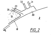
- FIG. 2 shows a detail from FIG. 1 of the burner according to the invention with a Flame chamber.
- the two-roll caster as shown schematically in section in FIG. 1, has two driven casting rolls 1, 2, the roll axes 3, 4 of which are arranged parallel to one another lie in a horizontal plane.
- the two rotating in opposite directions in the direction of arrow 5, 6 Casting rolls 1, 2 are with an internal cooling, not shown, for the Casting roll jacket provided, which forms the casting roll surface 7.
- On the face side, side dams 8 are sufficiently close to the casting rolls 1, 2 arranged. From the casting rolls 1, 2 and the side dams 8 is a Casting chamber 9 is formed, in which one, not shown Melt container or a distribution vessel by using a Outlet openings 11 provided feed nozzle 10 melt 20 is introduced.
- the casting chamber 9 is upwards, opposite the casting rolls 1, 2 and opposite limited the side dams with a cover 13, the melt side has a refractory lining 14 to pre-melt the melt 20 Protect heat loss and protect against reoxidation from atmospheric oxygen.
- a support device 15 for the cover 13 opposite one stationary frame 16 is adjustable with adjusting elements 17, a Desired minimum gap 18 between the cover 13 and the Casting rolls 1, 2 set.
- the cover 13 is from the feed nozzle 10 enforced, with as little as possible between these two components Annular gap is provided, which may be covered by a seal becomes.
- a gas burner 23 is arranged in front of these columns 18.
- the Gas burner consists of one in the direction of the casting roll axis extending fuel gas chamber 24, is to a supply line 25 for fuel gas connected and has one directed against the casting roll surface Exit opening 26 for fuel gas.
- the embodiment shown in FIG. 1 is the outlet opening 26 the fuel gas chamber 24 radially onto the casting roll surface 7 of the casting rolls 2 directed.
- the embodiment is the outlet opening 26 from the combustion gas chamber 24 obliquely and opposite to the direction of movement of the casting roll surface 7 directed.
- the outlet opening 26 is designed as a slot nozzle, wherein the slot-shaped outlet opening in the direction of the casting roll axis 4 extends.
- the outlet opening 26 can of course also be made of several short slots arranged one behind the other, which are Lined up over the entire length of the casting roll. Alternatively round nozzles are also possible, these nozzles being of a large number adjacent holes in the surface of the casting roll opposite wall of the fuel gas chamber are formed.
- FIG. 2 shows a detail of the burner already known from FIG. 1 23, wherein the outlet opening 26 from the combustion gas chamber 24 in a flame chamber 30 opens. Only in the flame chamber 30 by one U-shaped housing is formed, the fuel gases introduced to Inflammation brought and the imported oxygen burned.
- the Flame chamber 30 is to the casting roll surface 7 with a touching Lamellar seal protected against excessive air access.
- the flame chamber 30 is connected to an air supply 31 and has a connection 32 for a gas analyzer.
- the Inert gas supply 35 is constructive as a distance from the Casting roller surface 7 located inert gas chamber 36 and has an outlet opening 37 designed as a nozzle right half of the Fig. 1 embodiment shown radially on the Casting roll surface 7 and after in the left half of Fig. 1st embodiment shown obliquely and opposite to Direction of movement of the casting roll surface 7 directed.
- the inert gas supply With the inert gas supply, the time after the combustion of the fuel gas a thin layer of inert gas on the surface of the casting roll Casting roller surface applied, with the penetration of Combustion gases in the casting chamber 9 is prevented.
- a Layer thickness of at least 0.5 mm, preferably more than 5 mm is required.
Landscapes
- Engineering & Computer Science (AREA)
- Mechanical Engineering (AREA)
- Continuous Casting (AREA)
- Manufacture And Refinement Of Metals (AREA)
- Waste-Gas Treatment And Other Accessory Devices For Furnaces (AREA)
- Molds, Cores, And Manufacturing Methods Thereof (AREA)
- Manufacture Of Switches (AREA)
- Coupling Device And Connection With Printed Circuit (AREA)
Description
Claims (17)
- Verfahren zum Verhindern des Kontaktes von Sauerstoff mit einer Metallschmelze (20) beim Stranggießen nach dem Zweiwalzengießverfahren, wobei die Metallschmelze in einen von Wänden (1, 2, 13) begrenzten Gießraum einströmt und aus diesem als Strang austritt, wobei über allfällige Spalte (18) zwischen den Wänden (1, 2, 13) einzudringen versuchender und/oder an den Wänden (1, 2) anhaftender Sauerstoff unter Bildung einer für die Metallschmelze (20) unschädlichen Verbindung verbrannt wird, wobei eine von vorzugsweise vorgewärmten Brenngas gebildete Flamme direkt mit einer Wand (1, 2) des Gießraums in Kontakt gelangt und unmittelbar benachbart der Verbrennungszone des Sauerstoffs an einer den Gießraum begrenzenden Wand ein Inertgas gegen die Wand strömen gelassen wird, dadurch gekennzeichnet, daß nach dem Verbrennen des Brenngases auf der hierdurch von Sauerstoff befreiten Gießwalzenoberfläche ein Inertgas aufgebracht wird.
- Verfahren nach Anspruch 1, dadurch gekennzeichnet, daß die Verbrennung stöchiometrisch oder unterstöchiometrisch durchgeführt wird.
- Verfahren nach Anspruch 2, dadurch gekennzeichnet, daß die Verbrennung 1 bis 50 % unterstöchiometrisch durchgeführt wird.
- Verfahren nach einem oder mehreren der Ansprüche 1 bis 3, dadurch gekennzeichnet, daß als Brenngas gasförmiger Kohlenwasserstoff, wie Methan, Acetylen etc. oder Gemische davon oder auch Formiergas, wie N2H2-Mischgases, verwendet werden.
- Verfahren nach einem oder mehreren der Ansprüche 1 bis 4, dadurch gekennzeichnet, daß eine Messung der chemischen Zusammensetzung der bei der Verbrennung gebildeten Gase und in Abhängigkeit des Ergebnisses eine Regelung oder Steuerung des Umsetzvorganges, beispielsweise durch Einstellung des Verhältnisses Brenngasmenge zu Menge eines für den Brennvorgang erforderlichen Sauerstoffes, durchgeführt wird.
- Verfahren nach Anspruch 1, dadurch gekennzeichnet, daß der Sauerstoff mittels Gase und/oder Flüssigkeiten verbrannt wird, welche mit einer Temperatur zwischen 0 und 300°C, vorzugsweise vorgewärmt, eingesetzt werden.
- Verfahren nach Anspruch 6, dadurch gekennzeichnet, daß die Gase bzw. Flüssigkeiten mit einem Druck zwischen 0,5 und 5 bar eingesetzt werden.
- Verfahren nach einem oder mehreren der Ansprüche 5 bis 7, dadurch gekennzeichnet, daß zur Verbrennung Kohlenwasserstoffe eingesetzt werden.
- Verfahren nach einem oder mehreren der Ansprüche 1 bis 8, dadurch gekennzeichnet, daß unmittelbar benachbart der Zone der Sauerstoffverbrennung an einer den Gießraum begrenzenden Wand das Inertgas in einer Schicht mit einer Dicke von mindestens 0,5 mm, vorzugsweise mindestens 5 mm, und vorzugsweise mit einem Anströmdruck zwischen dem 0,6- bis 1,5-fachen, vorzugsweise zwischen dem 0,95-und dem 1,05-fachen Atmospäendruck gegen die Wand strömt.
- Vorrichtung zum Verhindern des Kontaktes von Sauerstoff mit einer Metallschmelze beim kontinuierlichen Gießen eines Metallbandes, vorzugsweise Stahlbandes, nach dem Zweiwalzengießverfahren, mit zwei gegenläufig rotierenden Gießwalzen (1, 2) mit parallel nebeneinanderliegenden Walzenachsen (3, 4) und zwei Seitendämmen (8), die zusammen einen Gießraum (9) für die Aufnahme von schmelzflüssigem Metall bilden und mit einer Abdeckhaube (13), die oberhalb des Gießraumes (9) angeordnet ist und diesen nach oben abschließt, sowie mit einer Abdichteinrichtung, die den Zutritt von Luft entlang eines von der Abdeckhaube (13) und den rotierenden Gießwalzen (1, 2) gebildeten Spaltes (18) in den Gießraum (9) verhindert, sowie einer Zuführleitung (25) für Brenngas und einer Inertgaszuführung (35), dadurch gekennzeichnet, daß die Abdichteinrichtung von einem atmosphärenseitig im Nahbereich des Spaltes (18) zwischen den rotierenden Gießwalzen (1, 2) und der Abdeckhaube (13) angeordneten Brenner (23), vorzugsweise Gasbrenner, gebildet ist und zwischen der Abdeckhaube (13) und dem Brenner (23) eine Inertgaszuführung (35) angeordnet ist.
- Vorrichtung nach Anspruch 10, dadurch gekennzeichnet, daß der Brenner (23) aus einer im Abstand von der Gießwalzenoberfläche (7) angeordneten, sich in Richtung der Gießwalzenachse (3, 4) erstreckenden Brenngaskammer (24) besteht und mit einer Zuführleitung (25) für Brenngas und mindestens einer gegen die Gießwalzenoberfläche (7), vorzugsweise schräg und entgegengesetzt zur Bewegungsrichtung der Gießwalzen (1, 2) gegen die Gießwalzenoberfläche (7) gerichteten Austrittsöffnung (26) für Brenngas ausgestattet ist.
- Vorrichtung nach Anspruch 11, dadurch gekennzeichnet, daß die Austrittsöffnung (26) für Brenngas als Schlitzdüse ausgebildet ist.
- Vorrichtung nach Anspruch 11, dadurch gekennzeichnet, daß die Austrittsöffnung (26) fiir Brenngas als Runddüse ausgebildet ist.
- Vorrichtung nach einem der Ansprüche 11 bis 13, dadurch gekennzeichnet, daß die Austrittsöffnungen (26) für das Brenngas in eine zur Gießwalzenoberfläche (7) offenen Flammenkammer (30) münden.
- Vorrichtung nach Anspruch 14, dadurch gekennzeichnet, daß die Flammemkammer (30) mit einer Luftzuführung (31) verbunden ist und einen Anschluß (32) für ein Gasanalysegerät aufweist.
- Vorrichtung nach einem der Ansprüche 10 bis 15, dadurch gekennzeichnet, daß die Inertgaszuführung (35) eine als Düse ausgebildete Austrittsöffnung (37) aufweist, die gegen die Gießwalzenoberfläche (7), vorzugsweise schräg und entgegengesetzt zur Bewegungsrichtung der Gießwalzen gegen die Gießwalzenoberfläche gerichtet ist.
- Vocrichturig nach einem der vorhergehenden Ansprüche 10 bis 16, dadurch gekennzeichnet, daß zwischen Brenner (23) und Inertgaszuführung (35) eine Dichtung, vorzugsweise eine Lamellendichtung, vorgesehen ist.
Applications Claiming Priority (3)
| Application Number | Priority Date | Filing Date | Title |
|---|---|---|---|
| IT97RM000078A IT1290929B1 (it) | 1997-02-14 | 1997-02-14 | Procedimento e dispositivo per impedire il contatto di ossigeno con una massa metallica fusa. |
| ITRM970078 | 1997-02-14 | ||
| PCT/EP1998/000787 WO1998035772A1 (de) | 1997-02-14 | 1998-02-12 | Verfahren zum verhindern des kontaktes von sauerstoff mit einer metallschmelze |
Publications (2)
| Publication Number | Publication Date |
|---|---|
| EP0971804A1 EP0971804A1 (de) | 2000-01-19 |
| EP0971804B1 true EP0971804B1 (de) | 2001-10-24 |
Family
ID=11404753
Family Applications (1)
| Application Number | Title | Priority Date | Filing Date |
|---|---|---|---|
| EP98909453A Expired - Lifetime EP0971804B1 (de) | 1997-02-14 | 1998-02-12 | Verfahren und vorrichtung zum verhindern des kontaktes von sauerstoff mit einer metallschmelze beim giessen |
Country Status (18)
| Country | Link |
|---|---|
| US (1) | US6443220B1 (de) |
| EP (1) | EP0971804B1 (de) |
| JP (1) | JP3983815B2 (de) |
| KR (1) | KR100525036B1 (de) |
| CN (1) | CN1077469C (de) |
| AT (1) | ATE207394T1 (de) |
| AU (1) | AU730891B2 (de) |
| BR (1) | BR9807224A (de) |
| CA (1) | CA2281700C (de) |
| CZ (1) | CZ288728B6 (de) |
| DE (1) | DE59801869D1 (de) |
| ES (1) | ES2168743T3 (de) |
| ID (1) | ID26592A (de) |
| IT (1) | IT1290929B1 (de) |
| PL (1) | PL192938B1 (de) |
| RU (1) | RU2195385C2 (de) |
| UA (1) | UA46886C2 (de) |
| WO (1) | WO1998035772A1 (de) |
Families Citing this family (2)
| Publication number | Priority date | Publication date | Assignee | Title |
|---|---|---|---|---|
| BR112019003702B1 (pt) * | 2016-08-29 | 2022-08-30 | Pyrotek, Inc | Sistema de submersão de sucata de metal fundido |
| CN109175338A (zh) * | 2018-09-20 | 2019-01-11 | 天津华北集团铜业有限公司 | 一种新型的浇包 |
Family Cites Families (17)
| Publication number | Priority date | Publication date | Assignee | Title |
|---|---|---|---|---|
| YU43229B (en) | 1980-05-09 | 1989-06-30 | Battelle Development Corp | Device for continuous band casting |
| SU946791A1 (ru) * | 1981-02-25 | 1982-07-30 | Всесоюзный научно-исследовательский и проектный институт титана | Устройство дл непрерывного лить легкоокисл ющихс металлов и сплавов |
| JPS59166356A (ja) | 1983-03-11 | 1984-09-19 | Hitachi Seisen Kk | 連続鋳造におけるフレ−ジング防止方法 |
| US4588015A (en) | 1984-10-17 | 1986-05-13 | Allied Corporation | Casting in an exothermic reducing flame atmosphere |
| DE3602594A1 (de) | 1986-01-29 | 1987-07-30 | Sundwiger Eisen Maschinen | Vorrichtung zum giessen von metallbaendern auf einem bewegten kuehlkoerper |
| US4987949A (en) * | 1988-07-29 | 1991-01-29 | Hitachi Zosen Corporation | Protective cover for surface of molten steel used in continuous casting apparatus |
| US5103895A (en) * | 1989-07-20 | 1992-04-14 | Nippon Steel Corporation | Method and apparatus of continuously casting a metal sheet |
| JPH0366453A (ja) * | 1989-08-03 | 1991-03-22 | Nippon Steel Corp | 双ロール式連続鋳造機 |
| FR2654657B1 (fr) | 1989-11-22 | 1992-03-20 | Siderurgie Fse Inst Rech | Dispositif de coulee continue de bandes minces de metal entre deux cylindres. |
| JPH0430049A (ja) * | 1990-05-25 | 1992-02-03 | Sekisui House Ltd | プレキャストコンクリート部材の接合用具 |
| JP2672195B2 (ja) * | 1991-03-27 | 1997-11-05 | 日立造船株式会社 | 移動鋳型壁を有する連続鋳造設備における湯面保護カバー |
| RU2025188C1 (ru) * | 1991-07-09 | 1994-12-30 | Конструкторско-технологический институт холодновысадочного и пружинного производства | Способ изготовления рельефных полостей формообразующего инструмента |
| JPH0523800A (ja) * | 1991-07-16 | 1993-02-02 | Kawasaki Steel Corp | 急冷凝固合金薄帯の製造方法及びその装置 |
| AU1955592A (en) | 1991-08-06 | 1993-02-11 | Olin Corporation | Casting of metal strip |
| US5293926A (en) | 1992-04-30 | 1994-03-15 | Allegheny Ludlum Corporation | Method and apparatus for direct casting of continuous metal strip |
| FR2727338A1 (fr) * | 1994-11-30 | 1996-05-31 | Usinor Sacilor | Dispositif de coulee continue entre cylindres a capotage d'inertage |
| US5563903A (en) * | 1995-06-13 | 1996-10-08 | Praxair Technology, Inc. | Aluminum melting with reduced dross formation |
-
1997
- 1997-02-14 IT IT97RM000078A patent/IT1290929B1/it active IP Right Grant
-
1998
- 1998-02-12 CZ CZ19992791A patent/CZ288728B6/cs not_active IP Right Cessation
- 1998-02-12 ES ES98909453T patent/ES2168743T3/es not_active Expired - Lifetime
- 1998-02-12 KR KR10-1999-7006579A patent/KR100525036B1/ko not_active Expired - Fee Related
- 1998-02-12 ID IDW990628A patent/ID26592A/id unknown
- 1998-02-12 WO PCT/EP1998/000787 patent/WO1998035772A1/de not_active Ceased
- 1998-02-12 UA UA99084540A patent/UA46886C2/uk unknown
- 1998-02-12 RU RU99119592/02A patent/RU2195385C2/ru not_active IP Right Cessation
- 1998-02-12 DE DE59801869T patent/DE59801869D1/de not_active Expired - Lifetime
- 1998-02-12 EP EP98909453A patent/EP0971804B1/de not_active Expired - Lifetime
- 1998-02-12 BR BR9807224-2A patent/BR9807224A/pt not_active IP Right Cessation
- 1998-02-12 AT AT98909453T patent/ATE207394T1/de active
- 1998-02-12 CN CN98802528A patent/CN1077469C/zh not_active Expired - Fee Related
- 1998-02-12 JP JP53534398A patent/JP3983815B2/ja not_active Expired - Fee Related
- 1998-02-12 PL PL335253A patent/PL192938B1/pl unknown
- 1998-02-12 CA CA002281700A patent/CA2281700C/en not_active Expired - Fee Related
- 1998-02-12 US US09/367,473 patent/US6443220B1/en not_active Expired - Lifetime
- 1998-02-12 AU AU63982/98A patent/AU730891B2/en not_active Ceased
Also Published As
| Publication number | Publication date |
|---|---|
| WO1998035772A1 (de) | 1998-08-20 |
| AU6398298A (en) | 1998-09-08 |
| CZ288728B6 (cs) | 2001-08-15 |
| CN1247489A (zh) | 2000-03-15 |
| ITRM970078A1 (it) | 1998-08-14 |
| US6443220B1 (en) | 2002-09-03 |
| UA46886C2 (uk) | 2002-06-17 |
| KR20000070346A (ko) | 2000-11-25 |
| KR100525036B1 (ko) | 2005-11-01 |
| CN1077469C (zh) | 2002-01-09 |
| PL335253A1 (en) | 2000-04-10 |
| BR9807224A (pt) | 2000-04-25 |
| DE59801869D1 (de) | 2001-11-29 |
| JP2001524880A (ja) | 2001-12-04 |
| CA2281700C (en) | 2006-09-12 |
| JP3983815B2 (ja) | 2007-09-26 |
| EP0971804A1 (de) | 2000-01-19 |
| ID26592A (id) | 2001-01-18 |
| CA2281700A1 (en) | 1998-08-20 |
| PL192938B1 (pl) | 2006-12-29 |
| ES2168743T3 (es) | 2002-06-16 |
| AU730891B2 (en) | 2001-03-15 |
| RU2195385C2 (ru) | 2002-12-27 |
| CZ279199A3 (cs) | 2000-07-12 |
| IT1290929B1 (it) | 1998-12-14 |
| ATE207394T1 (de) | 2001-11-15 |
Similar Documents
| Publication | Publication Date | Title |
|---|---|---|
| DE69503742T2 (de) | Vorrichtung zum Stranggiessen zwischen Giesswalzen mit Inertgasschutz | |
| DE69602633T2 (de) | Giessen eines Stahlbandes | |
| DE60011474T2 (de) | Giessen eines stahlbandes | |
| DE69400505T2 (de) | Schmelzofen mit Gaseinjektor | |
| DE3931392A1 (de) | Verfahren und vorrichtung zum zumindest zeitweise gleichzeitigen beaufschlagen einer metallschmelze mit einem gas und feinkoernigen feststoffen | |
| DE19817590C1 (de) | Variabel einsetzbare Kombilanze | |
| EP1181997A1 (de) | Verfahren und Vorrichtung zum kontinuierlichen Giessen von Stahlband aus Stahlschmelze | |
| EP1068035A1 (de) | Verfahren zum stranggiessen eines dünnen bandes sowie vorrichtung zur durchführung des verfahrens | |
| DE4231686C2 (de) | Verschlußplatte für einen Schiebeverschluß an einem eine Metallschmelze enthaltenden Behälter | |
| EP0859678B1 (de) | Verfahren und vorrichtung zum verschliessen einer abstichöffnung | |
| DE3627196C2 (de) | ||
| EP0971804A1 (de) | Verfahren zum verhindern des kontaktes von sauerstoff mit einer metallschmelze | |
| DE60316568T3 (de) | Bandtemperaturregelvorrichtung in einer kontinuierlichen bandgiessanlage | |
| DE69007272T2 (de) | Verfahren und Vorrichtung zum Abdichten der Spalte zwischen Elektrode und Deckel bei einem Elektroofen. | |
| EP0045365B1 (de) | Metalleinlauf in Stranggiessvorrichtungen mit bewegten Kokillenwänden | |
| EP2445663B1 (de) | Verfahren und vorrichtung zum erzeugen von stahlbändern mittels bandgiessen | |
| DE2310240C2 (de) | Verfahren zur Überwachung und Regelung der Entkohlung beim Roheisen- Frischen und Vorrichtung zur Durchführung des Verfahrens | |
| DE3925243A1 (de) | Schild zum schutz der oberflaeche von fluessigem stahl in stranggiessanlagen | |
| EP0961665A1 (de) | Verfahren zum verhindern des kontaktes von sauerstoff mit einer metallschmelze | |
| DE2534244A1 (de) | Schutzgasabdeckung fuer eine streifengiessvorrichtung | |
| DE4321478C2 (de) | Anlage zum kontinuierlichen Gießen zwischen beweglichen Wänden und Gießverfahren unter Verwendung dieser Anlage | |
| EP0182965A1 (de) | Verfahren zum Schutz der Düsen und der feuerfesten Auskleidung eines Gefässes zum Frischen einer Metallschmelze | |
| DE69211879T2 (de) | Brenner zur Russerzeugung und Ofen mit einem derartigen Brenner zur Russablagerung | |
| CH662073A5 (de) | Verfahren zum zufuehren einer metallschmelze und giessmaschine zur durchfuehrung des verfahrens. | |
| DE1295757B (de) | Vorrichtung zur Entnahme von fluessigem Metall und Schlacke aus der axial angeordneten Entleerungsoeffnung eines Drehrohrofens |
Legal Events
| Date | Code | Title | Description |
|---|---|---|---|
| PUAI | Public reference made under article 153(3) epc to a published international application that has entered the european phase |
Free format text: ORIGINAL CODE: 0009012 |
|
| 17P | Request for examination filed |
Effective date: 19990611 |
|
| AK | Designated contracting states |
Kind code of ref document: A1 Designated state(s): AT BE DE ES FR GB IT LU SE |
|
| RTI1 | Title (correction) |
Free format text: METHOD AND APPARATUS AVOIDING CONTACT BETWEEN OXYGEN AND MOLTEN METAL DURING CASTING |
|
| GRAG | Despatch of communication of intention to grant |
Free format text: ORIGINAL CODE: EPIDOS AGRA |
|
| GRAG | Despatch of communication of intention to grant |
Free format text: ORIGINAL CODE: EPIDOS AGRA |
|
| GRAH | Despatch of communication of intention to grant a patent |
Free format text: ORIGINAL CODE: EPIDOS IGRA |
|
| 17Q | First examination report despatched |
Effective date: 20010326 |
|
| GRAH | Despatch of communication of intention to grant a patent |
Free format text: ORIGINAL CODE: EPIDOS IGRA |
|
| GRAA | (expected) grant |
Free format text: ORIGINAL CODE: 0009210 |
|
| AK | Designated contracting states |
Kind code of ref document: B1 Designated state(s): AT BE DE ES FR GB IT LU SE |
|
| REF | Corresponds to: |
Ref document number: 207394 Country of ref document: AT Date of ref document: 20011115 Kind code of ref document: T |
|
| REF | Corresponds to: |
Ref document number: 59801869 Country of ref document: DE Date of ref document: 20011129 |
|
| REG | Reference to a national code |
Ref country code: GB Ref legal event code: IF02 |
|
| GBT | Gb: translation of ep patent filed (gb section 77(6)(a)/1977) |
Effective date: 20020212 |
|
| ET | Fr: translation filed | ||
| REG | Reference to a national code |
Ref country code: ES Ref legal event code: FG2A Ref document number: 2168743 Country of ref document: ES Kind code of ref document: T3 |
|
| PLBE | No opposition filed within time limit |
Free format text: ORIGINAL CODE: 0009261 |
|
| STAA | Information on the status of an ep patent application or granted ep patent |
Free format text: STATUS: NO OPPOSITION FILED WITHIN TIME LIMIT |
|
| 26N | No opposition filed | ||
| PG25 | Lapsed in a contracting state [announced via postgrant information from national office to epo] |
Ref country code: IT Free format text: LAPSE BECAUSE OF NON-PAYMENT OF DUE FEES Effective date: 20100212 |
|
| PGFP | Annual fee paid to national office [announced via postgrant information from national office to epo] |
Ref country code: LU Payment date: 20120222 Year of fee payment: 15 |
|
| PGFP | Annual fee paid to national office [announced via postgrant information from national office to epo] |
Ref country code: SE Payment date: 20120206 Year of fee payment: 15 Ref country code: GB Payment date: 20120208 Year of fee payment: 15 Ref country code: BE Payment date: 20120312 Year of fee payment: 15 |
|
| PGFP | Annual fee paid to national office [announced via postgrant information from national office to epo] |
Ref country code: AT Payment date: 20120111 Year of fee payment: 15 |
|
| PGFP | Annual fee paid to national office [announced via postgrant information from national office to epo] |
Ref country code: ES Payment date: 20120307 Year of fee payment: 15 |
|
| BERE | Be: lapsed |
Owner name: *ACCIAI SPECIALI TERNI S.P.A. Effective date: 20130228 Owner name: *VOEST-ALPINE INDUSTRIEANLAGENBAU G.M.B.H. Effective date: 20130228 |
|
| REG | Reference to a national code |
Ref country code: SE Ref legal event code: EUG |
|
| REG | Reference to a national code |
Ref country code: AT Ref legal event code: MM01 Ref document number: 207394 Country of ref document: AT Kind code of ref document: T Effective date: 20130228 |
|
| GBPC | Gb: european patent ceased through non-payment of renewal fee |
Effective date: 20130212 |
|
| PG25 | Lapsed in a contracting state [announced via postgrant information from national office to epo] |
Ref country code: AT Free format text: LAPSE BECAUSE OF NON-PAYMENT OF DUE FEES Effective date: 20130228 Ref country code: SE Free format text: LAPSE BECAUSE OF NON-PAYMENT OF DUE FEES Effective date: 20130213 |
|
| PG25 | Lapsed in a contracting state [announced via postgrant information from national office to epo] |
Ref country code: BE Free format text: LAPSE BECAUSE OF NON-PAYMENT OF DUE FEES Effective date: 20130228 Ref country code: GB Free format text: LAPSE BECAUSE OF NON-PAYMENT OF DUE FEES Effective date: 20130212 |
|
| REG | Reference to a national code |
Ref country code: ES Ref legal event code: FD2A Effective date: 20140509 |
|
| PGFP | Annual fee paid to national office [announced via postgrant information from national office to epo] |
Ref country code: FR Payment date: 20140212 Year of fee payment: 17 Ref country code: IT Payment date: 20140227 Year of fee payment: 17 |
|
| PG25 | Lapsed in a contracting state [announced via postgrant information from national office to epo] |
Ref country code: ES Free format text: LAPSE BECAUSE OF NON-PAYMENT OF DUE FEES Effective date: 20130213 |
|
| PGFP | Annual fee paid to national office [announced via postgrant information from national office to epo] |
Ref country code: DE Payment date: 20140417 Year of fee payment: 17 |
|
| PG25 | Lapsed in a contracting state [announced via postgrant information from national office to epo] |
Ref country code: LU Free format text: LAPSE BECAUSE OF NON-PAYMENT OF DUE FEES Effective date: 20130212 |
|
| REG | Reference to a national code |
Ref country code: DE Ref legal event code: R119 Ref document number: 59801869 Country of ref document: DE |
|
| REG | Reference to a national code |
Ref country code: FR Ref legal event code: ST Effective date: 20151030 |
|
| PG25 | Lapsed in a contracting state [announced via postgrant information from national office to epo] |
Ref country code: IT Free format text: LAPSE BECAUSE OF NON-PAYMENT OF DUE FEES Effective date: 20150212 |
|
| PG25 | Lapsed in a contracting state [announced via postgrant information from national office to epo] |
Ref country code: DE Free format text: LAPSE BECAUSE OF NON-PAYMENT OF DUE FEES Effective date: 20150901 |
|
| PG25 | Lapsed in a contracting state [announced via postgrant information from national office to epo] |
Ref country code: FR Free format text: LAPSE BECAUSE OF NON-PAYMENT OF DUE FEES Effective date: 20150302 |