EP0972122B1 - Dispositif de création de vagues périodiques dans un bassin - Google Patents
Dispositif de création de vagues périodiques dans un bassin Download PDFInfo
- Publication number
- EP0972122B1 EP0972122B1 EP98913458A EP98913458A EP0972122B1 EP 0972122 B1 EP0972122 B1 EP 0972122B1 EP 98913458 A EP98913458 A EP 98913458A EP 98913458 A EP98913458 A EP 98913458A EP 0972122 B1 EP0972122 B1 EP 0972122B1
- Authority
- EP
- European Patent Office
- Prior art keywords
- shell
- liquid
- during
- winch
- waves
- Prior art date
- Legal status (The legal status is an assumption and is not a legal conclusion. Google has not performed a legal analysis and makes no representation as to the accuracy of the status listed.)
- Expired - Lifetime
Links
- 230000000737 periodic effect Effects 0.000 title description 6
- 239000007788 liquid Substances 0.000 claims description 42
- 230000033001 locomotion Effects 0.000 claims description 34
- 230000009182 swimming Effects 0.000 claims description 14
- 238000000034 method Methods 0.000 claims description 11
- 230000010355 oscillation Effects 0.000 claims description 9
- 230000009471 action Effects 0.000 claims description 6
- 230000008569 process Effects 0.000 claims description 6
- 230000035515 penetration Effects 0.000 claims description 5
- 238000005096 rolling process Methods 0.000 claims 1
- XLYOFNOQVPJJNP-UHFFFAOYSA-N water Substances O XLYOFNOQVPJJNP-UHFFFAOYSA-N 0.000 description 25
- 210000000056 organ Anatomy 0.000 description 5
- 235000005921 Cynara humilis Nutrition 0.000 description 4
- 240000002228 Cynara humilis Species 0.000 description 4
- 230000005284 excitation Effects 0.000 description 4
- 210000001015 abdomen Anatomy 0.000 description 3
- 238000006073 displacement reaction Methods 0.000 description 3
- 239000003638 chemical reducing agent Substances 0.000 description 2
- 230000000694 effects Effects 0.000 description 2
- 230000007246 mechanism Effects 0.000 description 2
- 230000001681 protective effect Effects 0.000 description 2
- 241001417494 Sciaenidae Species 0.000 description 1
- 230000006978 adaptation Effects 0.000 description 1
- 230000000903 blocking effect Effects 0.000 description 1
- 238000010276 construction Methods 0.000 description 1
- 230000007547 defect Effects 0.000 description 1
- 230000037213 diet Effects 0.000 description 1
- 235000005911 diet Nutrition 0.000 description 1
- 230000009189 diving Effects 0.000 description 1
- 230000007613 environmental effect Effects 0.000 description 1
- 239000003365 glass fiber Substances 0.000 description 1
- -1 little expensive Substances 0.000 description 1
- 238000012423 maintenance Methods 0.000 description 1
- 239000000463 material Substances 0.000 description 1
- 239000002245 particle Substances 0.000 description 1
- 210000004197 pelvis Anatomy 0.000 description 1
- 230000021715 photosynthesis, light harvesting Effects 0.000 description 1
- 229920000728 polyester Polymers 0.000 description 1
- 230000009467 reduction Effects 0.000 description 1
- 238000007789 sealing Methods 0.000 description 1
- 238000003756 stirring Methods 0.000 description 1
- 230000002459 sustained effect Effects 0.000 description 1
- 238000004804 winding Methods 0.000 description 1
Images

Classifications
-
- E—FIXED CONSTRUCTIONS
- E04—BUILDING
- E04H—BUILDINGS OR LIKE STRUCTURES FOR PARTICULAR PURPOSES; SWIMMING OR SPLASH BATHS OR POOLS; MASTS; FENCING; TENTS OR CANOPIES, IN GENERAL
- E04H4/00—Swimming or splash baths or pools
- E04H4/0006—Devices for producing waves in swimming pools
Definitions
- the present invention relates to a device intended for create waves in a liquid, especially when it liquid is contained in a basin or swimming pool.
- Such devices are used for example in swimming pools of amusement parks, but also in the test basins of naval and hydraulic constructions.
- the invention also relates to a creation method waves exploiting the said device.
- stability vertical of the device is not satisfactory. In particular, it can overturn when the mass mobile is in the high position relative to the hull.
- the mass of the device must be significant to create appreciable vaques.
- the weight of the device makes handling it difficult.
- the organs intended to cause the relative movement of the two bodies must be sized to be able to move these large masses, which affects their cost.
- the organs intended to cause relative movement are an integral part of the system. As such, they are subject to the environmental conditions of the liquid, and are liable to be damaged by the slightest defect sealing their case. In addition, they are hardly accessible for their maintenance.
- the energy necessary to set in motion the bodies of the device must be transferred to it, for example to by means of an electric cable.
- This cable is driven by repeated movements of the device. He is likely to wear out or break, and therefore presents a danger. Moreover, the presence of this cable in the liquid constitutes discomfort.
- the energy necessary to set in motion the bodies of the device is stored within the device itself, by example in the form of electrical energy, in a battery, or pressure energy, in a tank. In this case need to periodically recharge the device is a disadvantage in its operation.
- the object of the present invention is precisely to provide a device that does not have the disadvantages mentioned above. Its purpose is to provide a device for generating waves in a liquid which is easy to implement and operate, which consumes little of energy, whose organs put in the presence of liquid withstand the environment in which they are placed, which can be put into service in an existing basin without require infrastructure changes, and which can be easily removed to leave the basin in its original condition.
- the invention relates to A creation device periodic waves in a liquid contained in a basin such as a swimming pool, comprising a body intended to be immersed at least partially in the liquid or on the surface of this and organs intended to cause movement vertical alternative of this body, the body being a hollow shell comprising a horizontal bottom and substantially vertical side walls and being intended to be at least partially filled with said liquid, characterized in that said shell is intended to be suspended by a connecting means flexible to a means capable of periodically performing the action of vertically lift said hull for a given period then let it come down again to generate the said waves periodic, said hull being intended to remain at least partially submerged in liquid and filled with liquid during these reciprocating movements, said means constituting said organs of the device.
- the principle of the invention is to transfer energy to the liquid in phase with the kinetic energy of the wave.
- the shell has a horizontal bottom and substantially vertical side walls. We thus favor the vertical movements of the water in the vicinity of the hull.
- the shell may include an element of waterline.
- the latter comprises a bottom provided with a plurality of holes. These holes are advantageously suitable for favor the penetration of the liquid into the shell, and disadvantage the exit.
- the shell comprises a bell-shaped upper part with at least one air passage opening.
- This or these passage openings air are advantageously able to encourage the exit of the air located at the top of the hull, and to disadvantage entry.
- the means capable of periodically applying a force oriented upwards preferably comprises a winch intended to wind and unwind the connecting means.
- This winch preferably includes a control box able to adjust the winding period and unwinding of the said winch and the engine torque thereof.
- the engine torque applied to the winch during the hull descent time is preferably determined so as to maintain in permanently the connection means under tension.
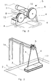
- FIG. 1 shows a basin 1 filled with a liquid 2, such as a swimming and leisure pool filled with water.
- Pool 1 can be rectangular or round, or any other form.
- a shell 3 is suspended within the pool 1 by a connecting means 4 which can be a cable, a strap, rope or chain.
- a winch 5 comprises a drum 6 on which the means link 4 can be wound, and an electric motor 7.
- Des pool water 1 periodic oscillations 1 are obtained by imposing a vertical reciprocating movement of the hull 3 in phase with the waves.
- the period of this movement vertical alternative is determined experimentally from so as to excite a proper oscillation mode of the mass of water in the pool.
- the amplitude of this movement alternative is determined so as to get waves of the desired amplitude.
- the shell can be made of a light material, little expensive, and water resistant, such as polyester reinforced glass fibers.
- a shape elongated rectangular is interesting in a swimming pool rectangular, and easily provides various modes transverse, longitudinal or combined oscillation of the water.
- a shell 3 with vertical side walls; and thoroughly horizontal promotes the transfer to the liquid of movements vertical, and limits the turbulence generated by horizontal movements.
- the angles of the shell 3 will be rounded.
- a control and regulation unit 8 can be placed near the engine, or moved to a convenient location and accessible. This box allows the operator to introduce the desired values of the reciprocating period vertical imposed on hull 3, and the amplitude of the waves at produce.
- the drum 6 includes a sensor 9 making it possible to measure its angular position, and deduce both the height from which the shell 3 is suspended and the speed of it.
- a blocking brake 11 keeps the hull 3 in the raised position when the device is not used.
- a reduction gear 10 adapts the rotation speed of the electric motor 7 at the desired speed for the drum 6. This reducer 10 transfers the torque to the drum engine during hull rise, and allows the drum to turn in the opposite direction when lowering the shell.
- the shell 3 is advantageously provided with at least one hole 12 so that the water 2 from the pool can enter the within the shell 3.
- the shell can be filled from above.
- the water contained in the shell 3 gives the whole a mass which allows it, after being lifted by winch 5, to descend under the effect of its weight apparent.
- the addition of buoyancy elements 13 allows to obtain that the hull, once submerged in the swimming pool, retains the ability to float. However, this is not at all necessary, and leaky hulls may be carried out without departing from the scope of the invention.
- Holes 12 allow the shell 3 to cling to the liquid 2 for good stir it. They also prevent excessive movement of the shell 3 relative to the liquid 2.
- the position of the shell 3 and the period of the movements alternatives imposed on it are determined experimentally so as to excite a mode of oscillation clean from pool 1, so as to get waves from the desired shape.
- the excitement of one of the oscillation modes clean of the basin allows to obtain waves in the form standing waves, comprising nodes and bellies in fixed points in the pool, without energy input important.
- the shell 3 is preferably placed in the vicinity of a belly of the desired oscillation mode. Movements of a particle of water in the vicinity of such a belly of the mode pool's own swing are mainly vertical.
- the shell 3 preferably has walls vertical side, so that it does not impose on water surrounding movements with a horizontal component, which are not part of the desired oscillation mode, and are therefore a source of energy dissipation.
- the motor 7 is preferably a current motor continuous and low voltage, meeting safety standards that apply to swimming pools. However, it can also be an AC motor or a pneumatic motor or hydraulic.
- the motor current regulation is provided by the control and regulation box 8.
- This control and regulation unit 8 makes it possible to determine the range of motion you want. It contains a regulator, for example of proportional-integral type, allowing the regulation of the current in the motor during the traction periods on the hull, in order to obtain the waves of desired amplitude.
- the amplitude of the waves actually obtained can be inferred from the movements of the shell 3. In fact, it moves little with respect to the liquid surface. The movement of the shell 3 is determined by measuring the angular position of the drum.
- the control and regulation unit 8 can also regulate the traction times and no traction on the hull.
- the pulling time is substantially equal to the duration of absence of traction.
- FIG. 2 represents an exemplary embodiment of the invention.
- a support structure 14 makes it possible to install the winch 5 above the surface of the pool 1.
- a such support structure 14 is required in open air swimming pools.
- a diving board can be used at title of support structure 14.
- Hull 3 is rectangular. Its length is 3 m and is oriented parallel to the side of a rectangular swimming pool 1.
- the width of hull 3 is 0.75 m.
- the weight of the hull is 45 kg.
- the shell 3 is provided with a protective cover pointed or curved, high enough so that swimmers do not can't grab onto it or settle in.
- Way to link 4 is a set of two belts fixed in points located on either side of the protective cover. This gives good stability to the shell 3.
- the winch mechanism 5 specific to this application is shown in Figure 3. It includes a return pulley 15 free to rotate around a horizontal axis, and a drum 6 integral with the output shaft of the electric motor 7 or its reducer 10, on which are wound, superimposed, the two belts 4.
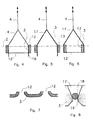
- Figures 4, 5 and 6 show variants of the shell of a device according to the invention.
- the shell shown in Figure 4 has a number important of 12 holes in its horizontal bottom.
- these holes have a profile such as that shown in Figure 7, which promotes the penetration of the water in the hull during its descent, and disadvantages the exit of the water during its rise. Therefore, the water level in the hull 3, which varies at course of its alternative movements, is established at a higher level than it would have in the absence of such profile.
- the hull is, in average value, deeper into the water. this allows apply a higher tensile force to the hull, without risk extracting it from water.
- the side faces of the shell 3 are extended downwards by fins 16. These drifts 16 accentuate the suction effect during the upward movement.
- the shell shown in Figure 5 has a open bottom, and is bell-shaped, open from the bottom and closed from above.
- the upper part of this bell has one or more air passage openings 17.
- this or these passage openings air 17 are provided with a valve as shown in Figure 8.
- the locking ball 18 lifts and allows the air to exit when the hull is lowered. When it goes up, said ball 18 applies in his seat.
- Said seat is provided with grooves 19, so that an air flow is still admitted during the mounting of the hull 3. In a manner analogous to the description above, this favors the exit of air and the penetration of the water in the hull during its descent, and disadvantages the entry of air and the exit of water during rise of it.
- the water level in the shell 3 which varies during the reciprocating movements of this, is established at a level higher than that which would have in the absence of such a valve. It results from even that the shell 3 is, in average value, pressed more deep in the water. This also allows you to apply to the shell a higher pulling force, without risking to extract it from the water.
- FIG. 6 represents a shell 3 having both the characteristics of the hulls represented in FIGS. 4 and 5, namely a perforated bottom, and a top shaped bet bell.
- the drifts were not planned, for security reasons.
- the device according to the invention can easily be installed in an existing swimming pool, without modifying its infrastructure.
- the winch 5 and its control box can be fixed to the pool ceiling.
- a structure 14 comprising a pole allows the shell 3 to be suspended at an appropriate point of the pelvis 1.
Landscapes
- Engineering & Computer Science (AREA)
- Architecture (AREA)
- Civil Engineering (AREA)
- Structural Engineering (AREA)
- Other Liquid Machine Or Engine Such As Wave Power Use (AREA)
- Toys (AREA)
- Structures Of Non-Positive Displacement Pumps (AREA)
Description
- la dite coque restant au moins partiellement immergée dans le liquide et remplie du liquide au cours de ces mouvements alternatifs.
Claims (15)
- Dispositif de création de vagues périodiques dans un liquide (2) contenu dans un bassin (1) tel qu'une piscine, comprenant un corps destiné à être immergé au moins partiellement dans le liquide ou à la surface de celui-ci et des organes destinés à provoquer un mouvement alternatif vertical de ce corps, le corps étant une coque (3) creuse comprenant un fond horizontal et des parois latérales en substance verticales et étant destinée à être remplie au moins partiellement du dit liquide caractérisé en ce que la dite coque (3) est destinée à être suspendue par un moyen de liaison (4) flexible à un moyen apte à exécuter périodiquement l'action de soulever verticalement la dite coque (3) pendant une durée donnée puis de la laisser redescendre pour engendrer les dites vagues périodiques, la dite coque étant destinée à rester au moins partiellement immergée dans le liquide et remplie du liquide au cours de ces mouvements alternatifs, lesdits moyens constituant lesdits organes du dispositif.
- Dispositif suivant la revendication 1, caractérisé en ce que la coque (3) comprend au moins un trou (12) permettant la pénétration du liquide (2) dans la coque (3).
- Dispositif suivant l'une quelconque des revendications précédentes, caractérisé en ce que la coque (3) comprend un élément de flottaison (13).
- Dispositif suivant l'une quelconque des revendications précédentes, caractérisé en ce que la coque (3) comprend un fond muni d'une pluralité de trous (12).
- Dispositif suivant la revendication 4, caractérisé en ce que les trous (12) sont aptes à favoriser la pénétration du liquide (2) dans la coque (3), et à en défavoriser la sortie.
- Dispositif suivant l'une quelconque des revendications précédentes, caractérisé en ce que la coque (3) comprend une partie supérieure en forme de cloche, munie d'au moins une ouverture de passage de l'air (17).
- Dispositif suivant la revendication 6, caractérisé en ce que une ouverture de passage de l'air (17) est apte à favoriser la sortie de l'air situé à la partie supérieure de la coque (3), et à en défavoriser l'entrée.
- Dispositif suivant l'une quelconque des revendications précédentes, caractérisé en ce que le moyen apte à exécuter périodiquement l'action de soulever verticalement la dite coque(3) pendant une durée donnée puis de la laisser redescendre pour engendrer les dites vagues périodiques, comprend un treuil (5) destiné à enrouler et à dérouler le moyen de liaison ( 4) flexible.
- Dispositif suivant la revendication 8, caractérisé en ce que le treuil (5) comprend un boítier de régulation (8) apte à régler la période d'enroulement et de déroulement du dit treuil (5).
- Dispositif suivant l'une quelconque des revendication 8 et 9, caractérisé en ce que le treuil (5) comporte un boítier de régulation (8) apte à régler le couple moteur de celui-ci.
- Procédé de création de vagues périodiques dans un liquide (2) contenu dans un bassin (1) tel qu'une piscine, au moyen du dispositif d'une des revendications 1 à 10, caractérisé en ce qu'il comprend les opérations suivantes :on suspend la coque (3) creuse par le moyen de liaison flexible (4) en un point du bassin (1), au sein du liquide ou à la surface de celui-ci la dite coque (3) étant au moins partiellement immergée dans le liquide (2) et remplie du liquide (2)on exécute périodiquement l'action de soulever la dite coque (3) pendant une durée donnée puis de la laisser redescendre par l'intermédiaire du dit moyen de liaison flexible, pour engendrer les dites vagues périodiques,la dite coque restant au moins partiellement immergée dans le liquide et remplie du liquide au cours de ces mouvements alternatifs.
- Procédé suivant la revendication 11 caractérisé en ce que le moyen apte à exécuter périodiquement l'action de soulever verticalement la dite coque(3) pendant une durée donnée puis de la laisser redescendre pour engendrer les dites vagues périodiques, comprend un treuil (5) destiné à enrouler et a dérouler le moyen de liaison ( 4) flexible.
- Procédé suivant l'une quelconque des revendications 11 et 12 caractérisé en ce qu'on détermine la périodicité des mouvements imposés à là coque (3) de manière à exciter une fréquence propre d'oscillation du liquide (2) contenu dans le bassin (1) .
- Procédé suivant l'une quelconque des. revendication 12 ou 13, caractérisé en ce qu'on détermine le couple moteur appliqué au treuil (5) pendant la durée de soulèvement de la coque (3) de manière à obtenir des vagues de l'amplitude souhaitée.
- Procédé suivant l'une quelconque des revendications 12 à 14, caractérisé en ce qu'on détermine le couple appliqué au treuil (5) pendant la durée de descente de la coque (3) de manière à maintenir en permanence le moyen de liaison flexible (4) sous tension.
Applications Claiming Priority (3)
| Application Number | Priority Date | Filing Date | Title |
|---|---|---|---|
| BE9700304 | 1997-04-03 | ||
| BE9700304A BE1011083A6 (fr) | 1997-04-03 | 1997-04-03 | Generateur de vagues pour liquides. |
| PCT/BE1998/000046 WO1998045553A1 (fr) | 1997-04-03 | 1998-04-02 | Generateur de vagues pour liquides |
Publications (2)
| Publication Number | Publication Date |
|---|---|
| EP0972122A1 EP0972122A1 (fr) | 2000-01-19 |
| EP0972122B1 true EP0972122B1 (fr) | 2004-02-11 |
Family
ID=3890443
Family Applications (1)
| Application Number | Title | Priority Date | Filing Date |
|---|---|---|---|
| EP98913458A Expired - Lifetime EP0972122B1 (fr) | 1997-04-03 | 1998-04-02 | Dispositif de création de vagues périodiques dans un bassin |
Country Status (7)
| Country | Link |
|---|---|
| US (1) | US6217256B1 (fr) |
| EP (1) | EP0972122B1 (fr) |
| AU (1) | AU6815398A (fr) |
| BE (1) | BE1011083A6 (fr) |
| DE (1) | DE69821606T2 (fr) |
| ES (1) | ES2217543T3 (fr) |
| WO (1) | WO1998045553A1 (fr) |
Families Citing this family (16)
| Publication number | Priority date | Publication date | Assignee | Title |
|---|---|---|---|---|
| US6762090B2 (en) * | 2001-09-13 | 2004-07-13 | Hynix Semiconductor Inc. | Method for fabricating a capacitor |
| DE102004023708A1 (de) * | 2004-05-11 | 2005-12-15 | Tunze Aquarientechnik Gmbh | Verfahren und Vorrichtung zum Erzeugen von Wellen in einem Aquarienbehälter |
| DE102010035117B4 (de) | 2010-08-23 | 2012-06-06 | Falko Müller | Anlage und Verfahren zum Erzeugen von Wellen |
| DE102011016842B3 (de) * | 2011-04-12 | 2012-09-06 | Falko Müller | Anlage und Verfahren zum Erzeugen von Fortschreitenden Wasserwellen |
| DE102013016307B3 (de) * | 2013-09-12 | 2015-02-19 | Falko Müller | Anlage und Verfahren zur Erzeugung von kontinuierlichen Wasserwellen |
| PE20170237A1 (es) * | 2014-06-08 | 2017-04-05 | Surf Lakes Holdings Ltd | Generacion de olas de surfeo |
| CN105509995B (zh) * | 2015-11-24 | 2018-05-15 | 中山大学 | 基于垂向多层控制的内波造波系统及其控制方法 |
| US9920544B1 (en) * | 2016-11-29 | 2018-03-20 | Walter Judson Bennett | Plunger wave generator apparatus for efficiently producing waves in a body of water |
| JP2020507701A (ja) * | 2016-12-23 | 2020-03-12 | グランサム,ピーター | 水域内で波を発生させるための組立体及び方法 |
| US10519679B1 (en) | 2018-08-31 | 2019-12-31 | Walter Judson Bennett | Plunger artificial wave making apparatus |
| CN111395817A (zh) * | 2020-04-02 | 2020-07-10 | 何厚煌 | 人工造浪装置及人工造浪方法 |
| CN111441306B (zh) * | 2020-04-20 | 2021-10-08 | 水利部交通运输部国家能源局南京水利科学研究院 | 一种水动力提升方法及其性能测试方法 |
| CN111501657B (zh) * | 2020-04-20 | 2021-10-08 | 水利部交通运输部国家能源局南京水利科学研究院 | 一种基于人工造浪的水动力提升装置及其性能测试方法 |
| CN111957278B (zh) * | 2020-09-11 | 2025-01-03 | 成都善哲诚自动化技术有限公司 | 一种药品合成设备 |
| US11686116B2 (en) * | 2021-05-18 | 2023-06-27 | Walter Judson Bennett | Plunger wave making generator system |
| ES2957222B2 (es) * | 2022-06-01 | 2024-06-05 | Martinez Rafael Marco | Sistema generador de olas |
Citations (3)
| Publication number | Priority date | Publication date | Assignee | Title |
|---|---|---|---|---|
| US3973405A (en) * | 1974-11-20 | 1976-08-10 | Societe Generale De Constructions Electriques Et Mecaniques (Alsthom) | Surge generators of the plunger type |
| US4276664A (en) * | 1979-01-30 | 1981-07-07 | Baker William H | Apparatus for wave-making |
| US4507018A (en) * | 1982-06-24 | 1985-03-26 | Andersen Per F | Wave making machines |
Family Cites Families (8)
| Publication number | Priority date | Publication date | Assignee | Title |
|---|---|---|---|---|
| GB409236A (en) * | 1933-11-20 | 1934-04-26 | Georg Recknagel | Improvements in or relating to apparatus for the production of waves in liquids |
| US3789612A (en) * | 1972-03-27 | 1974-02-05 | G Richard | Method of surf generation |
| CA1247382A (fr) * | 1985-03-08 | 1988-12-28 | Per F. Andersen | Generateur d'ondes en surface d'un plan d'eau |
| FR2602012B1 (fr) | 1985-12-11 | 1988-10-07 | Principia Rech Dev | Generateur de houle |
| US4810129A (en) | 1986-12-04 | 1989-03-07 | Principia Recherche Developpement S.A. | Arrangement for generating waves in a body of water |
| BE1003170A3 (fr) | 1990-03-15 | 1991-12-17 | Wow Company | Dispositif pour creer un mouvement a la surface d'un liquide. |
| US5621925A (en) | 1995-03-03 | 1997-04-22 | Bastenhof; Dirk | Pool or water tank, such as a swimming pool, provided with means generating waves |
| EP0732468B1 (fr) | 1995-03-03 | 1999-01-20 | Dirk Bastenhof | Bassin ou réservoir d'eau, tel qu'une piscine, avec des moyens générateurs de vagues |
-
1997
- 1997-04-03 BE BE9700304A patent/BE1011083A6/fr not_active IP Right Cessation
-
1998
- 1998-04-02 WO PCT/BE1998/000046 patent/WO1998045553A1/fr not_active Ceased
- 1998-04-02 AU AU68153/98A patent/AU6815398A/en not_active Abandoned
- 1998-04-02 EP EP98913458A patent/EP0972122B1/fr not_active Expired - Lifetime
- 1998-04-02 ES ES98913458T patent/ES2217543T3/es not_active Expired - Lifetime
- 1998-04-02 DE DE69821606T patent/DE69821606T2/de not_active Expired - Lifetime
-
1999
- 1999-09-21 US US09/401,002 patent/US6217256B1/en not_active Expired - Fee Related
Patent Citations (3)
| Publication number | Priority date | Publication date | Assignee | Title |
|---|---|---|---|---|
| US3973405A (en) * | 1974-11-20 | 1976-08-10 | Societe Generale De Constructions Electriques Et Mecaniques (Alsthom) | Surge generators of the plunger type |
| US4276664A (en) * | 1979-01-30 | 1981-07-07 | Baker William H | Apparatus for wave-making |
| US4507018A (en) * | 1982-06-24 | 1985-03-26 | Andersen Per F | Wave making machines |
Also Published As
| Publication number | Publication date |
|---|---|
| US6217256B1 (en) | 2001-04-17 |
| DE69821606T2 (de) | 2005-01-05 |
| WO1998045553A1 (fr) | 1998-10-15 |
| DE69821606D1 (de) | 2004-03-18 |
| BE1011083A6 (fr) | 1999-04-06 |
| EP0972122A1 (fr) | 2000-01-19 |
| AU6815398A (en) | 1998-10-30 |
| ES2217543T3 (es) | 2004-11-01 |
Similar Documents
| Publication | Publication Date | Title |
|---|---|---|
| EP0972122B1 (fr) | Dispositif de création de vagues périodiques dans un bassin | |
| FR2823485A1 (fr) | Dispositif de mise a l'eau et de recuperation d'un vehicule sous-marin et procede de mise en oeuvre | |
| EP0104983B1 (fr) | Nacelle | |
| EP0942102B1 (fr) | Plate-forme auto-élévatrice à réservoir immergé et procédés de mise en place et de relevage du réservoir | |
| CA1091046A (fr) | Methode pour immerger un dispositif de flottabilite negative | |
| FR2577510A1 (fr) | Bateau de transbordement vertical et horizontal | |
| FR3042548A1 (fr) | Systeme de stockage et generation d'energie electrique pour milieu aquatique et subaquatique | |
| JPH10140536A (ja) | 水中マット布設用架台と水中マット布設方法 | |
| FR2480861A1 (en) | Continuous water energy converter - uses chain of spherical floats passing over wheels above and below water to convert vertical float chain movement to rotation | |
| WO2004070165A1 (fr) | Dispositif de collecte de produit et/ou de tranquillisation d'une colonne en milieu sous-marin et son utilisation | |
| FR2981380A1 (fr) | Piscine a plancher mobile | |
| WO2008104712A1 (fr) | Dispositif d'ancrage semi permanent/permanent destine a amarrer des corps flottants | |
| US20080146103A1 (en) | Protection of apparatus for capturing wave energy | |
| EP3707371B1 (fr) | Centrale hydroelectrique flottante pour rivieres peu profondes | |
| EP0137087A1 (fr) | Procédé de mytiliculture et installation et flotteurs pour sa mise en oeuvre | |
| FR2545439A1 (fr) | Dispositif d'amarrage | |
| EP2441902A1 (fr) | Fond mobile pour piscine | |
| JP6443687B2 (ja) | ワイヤ張力調整装置 | |
| JP2013155508A (ja) | 網場、及びその設置構造 | |
| FR2544446A1 (fr) | Procede pour realiser les atterrissages d'arrivee de cables sous-marins | |
| FR2518519A1 (fr) | Dispositif elevateur adaptable notamment sur les grues a tour, en vue de faciliter le hissage et la descente du grutier | |
| FR2813578A1 (fr) | Dispositif de mouillage | |
| EP2585640B1 (fr) | Dispositif et systeme de protection contre l'erosion du littoral | |
| CA2193266C (fr) | Barriere marine antipollution | |
| RU2370406C1 (ru) | Подводное спуско-подъемное устройство |
Legal Events
| Date | Code | Title | Description |
|---|---|---|---|
| PUAI | Public reference made under article 153(3) epc to a published international application that has entered the european phase |
Free format text: ORIGINAL CODE: 0009012 |
|
| 17P | Request for examination filed |
Effective date: 19990924 |
|
| AK | Designated contracting states |
Kind code of ref document: A1 Designated state(s): BE DE ES FR GB IT NL |
|
| 17Q | First examination report despatched |
Effective date: 20011206 |
|
| GRAP | Despatch of communication of intention to grant a patent |
Free format text: ORIGINAL CODE: EPIDOSNIGR1 |
|
| RTI1 | Title (correction) |
Free format text: DEVICE FOR GENERATING PERIODIC WAVES IN A BASIN |
|
| RTI1 | Title (correction) |
Free format text: DEVICE FOR GENERATING PERIODIC WAVES IN A BASIN |
|
| GRAS | Grant fee paid |
Free format text: ORIGINAL CODE: EPIDOSNIGR3 |
|
| GRAA | (expected) grant |
Free format text: ORIGINAL CODE: 0009210 |
|
| AK | Designated contracting states |
Kind code of ref document: B1 Designated state(s): BE DE ES FR GB IT NL |
|
| REG | Reference to a national code |
Ref country code: GB Ref legal event code: FG4D Free format text: NOT ENGLISH |
|
| REF | Corresponds to: |
Ref document number: 69821606 Country of ref document: DE Date of ref document: 20040318 Kind code of ref document: P |
|
| GBT | Gb: translation of ep patent filed (gb section 77(6)(a)/1977) |
Effective date: 20040416 |
|
| REG | Reference to a national code |
Ref country code: ES Ref legal event code: FG2A Ref document number: 2217543 Country of ref document: ES Kind code of ref document: T3 |
|
| PLBE | No opposition filed within time limit |
Free format text: ORIGINAL CODE: 0009261 |
|
| STAA | Information on the status of an ep patent application or granted ep patent |
Free format text: STATUS: NO OPPOSITION FILED WITHIN TIME LIMIT |
|
| 26N | No opposition filed |
Effective date: 20041112 |
|
| PG25 | Lapsed in a contracting state [announced via postgrant information from national office to epo] |
Ref country code: IT Free format text: LAPSE BECAUSE OF NON-PAYMENT OF DUE FEES Effective date: 20050402 |
|
| PGFP | Annual fee paid to national office [announced via postgrant information from national office to epo] |
Ref country code: GB Payment date: 20090423 Year of fee payment: 12 |
|
| PGFP | Annual fee paid to national office [announced via postgrant information from national office to epo] |
Ref country code: FR Payment date: 20100426 Year of fee payment: 13 Ref country code: ES Payment date: 20100428 Year of fee payment: 13 |
|
| PGFP | Annual fee paid to national office [announced via postgrant information from national office to epo] |
Ref country code: NL Payment date: 20100428 Year of fee payment: 13 Ref country code: DE Payment date: 20100428 Year of fee payment: 13 |
|
| GBPC | Gb: european patent ceased through non-payment of renewal fee |
Effective date: 20100402 |
|
| PG25 | Lapsed in a contracting state [announced via postgrant information from national office to epo] |
Ref country code: GB Free format text: LAPSE BECAUSE OF NON-PAYMENT OF DUE FEES Effective date: 20100402 |
|
| REG | Reference to a national code |
Ref country code: DE Ref legal event code: R119 Ref document number: 69821606 Country of ref document: DE |
|
| REG | Reference to a national code |
Ref country code: DE Ref legal event code: R119 Ref document number: 69821606 Country of ref document: DE |
|
| REG | Reference to a national code |
Ref country code: NL Ref legal event code: V1 Effective date: 20111101 |
|
| REG | Reference to a national code |
Ref country code: FR Ref legal event code: ST Effective date: 20111230 |
|
| PG25 | Lapsed in a contracting state [announced via postgrant information from national office to epo] |
Ref country code: FR Free format text: LAPSE BECAUSE OF NON-PAYMENT OF DUE FEES Effective date: 20110502 Ref country code: NL Free format text: LAPSE BECAUSE OF NON-PAYMENT OF DUE FEES Effective date: 20111101 |
|
| REG | Reference to a national code |
Ref country code: ES Ref legal event code: FD2A Effective date: 20120524 |
|
| PG25 | Lapsed in a contracting state [announced via postgrant information from national office to epo] |
Ref country code: ES Free format text: LAPSE BECAUSE OF NON-PAYMENT OF DUE FEES Effective date: 20110403 |
|
| PG25 | Lapsed in a contracting state [announced via postgrant information from national office to epo] |
Ref country code: DE Free format text: LAPSE BECAUSE OF NON-PAYMENT OF DUE FEES Effective date: 20111031 |
|
| PGFP | Annual fee paid to national office [announced via postgrant information from national office to epo] |
Ref country code: BE Payment date: 20130422 Year of fee payment: 16 |
|
| PG25 | Lapsed in a contracting state [announced via postgrant information from national office to epo] |
Ref country code: BE Free format text: LAPSE BECAUSE OF NON-PAYMENT OF DUE FEES Effective date: 20140430 |
|
| P01 | Opt-out of the competence of the unified patent court (upc) registered |
Effective date: 20230510 |