EP0972333B1 - Verfahren und systeme zum verbesserten flüssigkeitstransport - Google Patents
Verfahren und systeme zum verbesserten flüssigkeitstransport Download PDFInfo
- Publication number
- EP0972333B1 EP0972333B1 EP98913300A EP98913300A EP0972333B1 EP 0972333 B1 EP0972333 B1 EP 0972333B1 EP 98913300 A EP98913300 A EP 98913300A EP 98913300 A EP98913300 A EP 98913300A EP 0972333 B1 EP0972333 B1 EP 0972333B1
- Authority
- EP
- European Patent Office
- Prior art keywords
- fluid
- discrete
- volumes
- channels
- volume
- Prior art date
- Legal status (The legal status is an assumption and is not a legal conclusion. Google has not performed a legal analysis and makes no representation as to the accuracy of the status listed.)
- Expired - Lifetime
Links
Images

Classifications
-
- B—PERFORMING OPERATIONS; TRANSPORTING
- B01—PHYSICAL OR CHEMICAL PROCESSES OR APPARATUS IN GENERAL
- B01L—CHEMICAL OR PHYSICAL LABORATORY APPARATUS FOR GENERAL USE
- B01L3/00—Containers or dishes for laboratory use, e.g. laboratory glassware; Droppers
- B01L3/50—Containers for the purpose of retaining a material to be analysed, e.g. test tubes
- B01L3/502—Containers for the purpose of retaining a material to be analysed, e.g. test tubes with fluid transport, e.g. in multi-compartment structures
- B01L3/5027—Containers for the purpose of retaining a material to be analysed, e.g. test tubes with fluid transport, e.g. in multi-compartment structures by integrated microfluidic structures, i.e. dimensions of channels and chambers are such that surface tension forces are important, e.g. lab-on-a-chip
- B01L3/502746—Containers for the purpose of retaining a material to be analysed, e.g. test tubes with fluid transport, e.g. in multi-compartment structures by integrated microfluidic structures, i.e. dimensions of channels and chambers are such that surface tension forces are important, e.g. lab-on-a-chip characterised by the means for controlling flow resistance, e.g. flow controllers, baffles or throttle valves
-
- B—PERFORMING OPERATIONS; TRANSPORTING
- B01—PHYSICAL OR CHEMICAL PROCESSES OR APPARATUS IN GENERAL
- B01D—SEPARATION
- B01D61/00—Processes of separation using semi-permeable membranes, e.g. dialysis, osmosis or ultrafiltration; Apparatus, accessories or auxiliary operations specially adapted therefor
- B01D61/42—Electrodialysis; Electro-osmosis ; Electro-ultrafiltration; Membrane capacitive deionization
- B01D61/56—Electro-osmotic dewatering
-
- B—PERFORMING OPERATIONS; TRANSPORTING
- B01—PHYSICAL OR CHEMICAL PROCESSES OR APPARATUS IN GENERAL
- B01L—CHEMICAL OR PHYSICAL LABORATORY APPARATUS FOR GENERAL USE
- B01L3/00—Containers or dishes for laboratory use, e.g. laboratory glassware; Droppers
- B01L3/50—Containers for the purpose of retaining a material to be analysed, e.g. test tubes
- B01L3/502—Containers for the purpose of retaining a material to be analysed, e.g. test tubes with fluid transport, e.g. in multi-compartment structures
- B01L3/5027—Containers for the purpose of retaining a material to be analysed, e.g. test tubes with fluid transport, e.g. in multi-compartment structures by integrated microfluidic structures, i.e. dimensions of channels and chambers are such that surface tension forces are important, e.g. lab-on-a-chip
- B01L3/50273—Containers for the purpose of retaining a material to be analysed, e.g. test tubes with fluid transport, e.g. in multi-compartment structures by integrated microfluidic structures, i.e. dimensions of channels and chambers are such that surface tension forces are important, e.g. lab-on-a-chip characterised by the means or forces applied to move the fluids
-
- G—PHYSICS
- G01—MEASURING; TESTING
- G01N—INVESTIGATING OR ANALYSING MATERIALS BY DETERMINING THEIR CHEMICAL OR PHYSICAL PROPERTIES
- G01N27/00—Investigating or analysing materials by the use of electric, electrochemical, or magnetic means
- G01N27/26—Investigating or analysing materials by the use of electric, electrochemical, or magnetic means by investigating electrochemical variables; by using electrolysis or electrophoresis
- G01N27/416—Systems
- G01N27/447—Systems using electrophoresis
- G01N27/44704—Details; Accessories
- G01N27/44747—Composition of gel or of carrier mixture
-
- G—PHYSICS
- G01—MEASURING; TESTING
- G01N—INVESTIGATING OR ANALYSING MATERIALS BY DETERMINING THEIR CHEMICAL OR PHYSICAL PROPERTIES
- G01N27/00—Investigating or analysing materials by the use of electric, electrochemical, or magnetic means
- G01N27/26—Investigating or analysing materials by the use of electric, electrochemical, or magnetic means by investigating electrochemical variables; by using electrolysis or electrophoresis
- G01N27/416—Systems
- G01N27/447—Systems using electrophoresis
- G01N27/44704—Details; Accessories
- G01N27/44752—Controlling the zeta potential, e.g. by wall coatings
-
- B—PERFORMING OPERATIONS; TRANSPORTING
- B01—PHYSICAL OR CHEMICAL PROCESSES OR APPARATUS IN GENERAL
- B01J—CHEMICAL OR PHYSICAL PROCESSES, e.g. CATALYSIS OR COLLOID CHEMISTRY; THEIR RELEVANT APPARATUS
- B01J2219/00—Chemical, physical or physico-chemical processes in general; Their relevant apparatus
- B01J2219/00781—Aspects relating to microreactors
- B01J2219/00851—Additional features
- B01J2219/00853—Employing electrode arrangements
-
- B—PERFORMING OPERATIONS; TRANSPORTING
- B01—PHYSICAL OR CHEMICAL PROCESSES OR APPARATUS IN GENERAL
- B01J—CHEMICAL OR PHYSICAL PROCESSES, e.g. CATALYSIS OR COLLOID CHEMISTRY; THEIR RELEVANT APPARATUS
- B01J2219/00—Chemical, physical or physico-chemical processes in general; Their relevant apparatus
- B01J2219/00781—Aspects relating to microreactors
- B01J2219/00891—Feeding or evacuation
-
- B—PERFORMING OPERATIONS; TRANSPORTING
- B01—PHYSICAL OR CHEMICAL PROCESSES OR APPARATUS IN GENERAL
- B01L—CHEMICAL OR PHYSICAL LABORATORY APPARATUS FOR GENERAL USE
- B01L2300/00—Additional constructional details
- B01L2300/08—Geometry, shape and general structure
- B01L2300/0809—Geometry, shape and general structure rectangular shaped
- B01L2300/0816—Cards, e.g. flat sample carriers usually with flow in two horizontal directions
-
- B—PERFORMING OPERATIONS; TRANSPORTING
- B01—PHYSICAL OR CHEMICAL PROCESSES OR APPARATUS IN GENERAL
- B01L—CHEMICAL OR PHYSICAL LABORATORY APPARATUS FOR GENERAL USE
- B01L2400/00—Moving or stopping fluids
- B01L2400/04—Moving fluids with specific forces or mechanical means
- B01L2400/0403—Moving fluids with specific forces or mechanical means specific forces
- B01L2400/0415—Moving fluids with specific forces or mechanical means specific forces electrical forces, e.g. electrokinetic
- B01L2400/0418—Moving fluids with specific forces or mechanical means specific forces electrical forces, e.g. electrokinetic electro-osmotic flow [EOF]
-
- B—PERFORMING OPERATIONS; TRANSPORTING
- B01—PHYSICAL OR CHEMICAL PROCESSES OR APPARATUS IN GENERAL
- B01L—CHEMICAL OR PHYSICAL LABORATORY APPARATUS FOR GENERAL USE
- B01L2400/00—Moving or stopping fluids
- B01L2400/04—Moving fluids with specific forces or mechanical means
- B01L2400/0403—Moving fluids with specific forces or mechanical means specific forces
- B01L2400/0415—Moving fluids with specific forces or mechanical means specific forces electrical forces, e.g. electrokinetic
- B01L2400/0421—Moving fluids with specific forces or mechanical means specific forces electrical forces, e.g. electrokinetic electrophoretic flow
-
- B—PERFORMING OPERATIONS; TRANSPORTING
- B01—PHYSICAL OR CHEMICAL PROCESSES OR APPARATUS IN GENERAL
- B01L—CHEMICAL OR PHYSICAL LABORATORY APPARATUS FOR GENERAL USE
- B01L2400/00—Moving or stopping fluids
- B01L2400/08—Regulating or influencing the flow resistance
- B01L2400/084—Passive control of flow resistance
-
- Y—GENERAL TAGGING OF NEW TECHNOLOGICAL DEVELOPMENTS; GENERAL TAGGING OF CROSS-SECTIONAL TECHNOLOGIES SPANNING OVER SEVERAL SECTIONS OF THE IPC; TECHNICAL SUBJECTS COVERED BY FORMER USPC CROSS-REFERENCE ART COLLECTIONS [XRACs] AND DIGESTS
- Y10—TECHNICAL SUBJECTS COVERED BY FORMER USPC
- Y10S—TECHNICAL SUBJECTS COVERED BY FORMER USPC CROSS-REFERENCE ART COLLECTIONS [XRACs] AND DIGESTS
- Y10S366/00—Agitating
- Y10S366/02—Micromixers: segmented laminar flow with boundary mixing orthogonal to the direction of fluid propagation with or without geometry influences from the pathway
Definitions
- CE systems generally employ fused silica capillaries, or more recently, etched channels in planar silica substrates, filled with an appropriate separation matrix or medium.
- a sample fluid that is to be analyzed is injected at one end of the capillary or channel.
- Application of a voltage across the capillary then permits the electrophoretic migration of the species within the sample.
- Differential electrophoretic mobilities of the constituent elements of a sample fluid e.g., due to their differential net charge or size, permits their separation, identification and analysis.
- non-CE fluidic systems differ from the CE systems in that their goal is not the electrophoretic separation of constituents of a sample or fluid, but is instead directed to the bulk transport of fluids and the materials contained in those fluids.
- these non-CE fluidic systems have relied upon mechanical fluid direction and transport systems, e.g., miniature pumps and valves, to affect material transport from one location to another. See, e.g., Published PCT Application WO 97/02357.
- mechanical systems can be extremely difficult and expensive to produce, and still fail to provide accurate fluidic control over volumes that are substantially below the microliter range.
- Electroosmotic (E/O) flow systems have been described which provide a substantial improvement over these mechanical systems, see, e.g., Published PCT Application No. WO 96/04547 to Ramsey et al.
- E/O Electroosmotic flow systems
- Such systems function by applying a voltage across a fluid filled channel, the surface or walls of which have charged or ionizeable functional groups associated therewith, to produce electroosmotic flow of that fluid in the direction of the current.
- electroosmotic fluid direction systems there remains ample room for improvement in the application of these technologies.
- the present invention meets these and other needs.
- the present invention generally provides methods and systems which provide for enhanced transportation and direction of materials using electroosmotic flow of a fluid containing those materials.
- the present invention provides methods of enhancing material transport by electroosmotic flow as set out in claim 1.
- the present invention also provides methods of transporting at least first and second discrete fluid volumes along a fluid filled channel as set out in claim 12.
- microfluidic systems as set out in claim 17 which incorporate these enhanced fluid direction and transport methods, i.e., provide for such enhanced fluid transport and direction within a microscale fluid channel structure.
- these microfluidic systems include at least three ports disposed at the termini of at least two intersecting fluid channels capable of supporting electroosmotic flow.
- at least one of the intersecting channels has at least one cross-sectional dimension of from about 0.1 ⁇ m to about 500 ⁇ m.
- Each of the ports may include an electrode placed in electrical contact with it, and the system also includes a fluid disposed in the channels, whereby the fluid is in electrical contact with those electrodes, and wherein the fluid comprises an effective concentration of a zwitterionic compound.
- the present invention generally provides methods and systems for the enhanced transportation and direction of materials within fluidic systems, which utilizes the electroosmotic flow of fluids containing those materials.
- enhanced transportation and direction is generally meant the electroosmotic flow and direction of fluids wichin fluidic systems, which shows: (1) a reduction in the electrophoretic mobility of a charged species relative to the electroosmotic flow of the fluid containing that charged species; and/or (2) an increase in the overall electroosmotic flow of that fluid, relative to such systems not incorporating the present invention, as described herein.
- the general goal is to maximize the separation between different species contained in a sample of interest, in order to separately analyze those species, identify their presence within the sample, or the like. This is accomplished by maximizing the differences in the electrophoretic mobilities of these species, which differences may result from differences in their size and/or net charge.
- E/O fluid direction systems In the E/O fluid direction systems described herein, however, the goals are somewhat different from those of CE systems.
- the general object of these E/O fluid direction systems is the transport and/or direction of material of interest contained in a volume of fluid or multiple discrete volumes of fluid, from one location in the system to another, using controlled E/O flow. Because these fluids are generally to be subjected to further manipulation or combination with other fluids, it is generally desirable to affect the transportation of these fluids without substantially altering their make-up, i.e., electrophoretically separating or biasing differentially charged or sized materials contained within those fluids.
- the improved coherency of a particular fluid volume within the E/O flow system permits the transport of larger numbers of different fluid volumes per unit time. Specifically, maintaining higher fluid volume coherency allows separate volumes to be transported closer together through the channels of the system, without resulting in excessive intermixing of these volumes. Further, maintenance of maximum fluid volume coherency during the transport and direction of the fluids permits more precise control of volumetric delivery of materials within these systems.
- the application of an electrical field across a fluid of interest has the same basic result.
- the fluid of interest comprises charged species, or is made up or a plurality of differentially charged chemical species
- application of a voltage across that fluid e.g., to obtain E/O flow
- those charged species electrophoresing within the fluid and the differentially charged species electrophoresing at different rates.
- negatively charged species will have an electrophoretic mobility opposite to the direction of E/O flow
- positively charged species will have an electrophoretic mobility in the same direction of E/O flow.
- this separation can result in an electrophoretic biasing of the sample, where the positively charged species have a greater apparent mobility, than negatively charged species.
- "Apparent mobility” as used herein generally refers to the overall mobility of a given species within the fluidic system. In the systems of the present invention, apparent mobility is typically defined as the rate of E/O mobility plus the electrophoretic mobility. Where electrophoretic mobility is opposite to the direction of E/O flow, i.e., negative, this leads to an apparent mobility that is less than the E/O mobility.
- species having high electrophoretic mobility e.g., highly charged species
- the effect can be magnified to the point that the apparent mobility of such species is substantially different from the E/O mobility of the fluid containing them.
- species possessing multiple negative charges may have an electrophoretic mobility substantially opposite the direction of E/O mobility, resulting in a substantial reduction in the apparent mobility of that species. Where that reduction is sufficiently large, it can result in that species being effectively "left behind" by the particular volume of fluid that is being transported.
- a species bearing multiple positive charges may have an apparent mobility that is far greater than that of the fluid being transported and other species contained therein, such that the species is transported well ahead of the fluid volume.
- This problem is not as significant where one is transporting large volumes of fluid from one location to another. Specifically, one can reduce the effects of the electrophoretic separation of a fluid by collecting larger volumes, thereby reducing the contribution that biased portions of the fluid have on the overall fluid delivered.
- the problem is substantially magnified when one wishes to transport a relatively small volume, or multiple small volumes of the same or different fluids, without separating the materials contained in the individual fluid volumes or intermixing the materials contained in separate volumes.
- a particular fluid or fluids e.g., samples, test compounds
- various elements of a screening system species that have apparent mobilities that are substantially different from the E/O mobility of the particular fluid volume will travel ahead of, and behind the fluid volume, effectively smearing the materials that are sought to be delivered.
- this is a significant disadvantage where relatively precise fluid control is desired, or where smaller effective volumes are used.
- a species in a first volume being transported has an apparent mobility that is substantially less than the E/O mobility of the fluid
- a species in a second or following volume has an apparent mobility that is substantially greater than the E/O mobility of the fluid that is being delivered
- those two species can overlap within the flow system.
- Figure 1A shows an optimal situation where discrete volumes or regions of fluids in a channel (fluids AB and XY, shown underlined) contain differentially charged species, e.g., X+ and Y-, and A+ and B-.
- these differentially charged chemical species have an apparent mobility that is not substantially different from the E/O mobility of the fluid containing those species.
- Figure 1B illustrates the smearing effect which results when charged species, as a result of their greater electrophoretic mobilities, begin to migrate outside of their respective fluid volumes or regions.
- Figure 1C illustrates the situation where the apparent mobility of the charged species is so substantially different from the E/O mobility of the fluid regions, that it results in the overlapping and intermixing of differentially charged species from different fluid regions.
- the intermixing of separate fluid volumes creates substantial problems where the fluid system is being used in the serial transport of multiple different fluids, e.g., as described in WO 98/00231.
- the enhanced E/O material transport and direction produced by the present invention is carried out by providing within the fluid component of the system, a compound or compounds that are capable of reducing the effects such an E/O system has on charged species contained within the fluid.
- incorporation of these compounds within the fluid component of the E/O flow system typically results in a reduction in the electrophoretic mobility of charged species, and thus, reduces the differential electrophoretic mobility and apparent mobility of differentially charged species.
- zwitterionic compounds or combinations thereof are used to reduce the electrophoretic mobility of materials that are contained within the fluids that are sought to be transported using these E/O fluid direction systems, thereby achieving or substantially achieving the optimal situation shown in Figure 1A.
- zwitterionic compounds interact with the charged species in a layer-like complex.
- the "complex” has the same net charge as the charged species, but that charge is spread over a much larger structure effectively reducing the charge:size ratio, and reducing the electrophoretic mobility of the complex. Because zwitterions are dipolar molecules, they can be effectively employed with respect to positively or negatively charged species.
- zwitterionic compounds as described herein is readily compatible with systems to be used for the transport of pH sensitive materials, e.g., systems used in analysis of biological systems.
- different zwitterionic compounds i.e.; having different pI, may be selected depending upon the pH sensitivity of the material being transported.
- the present invention is particularly useful in E/O fluid direction systems where the materials to be transported include biological material, such as enzymes, substrates, ligands, receptors, or other elements of biological or biochemical systems, e.g., as those systems are defined in WO 98/00231.
- fluorescein is a molecule that carries two negative charges above neutral pH.
- the electrophoretic mobility of this molecule can be readily altered by adding an antibody, such as anti-fluorescein to the solution.
- the resulting complex will have a substantially reduced electrophoretic mobility over that of fluorescein alone.
- a specifically associating compound must be identified for each charged molecular species in the fluid, and for each different fluid used in the system. Further, as is the case with the fluorescein/anti-fluorescein complex described above, incorporation of an active molecule into a larger complex can have an adverse effect on the desired activity or function of that molecule, i.e., substantially reduced fluorescence.
- the functions of zwitterionic compounds in reducing electrophoretic mobility of charged species is generally applicable, i.e., does not require a specific interaction between the charged species and the zwitterion. Further, the nature of this interaction results in little or no effect on the properties of the charged molecule of interest.
- incorporation of zwitterionic compounds in many systems can also have the effect of increasing the E/O mobility in the fluid direction system, thereby further optimizing the apparent mobility of the material that is being transported.
- zwitterionic and related chemical compounds may be employed according to the present invention.
- such compounds include, e.g., betaine, sulfobetaine, taurine, aminomethane sulfonic acid, zwitterionic amino acids, such as glycine, alanine, ⁇ -alanine, etc., and other zwitterionic compounds such as HEPES, MES, CAPS, tricine and the like.
- non-detergent, low molecular weight sulfobetaines are used in the methods of the present invention, such as dimethylethylaminopropane sulfonic acid, dimethylbenzylaminopropane sulfonic acid, and 3-(N-pyridinium)propane sulfonic acid.
- the concentration of zwitterionic compounds within the fluids contained in the system may be varied depending upon the effect desired, where lower concentrations yield less of an effect in reducing electrophoretic mobilities of materials contained within the fluid. Further, these effects may also be varied depending upon the nature of the charged species contained within the material of interest. Therefore, as used herein, the term “effective concentration” refers to a concentration of zwitterionic compounds that is sufficient to achieve a desired effect, and particularly, achieve some reduction in the electrophoretic mobility of a charged species of interest. Further, by “concentration” of zwitterionic compounds in the fluid” is meant the amount of such compounds added per unit volume, regardless of any subsequent conversion of such compounds within the fluid system.
- zwitterionic compounds typically be greater than about 5 mM, typically greater than about 10 mM, and often greater than about 50 mM.
- zwitterionic compounds may generally be present at levels approaching their solubility limits in practicing the present invention, preferred concentrations of the zwitterionic compounds in the fluid that is sought to be transported within the system will range between about 1 mM and 2M and more preferably between about 5mM and 2 M.
- E/O fluid direction systems is generally meant fluidic systems that are made up of fluid channels or passages, chambers, ports or the like, wherein the movement of fluid within the systems, i.e., through the channels, or from one channel to another channel, or from one chamber to another chamber, is selectively directed through the controlled electroosmotic flow of that fluid.
- Examples of such controlled E/O flow systems are described in, e.g., Published PCT Application No. WO 96/04547, WO98/00231 and US Patent No: 5,880,071.
- such fluid direction systems direct a fluid of interest through intersecting channel structures by applying a voltage gradient along the desired path of fluid flow.
- Voltages are typically simultaneously applied along the intersecting fluid paths, in order to propagate a containing or directing fluid flow, i.e., to contain or direct the fluid of interest along the desired path.
- the flow of the fluid of interest is maintained within the first channel, i.e., prevented from diffusing into the intersecting channel, by simultaneously flowing fluid into the first channel from each side of the intersecting channel.
- a fluid of interest may be directed from a first arm of a first channel into a first arm of an intersecting channel, by applying a voltage across the desired fluid flow path to generate fluid flow in that direction.
- a containing fluid flow is generated along the entire length of the intersecting channel creating what is termed a "gated" flow.
- the fluid of interest can then be metered out or dispensed in a controlled fashion, into the remaining arm of the first channel by actively modulating the voltage to allow the fluid to flow into that arm, while preventing diffusion. Effectively, this results in a valving system without the necessity of mechanical elements. Finally, by modulating the rate of flow of the fluid of interest through an intersection as compared to the flow of diluents flowing in from the intersecting channels, these systems can be used as diluters.
- microscale fluidic systems is typically meant fluid systems that comprise reservoirs, conduits or channels, and/or chambers, wherein at least, one cross sectional dimension, e.g., depth, width or diameter, of a particular fluid channel and/or chamber is in the range of from about 1 ⁇ m to about 500 ⁇ m, inclusive.
- microscale fluidic systems range from simple capillary systems, e.g., that employ a single fused silica capillary for delivering a particular fluid or fluids from a reservoir at one end of the capillary to the other end of the capillary, for analysis, combination with other reagents, and the like, to more complex integrated multichannel microfluidic devices fabricated in solid substrates, such as those described in WO 98/00231.
- the microscale fluidic system will employ at lease one channel, and more preferably at least two intersecting channels which have at least one cross sectional dimension in the range from 1 ⁇ m to about 500 ⁇ m, and more preferably between about 1 ⁇ m and 100 ⁇ m.
- microscale dimensions permits the controlled, repeatable direction or dispensing of extremely small volumes of fluid, which volumes are dictated by the volumes of the channels and/or intersections, e.g., a sample plug at an intersection, or by the timing of fluid flow, e.g., the amount of time or length of a fluid plug injected into a channel using gated flow.
- the microfluidic systems employed in practicing the present invention will comprise a solid substrate that has the channels and/or chambers of the microfluidic system disposed within it.
- Substrates may be prepared from a number of different materials. For example, techniques employed in the fabrication of small scale fluidic devices are often derived from the electronics industry. As a result, substrate materials are often selected for compatibility with these manufacturing techniques, such as silica, silicon, gallium arsenide and the like.
- semiconducting materials are not preferred for practicing the present invention, as they are not compatible with the application of electric fields through fluids, without some modification, e.g., application of an insulating layer. Accordingly, in one preferred aspect, silica substrates are preferred in practicing the present invention.
- substrate materials may also be employed in the microfluidic systems of the invention, and may generally be selected for their compatibility with the conditions to which they will be exposed, both in manufacturing, e.g., compatibility with known manufacturing techniques, and operation, e.g., compatibility with full range of operating conditions, including wide ranges of salt, pH, compositions, and application of electric fields.
- substrates include polymeric materials, with the provision that such materials, either on their own, or through modification of the surfaces that contact the fluids of the system are capable of propagating E/O flow.
- the substrate will have a first surface, and will be generally planar in shape.
- the intersecting channels are typically fabricated into the surface of the substrate as grooves.
- the channels may be fabricated into the surface of the substrate using, e.g., photolithography, wet chemical etching, and other known microfabrication techniques.
- a cover layer is overlaid on the surface of the substrate to seal the grooves, forming fluid channels or passages.
- the devices generally include a number of ports or reservoirs fabricated therein, which ports are in electrical contact, and typically in fluid communication, with the intersecting channels. These ports generally provide a point at which electrodes can be placed in contact with the fluids, for directing fluid flow. These ports also often provide a reservoir of fluids that are used in the device or system. As such, the different ports are typically placed in contact with the fluid channels on different sides of a given intersection of two channels. For ease of fabrication, such ports are typically placed in electrical contact with each of the free termini of the various channels fabricated into the device. By “free termini" or “free terminus” is meant a nonintersected terminus of a channel.
- microfluidic devices and systems are generally described in terms of two intersecting channels. However, it will be readily appreciated that such devices and systems may readily incorporate more complex channel structures of three, four, five, ten, twenty and more intersecting channels. Further, such devices and systems also include parallel channel structures where more than one main channel may be intersected by large numbers of cross channels.
- the present invention generally relates to methods of enhancing electroosmotic flow, and particularly, application of these methods to microfluidic systems which utilize such E/O flow in the transport and direction of fluids within these systems.
- This is in contrast to capillary electrophoresis systems (CE) which seek to minimize E/O mobility of fluids, while maximizing differential electrophoretic mobility of species contained in these fluids.
- CE capillary electrophoresis systems
- this is done by incorporating a separation matrix within the channels of the CE systems, which furthers these goals.
- the presently described systems are generally described in terms of channels which permit or are capable of free electroosmotic flow.
- the channels in which E/O flow is desired will generally have a sufficient surface potential for propagating E/O flow or mobility of fluids and materials in those channels. At the same time these channels are devoid of obstructions which might impede that flow, and particularly such channels will be free of any separation media or matrices.
- NDSB-195 Three different concentrations of NDSB-195 were tested: 0.1 M; 0.5 M; or 1.0 M final concentration, and compared to a negative control (no NDSB-195).
- 0.1 M 0.1 M
- 0.5 M 0.5 M
- 1.0 M final concentration 0.1 M
- 0.5 M 0.5 M
- 1.0 M final concentration 1.0 M
- This experiment tested the effect of 1 M NDSB on the electrophoretic mobility of a positively charged species (benzylamine) and a negatively charged species (benzoic acid) in the same capillary system described above.
- This experiment utilized two different buffer systems: 200 mM borate at pH 8.7; and 200 mM HEPES at pH 7.0. These experiments also incorporated dimethylformamide (DMF) as a neutral marker compound, for ascertaining E/O mobility.
- DMF dimethylformamide
- Example 4 Enzyme Inhibition in Presence and Absence of NDSB in Microfluidic System.
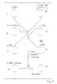
- An enzyme inhibition assay was performed using a microfluidic device having a well/channel structure as shown in Figure 3. Standard semiconductor photolithographic techniques were used to etch channels 70 ⁇ m wide and 10 ⁇ m deep, in a 525 ⁇ m thick soda lime glass substrate, and a second 2 mm thick layer of glass having 3 mm diameter holes drilled through it, was thermally bonded to the first, providing the various wells.
- the assay solutions were prepared from stock solutions of 5000 U/mg leukocyte antigen related phosphatase (LAR) (enzyme) (New England Biolabs, Beverly, MA), 10 mM dFMUP in water, a fluorogenic substrate for LAR (substrate)(available from Molecular Probes, Eugene, OR), and 1.4 mM of a known competitive inhibitor of LAR (inhibitor).
- LAR leukocyte antigen related phosphatase
- Detection of fluorescence was carried out using a Nikon inverted Microscope Diaphot 200, with a Nikon P101 photometer controller, for epifluorescent detection.
- An Opti-Quip 1200-1500 50W tungsten/halogen lamp coupled through a 10X microscope objective provided the light source.
- Excitation and emission wavelengths were selected with a DAPI filter cube (Chroma, Brattleboro VT) fitted with a DM400 dichroic mirror, 340-380 nm excitation filter and 435-485 nm barrier filter.
- Reagent well currents and voltages on the chip were controlled using a Caliper 3180 Chip Controller (Palo Alto, CA). The currents and voltages ranged +/- 10 ⁇ A and 0-2000 V. Data was collected on a Macintosh Power PC 7200/120.
- the channels of the device were filled with running buffer by placing the buffer in a buffer well and allowing capillary action to distribute the buffer throughout the channels.
- 125 nM LAR enzyme was placed in the enzyme well, 50 ⁇ M dFMUP was placed in the substrate well and 200 ⁇ M of a known competitive inhibitor of LAR was placed in the inhibitor well.
- the assay was performed using the following injection cycle, with the indicated final reagent concentrations in the injection channel: (1) buffer; (2) substrate (17 ⁇ M); (3) buffer; (4) substrate + enzyme (83 nM); (5) buffer; and (6) substrate + inhibitor (66 ⁇ M) + enzyme.
- the total flux of reagents remained constant during each step of the assay by maintaining a constant overall sum of combined currents from the wells.
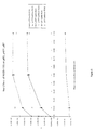
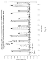
- the raw fluorescent data from this experiment are shown in Figure 4.
- the control data e.g., in the absence of NDSB-195, is shown as a gray line, running at or near the baseline of the data.
- LAR action on the dFMUP substrate produces only a moderate signal, ranging between a fluorescent intensity of 2200 and 2250. Further, while some effect of the inhibitor is apparent through this assay at later time points, that effect is relatively small.
Landscapes
- Chemical & Material Sciences (AREA)
- Health & Medical Sciences (AREA)
- Life Sciences & Earth Sciences (AREA)
- Chemical Kinetics & Catalysis (AREA)
- General Health & Medical Sciences (AREA)
- Analytical Chemistry (AREA)
- Molecular Biology (AREA)
- Dispersion Chemistry (AREA)
- General Physics & Mathematics (AREA)
- Pathology (AREA)
- Electrochemistry (AREA)
- Biochemistry (AREA)
- Engineering & Computer Science (AREA)
- Water Supply & Treatment (AREA)
- Immunology (AREA)
- Physics & Mathematics (AREA)
- Clinical Laboratory Science (AREA)
- Hematology (AREA)
- Urology & Nephrology (AREA)
- Investigating Or Analysing Biological Materials (AREA)
- Automatic Analysis And Handling Materials Therefor (AREA)
- Lubricants (AREA)
- Electrostatic Separation (AREA)
- Physical Or Chemical Processes And Apparatus (AREA)
Claims (19)
- Verfahren zur Steigerung des Materialtransports durch elektroosmotischen Fluss eines das Material enthaltenden Fluids, umfassend:die Bereitstellung von zumindest einem ersten und einem zweiten diskreten Fluidvolumen in einem fluidgefüllten Kanal, wobei ein erstes Material im ersten diskreten Fluidvolumen, jedoch nicht im zweiten Fluidvolumen enthalten ist; unddie Bereitstellung einer wirksamen Konzentration von zumindest einer zwitterionischen Verbindung im ersten diskreten Volumen des Fluids, das das erste Material enthält, um eine elektrophoretische Mobilität des ersten Materials relativ zu einem elektroosmotischen Fluss des ersten diskreten Fluidvolumens, das das Material enthält, zu reduzieren.
- Verfahren nach Anspruch 1, worin die wirksame Konzentration der zwitterionischen Verbindung im diskreten Volumen des Fluids größer ist als etwa 5 mM.
- Verfahren nach Anspruch 1, worin die wirksame Konzentration der zwitterionischen Verbindung im diskreten Volumen des Fluids von etwa 5 mM bis etwa 2 M beträgt.
- Verfahren nach Anspruch 1, worin die zwitterionischen Verbindung aus Betain, Sulfobetain, Taurin, Aminomethansulfonsäure, einer zwitterionischen Aminosäure, HEPES, CAPS, MES und Tricin ausgewählt ist.
- Verfahren nach Anspruch 4, worin die zwitterionische Verbindung ein nichtdetergierendes Sulfobetain ist.
- Verfahren nach Anspruch 5, worin das nicht-detergierende Sulfobetain aus Dimethylethylaminopropansulfonsäure, Dimethylbenzylaminopropansulfonsäure und 3-(N-Pyridinium)propansulfonsäure ausgewählt ist.
- Verfahren nach Anspruch 1, worin das Material eine Vielzahl unterschiedlich geladener chemischer Spezies umfasst.
- Verfahren nach Anspruch 1, worin das Material ein Protein umfasst.
- Verfahren nach Anspruch 8, worin das Protein ein Enzym ist.
- Verfahren nach Anspruch 1, worin die Leitung und der Transport des diskreten Volumen des Fluids in zumindest einem mikroskaligen Kanal durchgeführt wird.
- Verfahren nach Anspruch 1, worin das das Material enthaltende diskrete Volumen des Fluids in einem mikroskaligen Fluidiksystem angeordnet ist, welches Folgendes umfasst:ein Substrat mit zumindest zwei darin angeordneten sich kreuzenden Kanälen, zumindest drei Öffnungen, die im Substrat ausgebildet und in Fluidkommunikation mit freien Enden der zumindest zwei sich kreuzenden Kanäle sind; undeine separate Elektrode, die in elektrischem Kontakt mit jeder der Öffnungen angeordnet ist, wodurch ein in jeder der Öffnungen enthaltenes Fluid in elektrischem Kontakt mit den Elektroden steht.
- Verfahren nach Anspruch 1, worin das Verfahren den Transport mittels Elektroosmose von zumindest einem ersten und einem zweiten diskreten Fluidvolumen entlang dem fluidgefüllten Kanal umfasst und worin:der erste Schritt der Bereitstellung die Einführung des ersten und des zweiten Fluidvolumens in den fluidgefüllten Kanal umfasst, worin das zumindest erste diskrete Fluidvolumen das erste Material umfasst, das zumindest eine erste chemische Spezies mit einer anderen Nettoladung als eine zumindest zweite chemische Spezies, die im zweiten diskreten Fluidvolumen enthalten ist, ausbildet;der zweite Schritt der Bereitstellung die Bereitstellung einer wirksamen Konzentration einer zwitterionischen Verbindung innerhalb eines jeden der zumindest ersten und zweiten Fluidvolumen zur Reduktion der elektrophoretischen Mobilität der ersten und der zweiten geladenen chemischen Spezies relativ zu einer elektroosmotischen Mobilität des ersten bzw. des zweiten Fluidvolumens umfasst; unddas erste und das zweite diskrete Fluidvolumen durch Anlegen einer Spannung von einem Punkt im Kanal zu einem anderen Punkt im Kanal transportiert werden, wodurch das zumindest erste und zweite Fluidvolumen entlang des fluidgefüllten Kanals transportiert werden.
- Verfahren nach Anspruch 12, worin das erste und das zweite diskrete Fluidvolumen im Wesentlichen ohne Vermischen der ersten oder der zweiten chemischen Spezies entlang dem fluidgefüllten Kanal transportiert werden.
- Verfahren nach Anspruch 13, worin jedes des ersten und des zweiten diskreten Fluidvolumen zumindest zwei unterschiedlich geladene chemische Spezies umfasst.
- Verfahren nach Anspruch 14, worin die geladene chemische Spezies eine positiv geladene chemische Spezies umfasst.
- Verfahren nach Anspruch 14, worin die geladene chemische Spezies eine negativ geladene chemische Spezies umfasst.
- Mikrofluidiksystem, umfassend:zumindest drei an freien Eden von zumindest zwei sich kreuzenden Kanälen angeordnete Öffnungen, worin zumindest einer der Kanäle zumindest eine Querschnittsgröße von etwa 1 µm bis etwa 500 µm aufweist und worin zumindest einer der Kanäle zur Fortpflanzung eines freien elektroosmotischen Flusses eines Fluids im Kanal fähig ist;eine Elektrode, die in elektrischem Kontakt mit jeder der Öffnungen angeordnet ist; undzumindest ein erstes und ein zweites diskretes Fluidvolumen, die in zumindest einem der Kanäle angeordnet sind, wobei die Elektroden ein elektrisches Feld an dem ersten und dem zweiten diskreten Fluidvolumen erzeugen und worin das erste und das zweite diskrete Fluidvolumen eine wirksame Konzentration einer zwitterionischen Verbindung umfassen, um die elektrophoretische Mobilität eines im ersten diskreten Fluidvolumen enthaltenen Materials relativ zu einem elektroosmotischen Fluss des ersten diskreten Fluidvolumens zu reduzieren.
- Mikrofluidiksystem nach Anspruch 17, worin die Fluidkanäle Rillen umfassen, die in einer Oberfläche eines ersten planaren Substrats ausgebildet sind, und ein zweites planares Substrat über das erste planare Substrat gelegt ist, um die Fluidkanäle zu bilden.
- Mikrofluidiksystem nach Anspruch 18, worin zumindest eines des ersten und des zweiten planaren Substrats Siliciumoxid umfasst.
Applications Claiming Priority (3)
| Application Number | Priority Date | Filing Date | Title |
|---|---|---|---|
| US08/833,279 US5964995A (en) | 1997-04-04 | 1997-04-04 | Methods and systems for enhanced fluid transport |
| US833279 | 1997-04-04 | ||
| PCT/US1998/006256 WO1998045929A1 (en) | 1997-04-04 | 1998-03-30 | Methods and systems for enhanced fluid transport |
Publications (3)
| Publication Number | Publication Date |
|---|---|
| EP0972333A1 EP0972333A1 (de) | 2000-01-19 |
| EP0972333A4 EP0972333A4 (de) | 2000-06-28 |
| EP0972333B1 true EP0972333B1 (de) | 2004-11-24 |
Family
ID=25263963
Family Applications (1)
| Application Number | Title | Priority Date | Filing Date |
|---|---|---|---|
| EP98913300A Expired - Lifetime EP0972333B1 (de) | 1997-04-04 | 1998-03-30 | Verfahren und systeme zum verbesserten flüssigkeitstransport |
Country Status (8)
| Country | Link |
|---|---|
| US (3) | US5964995A (de) |
| EP (1) | EP0972333B1 (de) |
| AT (1) | ATE283571T1 (de) |
| AU (1) | AU739133B2 (de) |
| CA (1) | CA2284622A1 (de) |
| DE (1) | DE69827781T2 (de) |
| ES (1) | ES2234107T3 (de) |
| WO (1) | WO1998045929A1 (de) |
Families Citing this family (124)
| Publication number | Priority date | Publication date | Assignee | Title |
|---|---|---|---|---|
| US6048734A (en) | 1995-09-15 | 2000-04-11 | The Regents Of The University Of Michigan | Thermal microvalves in a fluid flow method |
| US5885470A (en) | 1997-04-14 | 1999-03-23 | Caliper Technologies Corporation | Controlled fluid transport in microfabricated polymeric substrates |
| US5942443A (en) | 1996-06-28 | 1999-08-24 | Caliper Technologies Corporation | High throughput screening assay systems in microscale fluidic devices |
| CA2258489C (en) | 1996-06-28 | 2004-01-27 | Caliper Technologies Corporation | High-throughput screening assay systems in microscale fluidic devices |
| US5964995A (en) * | 1997-04-04 | 1999-10-12 | Caliper Technologies Corp. | Methods and systems for enhanced fluid transport |
| US6235471B1 (en) | 1997-04-04 | 2001-05-22 | Caliper Technologies Corp. | Closed-loop biochemical analyzers |
| US6391622B1 (en) | 1997-04-04 | 2002-05-21 | Caliper Technologies Corp. | Closed-loop biochemical analyzers |
| JP4171075B2 (ja) * | 1997-04-25 | 2008-10-22 | カリパー・ライフ・サイエンシズ・インコーポレーテッド | 改良されたチャネル幾何学的形状を組み込む微小流体装置 |
| US7033474B1 (en) | 1997-04-25 | 2006-04-25 | Caliper Life Sciences, Inc. | Microfluidic devices incorporating improved channel geometries |
| US6613512B1 (en) | 1997-06-09 | 2003-09-02 | Caliper Technologies Corp. | Apparatus and method for correcting for variable velocity in microfluidic systems |
| US6425972B1 (en) | 1997-06-18 | 2002-07-30 | Calipher Technologies Corp. | Methods of manufacturing microfabricated substrates |
| US5989402A (en) | 1997-08-29 | 1999-11-23 | Caliper Technologies Corp. | Controller/detector interfaces for microfluidic systems |
| US6251343B1 (en) | 1998-02-24 | 2001-06-26 | Caliper Technologies Corp. | Microfluidic devices and systems incorporating cover layers |
| US7497994B2 (en) | 1998-02-24 | 2009-03-03 | Khushroo Gandhi | Microfluidic devices and systems incorporating cover layers |
| US6756019B1 (en) | 1998-02-24 | 2004-06-29 | Caliper Technologies Corp. | Microfluidic devices and systems incorporating cover layers |
| US6123798A (en) * | 1998-05-06 | 2000-09-26 | Caliper Technologies Corp. | Methods of fabricating polymeric structures incorporating microscale fluidic elements |
| US6306590B1 (en) | 1998-06-08 | 2001-10-23 | Caliper Technologies Corp. | Microfluidic matrix localization apparatus and methods |
| WO1999064836A1 (en) | 1998-06-08 | 1999-12-16 | Caliper Technologies Corp. | Microfluidic devices, systems and methods for performing integrated reactions and separations |
| US6540896B1 (en) | 1998-08-05 | 2003-04-01 | Caliper Technologies Corp. | Open-Field serial to parallel converter |
| US6447724B1 (en) | 1998-08-11 | 2002-09-10 | Caliper Technologies Corp. | DNA sequencing using multiple fluorescent labels being distinguishable by their decay times |
| US6716394B2 (en) | 1998-08-11 | 2004-04-06 | Caliper Technologies Corp. | DNA sequencing using multiple fluorescent labels being distinguishable by their decay times |
| US6149787A (en) | 1998-10-14 | 2000-11-21 | Caliper Technologies Corp. | External material accession systems and methods |
| US6416642B1 (en) | 1999-01-21 | 2002-07-09 | Caliper Technologies Corp. | Method and apparatus for continuous liquid flow in microscale channels using pressure injection, wicking, and electrokinetic injection |
| JP4515640B2 (ja) * | 1999-02-02 | 2010-08-04 | カリパー・ライフ・サイエンシズ・インク. | タンパク質特性決定方法、装置及びシステム |
| ATE556149T1 (de) | 1999-02-23 | 2012-05-15 | Caliper Life Sciences Inc | Manipulation von mikropartikeln in mikrofluidischen systemen |
| US6326083B1 (en) | 1999-03-08 | 2001-12-04 | Calipher Technologies Corp. | Surface coating for microfluidic devices that incorporate a biopolymer resistant moiety |
| US6500323B1 (en) | 1999-03-26 | 2002-12-31 | Caliper Technologies Corp. | Methods and software for designing microfluidic devices |
| US7247490B2 (en) | 1999-04-06 | 2007-07-24 | Uab Research Foundation | Method for screening crystallization conditions in solution crystal growth |
| US7250305B2 (en) * | 2001-07-30 | 2007-07-31 | Uab Research Foundation | Use of dye to distinguish salt and protein crystals under microcrystallization conditions |
| US7214540B2 (en) | 1999-04-06 | 2007-05-08 | Uab Research Foundation | Method for screening crystallization conditions in solution crystal growth |
| US6303343B1 (en) | 1999-04-06 | 2001-10-16 | Caliper Technologies Corp. | Inefficient fast PCR |
| US6306273B1 (en) | 1999-04-13 | 2001-10-23 | Aclara Biosciences, Inc. | Methods and compositions for conducting processes in microfluidic devices |
| US6322683B1 (en) * | 1999-04-14 | 2001-11-27 | Caliper Technologies Corp. | Alignment of multicomponent microfabricated structures |
| US6458259B1 (en) | 1999-05-11 | 2002-10-01 | Caliper Technologies Corp. | Prevention of surface adsorption in microchannels by application of electric current during pressure-induced flow |
| US6592821B1 (en) | 1999-05-17 | 2003-07-15 | Caliper Technologies Corp. | Focusing of microparticles in microfluidic systems |
| CA2373347A1 (en) | 1999-05-17 | 2000-11-23 | Caliper Technologies Corporation | Focusing of microparticles in microfluidic systems |
| WO2000073799A1 (en) | 1999-06-01 | 2000-12-07 | Caliper Technologies Corp. | Microscale assays and microfluidic devices for transporter, gradient induced, and binding activities |
| AU6068300A (en) | 1999-07-06 | 2001-01-22 | Caliper Technologies Corporation | Microfluidic systems and methods for determining modulator kinetics |
| US6495104B1 (en) | 1999-08-19 | 2002-12-17 | Caliper Technologies Corp. | Indicator components for microfluidic systems |
| US6858185B1 (en) | 1999-08-25 | 2005-02-22 | Caliper Life Sciences, Inc. | Dilutions in high throughput systems with a single vacuum source |
| US6613581B1 (en) | 1999-08-26 | 2003-09-02 | Caliper Technologies Corp. | Microfluidic analytic detection assays, devices, and integrated systems |
| AU7101000A (en) | 1999-09-10 | 2001-04-10 | Caliper Technologies Corporation | Microfabrication methods and devices |
| CA2385618A1 (en) * | 1999-10-08 | 2001-04-19 | Caliper Technologies Corporation | Use of nernstein voltage sensitive dyes in measuring transmembrane voltage |
| US6386014B1 (en) | 1999-11-18 | 2002-05-14 | Eagle Research Corporation | Energy measurement device for flowing gas using microminiature gas chromatograph |
| US6271038B1 (en) | 1999-12-15 | 2001-08-07 | Glaxo Wellcome Inc. | Methods for high throughout determination and ranking of formulations and solubility |
| US6468761B2 (en) | 2000-01-07 | 2002-10-22 | Caliper Technologies, Corp. | Microfluidic in-line labeling method for continuous-flow protease inhibition analysis |
| US7037416B2 (en) * | 2000-01-14 | 2006-05-02 | Caliper Life Sciences, Inc. | Method for monitoring flow rate using fluorescent markers |
| US7485454B1 (en) | 2000-03-10 | 2009-02-03 | Bioprocessors Corp. | Microreactor |
| US6749735B1 (en) | 2000-03-16 | 2004-06-15 | David Le Febre | Electromobility focusing controlled channel electrophoresis system |
| US7141152B2 (en) * | 2000-03-16 | 2006-11-28 | Le Febre David A | Analyte species separation system |
| US20020012971A1 (en) * | 2000-03-20 | 2002-01-31 | Mehta Tammy Burd | PCR compatible nucleic acid sieving medium |
| EP1285106A2 (de) * | 2000-03-31 | 2003-02-26 | Micronics, Inc. | Proteinkristallisierung in mikroflüssigkeitstrukturen |
| US6733645B1 (en) | 2000-04-18 | 2004-05-11 | Caliper Technologies Corp. | Total analyte quantitation |
| US6669831B2 (en) | 2000-05-11 | 2003-12-30 | Caliper Technologies Corp. | Microfluidic devices and methods to regulate hydrodynamic and electrical resistance utilizing bulk viscosity enhancers |
| AU6152301A (en) | 2000-05-12 | 2001-11-26 | Caliper Techn Corp | Detection of nucleic acid hybridization by fluorescence polarization |
| WO2002011887A1 (en) * | 2000-08-03 | 2002-02-14 | Caliper Technologies Corp. | Methods and devices for high throughput fluid delivery |
| US20090118139A1 (en) | 2000-11-07 | 2009-05-07 | Caliper Life Sciences, Inc. | Microfluidic method and system for enzyme inhibition activity screening |
| FR2819889B1 (fr) * | 2001-01-19 | 2003-08-01 | Sebia Sa | Procede d'electrophorese capillaire en solution libre a ph alcalin |
| US6692700B2 (en) | 2001-02-14 | 2004-02-17 | Handylab, Inc. | Heat-reduction methods and systems related to microfluidic devices |
| US7192557B2 (en) | 2001-03-28 | 2007-03-20 | Handylab, Inc. | Methods and systems for releasing intracellular material from cells within microfluidic samples of fluids |
| US7010391B2 (en) * | 2001-03-28 | 2006-03-07 | Handylab, Inc. | Methods and systems for control of microfluidic devices |
| US7323140B2 (en) | 2001-03-28 | 2008-01-29 | Handylab, Inc. | Moving microdroplets in a microfluidic device |
| US7829025B2 (en) | 2001-03-28 | 2010-11-09 | Venture Lending & Leasing Iv, Inc. | Systems and methods for thermal actuation of microfluidic devices |
| US7270786B2 (en) | 2001-03-28 | 2007-09-18 | Handylab, Inc. | Methods and systems for processing microfluidic samples of particle containing fluids |
| US8895311B1 (en) | 2001-03-28 | 2014-11-25 | Handylab, Inc. | Methods and systems for control of general purpose microfluidic devices |
| US6575188B2 (en) | 2001-07-26 | 2003-06-10 | Handylab, Inc. | Methods and systems for fluid control in microfluidic devices |
| US6852287B2 (en) | 2001-09-12 | 2005-02-08 | Handylab, Inc. | Microfluidic devices having a reduced number of input and output connections |
| US7670429B2 (en) | 2001-04-05 | 2010-03-02 | The California Institute Of Technology | High throughput screening of crystallization of materials |
| DE60221240T2 (de) * | 2001-05-02 | 2007-10-31 | Applera Corp., Foster City | Konzentration und reinigung von analyten mit elektrischen feldern |
| US7723123B1 (en) | 2001-06-05 | 2010-05-25 | Caliper Life Sciences, Inc. | Western blot by incorporating an affinity purification zone |
| US6825127B2 (en) | 2001-07-24 | 2004-11-30 | Zarlink Semiconductor Inc. | Micro-fluidic devices |
| US6890409B2 (en) * | 2001-08-24 | 2005-05-10 | Applera Corporation | Bubble-free and pressure-generating electrodes for electrophoretic and electroosmotic devices |
| US6942018B2 (en) * | 2001-09-28 | 2005-09-13 | The Board Of Trustees Of The Leland Stanford Junior University | Electroosmotic microchannel cooling system |
| US20030062833A1 (en) * | 2001-10-03 | 2003-04-03 | Wen-Yen Tai | Mini-type decorative bulb capable of emitting light through entire circumferential face |
| US7459127B2 (en) | 2002-02-26 | 2008-12-02 | Siemens Healthcare Diagnostics Inc. | Method and apparatus for precise transfer and manipulation of fluids by centrifugal and/or capillary forces |
| WO2003076052A1 (en) * | 2002-03-05 | 2003-09-18 | Caliper Life Sciences, Inc. | Mixed mode microfluidic systems |
| US7252928B1 (en) | 2002-03-12 | 2007-08-07 | Caliper Life Sciences, Inc. | Methods for prevention of surface adsorption of biological materials to capillary walls in microchannels |
| US7381317B2 (en) * | 2002-08-12 | 2008-06-03 | Beckman Coulter, Inc. | Methods and compositions for capillary electrophoresis (CE) |
| US7125711B2 (en) | 2002-12-19 | 2006-10-24 | Bayer Healthcare Llc | Method and apparatus for splitting of specimens into multiple channels of a microfluidic device |
| US7094354B2 (en) | 2002-12-19 | 2006-08-22 | Bayer Healthcare Llc | Method and apparatus for separation of particles in a microfluidic device |
| US7147955B2 (en) | 2003-01-31 | 2006-12-12 | Societe Bic | Fuel cartridge for fuel cells |
| US7147764B2 (en) * | 2003-03-28 | 2006-12-12 | Applera Corporation | Dual electrode injection of analyte into a capillary electrophoretic device |
| US7435381B2 (en) | 2003-05-29 | 2008-10-14 | Siemens Healthcare Diagnostics Inc. | Packaging of microfluidic devices |
| EP1654066B1 (de) | 2003-07-31 | 2014-11-12 | Handylab, Inc. | Verarbeitung von teilchenhaltigen proben |
| US7347617B2 (en) | 2003-08-19 | 2008-03-25 | Siemens Healthcare Diagnostics Inc. | Mixing in microfluidic devices |
| US20050133371A1 (en) * | 2003-09-30 | 2005-06-23 | West Virginia University Research Corporation | Apparatus and method for Edman degradation on a microfluidic device utilizing an electroosmotic flow pump |
| EP2345739B8 (de) | 2004-05-03 | 2016-12-07 | Handylab, Inc. | Mikrofluidische Vorrichtung zur Verarbeitung polynukleotidhaltiger Proben |
| US8852862B2 (en) | 2004-05-03 | 2014-10-07 | Handylab, Inc. | Method for processing polynucleotide-containing samples |
| US7211184B2 (en) * | 2004-08-04 | 2007-05-01 | Ast Management Inc. | Capillary electrophoresis devices |
| US20070014699A1 (en) * | 2005-06-23 | 2007-01-18 | Beckman Coulter, Inc, | Methods and apparatus for improving the sensitivity of capillary zone electrophoresis |
| US8088616B2 (en) | 2006-03-24 | 2012-01-03 | Handylab, Inc. | Heater unit for microfluidic diagnostic system |
| US10900066B2 (en) | 2006-03-24 | 2021-01-26 | Handylab, Inc. | Microfluidic system for amplifying and detecting polynucleotides in parallel |
| DK2001990T3 (en) | 2006-03-24 | 2016-10-03 | Handylab Inc | Integrated microfluidic sample processing system and method for its use |
| US11806718B2 (en) | 2006-03-24 | 2023-11-07 | Handylab, Inc. | Fluorescence detector for microfluidic diagnostic system |
| US7998708B2 (en) | 2006-03-24 | 2011-08-16 | Handylab, Inc. | Microfluidic system for amplifying and detecting polynucleotides in parallel |
| WO2008061165A2 (en) | 2006-11-14 | 2008-05-22 | Handylab, Inc. | Microfluidic cartridge and method of making same |
| WO2008060604A2 (en) | 2006-11-14 | 2008-05-22 | Handylab, Inc. | Microfluidic system for amplifying and detecting polynucleotides in parallel |
| US7799656B2 (en) | 2007-03-15 | 2010-09-21 | Dalsa Semiconductor Inc. | Microchannels for BioMEMS devices |
| US8182763B2 (en) | 2007-07-13 | 2012-05-22 | Handylab, Inc. | Rack for sample tubes and reagent holders |
| US20090136385A1 (en) | 2007-07-13 | 2009-05-28 | Handylab, Inc. | Reagent Tube |
| US8133671B2 (en) | 2007-07-13 | 2012-03-13 | Handylab, Inc. | Integrated apparatus for performing nucleic acid extraction and diagnostic testing on multiple biological samples |
| US8105783B2 (en) | 2007-07-13 | 2012-01-31 | Handylab, Inc. | Microfluidic cartridge |
| US9186677B2 (en) | 2007-07-13 | 2015-11-17 | Handylab, Inc. | Integrated apparatus for performing nucleic acid extraction and diagnostic testing on multiple biological samples |
| US8287820B2 (en) | 2007-07-13 | 2012-10-16 | Handylab, Inc. | Automated pipetting apparatus having a combined liquid pump and pipette head system |
| US9618139B2 (en) | 2007-07-13 | 2017-04-11 | Handylab, Inc. | Integrated heater and magnetic separator |
| USD621060S1 (en) | 2008-07-14 | 2010-08-03 | Handylab, Inc. | Microfluidic cartridge |
| US8324372B2 (en) | 2007-07-13 | 2012-12-04 | Handylab, Inc. | Polynucleotide capture materials, and methods of using same |
| US8016260B2 (en) | 2007-07-19 | 2011-09-13 | Formulatrix, Inc. | Metering assembly and method of dispensing fluid |
| USD618820S1 (en) | 2008-07-11 | 2010-06-29 | Handylab, Inc. | Reagent holder |
| USD787087S1 (en) | 2008-07-14 | 2017-05-16 | Handylab, Inc. | Housing |
| US7927904B2 (en) | 2009-01-05 | 2011-04-19 | Dalsa Semiconductor Inc. | Method of making BIOMEMS devices |
| US8100293B2 (en) | 2009-01-23 | 2012-01-24 | Formulatrix, Inc. | Microfluidic dispensing assembly |
| EP2697657B8 (de) | 2011-04-15 | 2017-08-16 | Becton, Dickinson and Company | Mikrofluidischer abtastender echtzeit-thermocycler und verfahren zur optischen detektion mittels synchronisierter thermozyklierung und abtastung |
| USD692162S1 (en) | 2011-09-30 | 2013-10-22 | Becton, Dickinson And Company | Single piece reagent holder |
| DK3273253T3 (da) | 2011-09-30 | 2020-10-12 | Becton Dickinson Co | Forenet reagensstrimmel |
| EP2773892B1 (de) | 2011-11-04 | 2020-10-07 | Handylab, Inc. | Vorrichtung zur vorbereitung von polynukleotidproben |
| DK2810080T3 (da) | 2012-02-03 | 2024-06-17 | Becton Dickinson Co | Eksterne filer til fordeling af molekylære diagnostiske tests og bestemmelse af kompatabilitet imellem tests |
| US10022728B2 (en) | 2013-02-01 | 2018-07-17 | Arizona Board Of Regents On Behalf Of Arizona State University | Punctuated microgradients for improved separations of molecules and particles |
| WO2021102134A1 (en) | 2019-11-20 | 2021-05-27 | E Ink Corporation | Spatially variable hydrophobic layers for digital microfluidics |
| WO2021146573A1 (en) | 2020-01-17 | 2021-07-22 | E Ink Corporation | Spatially variable dielectric layers for digital microfluidics |
| US11946901B2 (en) | 2020-01-27 | 2024-04-02 | Nuclera Ltd | Method for degassing liquid droplets by electrical actuation at higher temperatures |
| KR20220141862A (ko) | 2020-02-18 | 2022-10-20 | 뉴클라 뉴클레익스 리미티드 | 전기습윤 장치 구동을 위한 적응형 게이트 구동 |
| JP2023514278A (ja) | 2020-02-19 | 2023-04-05 | ヌークレラ ヌクリークス, リミテッド | EWoDアレイの高周波数AC駆動のためのラッチ付きトランジスタ駆動 |
| WO2021222061A1 (en) | 2020-04-27 | 2021-11-04 | Nuclera Nucleics Ltd. | Segmented top plate for variable driving and short protection for digital microfluidics |
Family Cites Families (19)
| Publication number | Priority date | Publication date | Assignee | Title |
|---|---|---|---|---|
| US4675300A (en) * | 1985-09-18 | 1987-06-23 | The Board Of Trustees Of The Leland Stanford Junior University | Laser-excitation fluorescence detection electrokinetic separation |
| US4908112A (en) * | 1988-06-16 | 1990-03-13 | E. I. Du Pont De Nemours & Co. | Silicon semiconductor wafer for analyzing micronic biological samples |
| US5096554A (en) * | 1989-08-07 | 1992-03-17 | Applied Biosystems, Inc. | Nucleic acid fractionation by counter-migration capillary electrophoresis |
| US5264101A (en) * | 1989-11-06 | 1993-11-23 | Applied Biosystems, Inc. | Capillary electrophoresis molecular weight separation of biomolecules using a polymer-containing solution |
| US5181999A (en) * | 1989-11-06 | 1993-01-26 | Applied Biosystems, Inc. | Capillary electrophoresis method with polymer tube coating |
| US5192405A (en) * | 1991-01-11 | 1993-03-09 | Millipore Corporation | Process for effecting high efficiency separations by capillary electrophoresis |
| US5415747A (en) * | 1993-08-16 | 1995-05-16 | Hewlett-Packard Company | Capillary electrophoresis using zwitterion-coated capillary tubes |
| US5391274A (en) * | 1993-10-18 | 1995-02-21 | Beckman Instruments, Inc. | Methods for controlling electroosmotic flow in coated capillary electrophoresis columns |
| US6001229A (en) * | 1994-08-01 | 1999-12-14 | Lockheed Martin Energy Systems, Inc. | Apparatus and method for performing microfluidic manipulations for chemical analysis |
| US5585069A (en) * | 1994-11-10 | 1996-12-17 | David Sarnoff Research Center, Inc. | Partitioned microelectronic and fluidic device array for clinical diagnostics and chemical synthesis |
| US5632876A (en) * | 1995-06-06 | 1997-05-27 | David Sarnoff Research Center, Inc. | Apparatus and methods for controlling fluid flow in microchannels |
| US5630924A (en) * | 1995-04-20 | 1997-05-20 | Perseptive Biosystems, Inc. | Compositions, methods and apparatus for ultrafast electroseparation analysis |
| US5856174A (en) * | 1995-06-29 | 1999-01-05 | Affymetrix, Inc. | Integrated nucleic acid diagnostic device |
| US5578179A (en) * | 1995-07-12 | 1996-11-26 | The Perkin-Elmer Corporation | Method and silicate composition for conditioning silica surfaces |
| US5660701A (en) * | 1996-02-29 | 1997-08-26 | Bio-Rad Laboratories, Inc. | Protein separations by capillary electrophoresis using amino acid-containing buffers |
| US5779868A (en) * | 1996-06-28 | 1998-07-14 | Caliper Technologies Corporation | Electropipettor and compensation means for electrophoretic bias |
| US5800690A (en) * | 1996-07-03 | 1998-09-01 | Caliper Technologies Corporation | Variable control of electroosmotic and/or electrophoretic forces within a fluid-containing structure via electrical forces |
| BR9712800A (pt) * | 1996-09-06 | 1999-11-23 | Nanogen Inc | Processos e materias para otimização de reações de hibridização eletrônica |
| US5964995A (en) * | 1997-04-04 | 1999-10-12 | Caliper Technologies Corp. | Methods and systems for enhanced fluid transport |
-
1997
- 1997-04-04 US US08/833,279 patent/US5964995A/en not_active Expired - Lifetime
-
1998
- 1998-03-30 AT AT98913300T patent/ATE283571T1/de not_active IP Right Cessation
- 1998-03-30 ES ES98913300T patent/ES2234107T3/es not_active Expired - Lifetime
- 1998-03-30 AU AU67887/98A patent/AU739133B2/en not_active Ceased
- 1998-03-30 CA CA002284622A patent/CA2284622A1/en not_active Abandoned
- 1998-03-30 DE DE69827781T patent/DE69827781T2/de not_active Expired - Lifetime
- 1998-03-30 WO PCT/US1998/006256 patent/WO1998045929A1/en not_active Ceased
- 1998-03-30 EP EP98913300A patent/EP0972333B1/de not_active Expired - Lifetime
-
1999
- 1999-05-11 US US09/309,365 patent/US6129826A/en not_active Expired - Lifetime
-
2000
- 2000-07-11 US US09/613,962 patent/US6471841B1/en not_active Expired - Lifetime
Also Published As
| Publication number | Publication date |
|---|---|
| EP0972333A4 (de) | 2000-06-28 |
| US5964995A (en) | 1999-10-12 |
| ATE283571T1 (de) | 2004-12-15 |
| US6129826A (en) | 2000-10-10 |
| DE69827781D1 (de) | 2004-12-30 |
| CA2284622A1 (en) | 1998-10-15 |
| AU6788798A (en) | 1998-10-30 |
| ES2234107T3 (es) | 2005-06-16 |
| EP0972333A1 (de) | 2000-01-19 |
| AU739133B2 (en) | 2001-10-04 |
| US6471841B1 (en) | 2002-10-29 |
| WO1998045929A1 (en) | 1998-10-15 |
| DE69827781T2 (de) | 2006-01-12 |
Similar Documents
| Publication | Publication Date | Title |
|---|---|---|
| US6471841B1 (en) | Methods and systems for enhanced fluid transport | |
| WO1998045929A9 (en) | Methods and systems for enhanced fluid transport | |
| AU730827B2 (en) | Apparatus and methods for correcting for variable velocity in microfluidic systems | |
| US7041509B2 (en) | High throughput screening assay systems in microscale fluidic devices | |
| KR100351531B1 (ko) | 기하형상이 개선된 채널을 채용하는 미소 유체 장치 | |
| US6274089B1 (en) | Microfluidic devices, systems and methods for performing integrated reactions and separations | |
| US7160423B2 (en) | Mixed mode microfluidic systems | |
| US6551836B1 (en) | Microfluidic devices, systems and methods for performing integrated reactions and separations | |
| US7033474B1 (en) | Microfluidic devices incorporating improved channel geometries | |
| WO1998000231A9 (en) | High-throughput screening assay systems in microscale fluidic devices | |
| EP1007953A1 (de) | Integrierte mikrofluidische vorrichtungen | |
| AU747713B2 (en) | Apparatus and methods for correcting for variable velocity in microfluidic systems | |
| AU2005234635B2 (en) | High-throughput screening assay systems in microscale fluidic devices | |
| CA2443272A1 (en) | Electropipettor and compensation means for electrophoretic bias |
Legal Events
| Date | Code | Title | Description |
|---|---|---|---|
| PUAI | Public reference made under article 153(3) epc to a published international application that has entered the european phase |
Free format text: ORIGINAL CODE: 0009012 |
|
| 17P | Request for examination filed |
Effective date: 19991014 |
|
| AK | Designated contracting states |
Kind code of ref document: A1 Designated state(s): AT BE CH DE DK ES FI FR GB GR IE IT LI LU MC NL PT SE |
|
| RIN1 | Information on inventor provided before grant (corrected) |
Inventor name: JEONG, SANG Inventor name: NIKIFOROV, THEO, T. |
|
| A4 | Supplementary search report drawn up and despatched |
Effective date: 20000516 |
|
| AK | Designated contracting states |
Kind code of ref document: A4 Designated state(s): AT BE CH DE DK ES FI FR GB GR IE IT LI LU MC NL PT SE |
|
| RAP1 | Party data changed (applicant data changed or rights of an application transferred) |
Owner name: CALIPER TECHNOLOGIES, CORP. |
|
| 17Q | First examination report despatched |
Effective date: 20020425 |
|
| RAP1 | Party data changed (applicant data changed or rights of an application transferred) |
Owner name: CALIPER LIFE SCIENCE, INC. |
|
| RAP1 | Party data changed (applicant data changed or rights of an application transferred) |
Owner name: CALIPER LIFE SCIENCES, INC. |
|
| GRAP | Despatch of communication of intention to grant a patent |
Free format text: ORIGINAL CODE: EPIDOSNIGR1 |
|
| RAP1 | Party data changed (applicant data changed or rights of an application transferred) |
Owner name: CALIPER LIFE SCIENCES, INC. |
|
| GRAS | Grant fee paid |
Free format text: ORIGINAL CODE: EPIDOSNIGR3 |
|
| GRAA | (expected) grant |
Free format text: ORIGINAL CODE: 0009210 |
|
| AK | Designated contracting states |
Kind code of ref document: B1 Designated state(s): AT BE CH DE DK ES FI FR GB GR IE IT LI LU MC NL PT SE |
|
| PG25 | Lapsed in a contracting state [announced via postgrant information from national office to epo] |
Ref country code: FI Free format text: LAPSE BECAUSE OF FAILURE TO SUBMIT A TRANSLATION OF THE DESCRIPTION OR TO PAY THE FEE WITHIN THE PRESCRIBED TIME-LIMIT Effective date: 20041124 Ref country code: BE Free format text: LAPSE BECAUSE OF FAILURE TO SUBMIT A TRANSLATION OF THE DESCRIPTION OR TO PAY THE FEE WITHIN THE PRESCRIBED TIME-LIMIT Effective date: 20041124 Ref country code: AT Free format text: LAPSE BECAUSE OF FAILURE TO SUBMIT A TRANSLATION OF THE DESCRIPTION OR TO PAY THE FEE WITHIN THE PRESCRIBED TIME-LIMIT Effective date: 20041124 |
|
| REG | Reference to a national code |
Ref country code: GB Ref legal event code: FG4D |
|
| REG | Reference to a national code |
Ref country code: CH Ref legal event code: EP |
|
| REF | Corresponds to: |
Ref document number: 69827781 Country of ref document: DE Date of ref document: 20041230 Kind code of ref document: P |
|
| REG | Reference to a national code |
Ref country code: IE Ref legal event code: FG4D |
|
| PG25 | Lapsed in a contracting state [announced via postgrant information from national office to epo] |
Ref country code: SE Free format text: LAPSE BECAUSE OF FAILURE TO SUBMIT A TRANSLATION OF THE DESCRIPTION OR TO PAY THE FEE WITHIN THE PRESCRIBED TIME-LIMIT Effective date: 20050224 Ref country code: GR Free format text: LAPSE BECAUSE OF FAILURE TO SUBMIT A TRANSLATION OF THE DESCRIPTION OR TO PAY THE FEE WITHIN THE PRESCRIBED TIME-LIMIT Effective date: 20050224 Ref country code: DK Free format text: LAPSE BECAUSE OF FAILURE TO SUBMIT A TRANSLATION OF THE DESCRIPTION OR TO PAY THE FEE WITHIN THE PRESCRIBED TIME-LIMIT Effective date: 20050224 |
|
| PG25 | Lapsed in a contracting state [announced via postgrant information from national office to epo] |
Ref country code: LU Free format text: LAPSE BECAUSE OF NON-PAYMENT OF DUE FEES Effective date: 20050330 Ref country code: IE Free format text: LAPSE BECAUSE OF NON-PAYMENT OF DUE FEES Effective date: 20050330 |
|
| PG25 | Lapsed in a contracting state [announced via postgrant information from national office to epo] |
Ref country code: MC Free format text: LAPSE BECAUSE OF NON-PAYMENT OF DUE FEES Effective date: 20050331 Ref country code: LI Free format text: LAPSE BECAUSE OF NON-PAYMENT OF DUE FEES Effective date: 20050331 Ref country code: ES Free format text: LAPSE BECAUSE OF NON-PAYMENT OF DUE FEES Effective date: 20050331 Ref country code: CH Free format text: LAPSE BECAUSE OF NON-PAYMENT OF DUE FEES Effective date: 20050331 |
|
| REG | Reference to a national code |
Ref country code: ES Ref legal event code: FG2A Ref document number: 2234107 Country of ref document: ES Kind code of ref document: T3 |
|
| ET | Fr: translation filed | ||
| PLBE | No opposition filed within time limit |
Free format text: ORIGINAL CODE: 0009261 |
|
| STAA | Information on the status of an ep patent application or granted ep patent |
Free format text: STATUS: NO OPPOSITION FILED WITHIN TIME LIMIT |
|
| PG25 | Lapsed in a contracting state [announced via postgrant information from national office to epo] |
Ref country code: NL Free format text: LAPSE BECAUSE OF NON-PAYMENT OF DUE FEES Effective date: 20051001 |
|
| REG | Reference to a national code |
Ref country code: CH Ref legal event code: PL |
|
| 26N | No opposition filed |
Effective date: 20050825 |
|
| NLV4 | Nl: lapsed or anulled due to non-payment of the annual fee |
Effective date: 20051001 |
|
| REG | Reference to a national code |
Ref country code: IE Ref legal event code: MM4A |
|
| PGFP | Annual fee paid to national office [announced via postgrant information from national office to epo] |
Ref country code: IT Payment date: 20060331 Year of fee payment: 9 |
|
| REG | Reference to a national code |
Ref country code: ES Ref legal event code: FD2A Effective date: 20050331 |
|
| PG25 | Lapsed in a contracting state [announced via postgrant information from national office to epo] |
Ref country code: PT Free format text: LAPSE BECAUSE OF NON-PAYMENT OF DUE FEES Effective date: 20050424 |
|
| PGFP | Annual fee paid to national office [announced via postgrant information from national office to epo] |
Ref country code: GB Payment date: 20080327 Year of fee payment: 11 |
|
| PG25 | Lapsed in a contracting state [announced via postgrant information from national office to epo] |
Ref country code: IT Free format text: LAPSE BECAUSE OF NON-PAYMENT OF DUE FEES Effective date: 20070330 |
|
| GBPC | Gb: european patent ceased through non-payment of renewal fee |
Effective date: 20090330 |
|
| PG25 | Lapsed in a contracting state [announced via postgrant information from national office to epo] |
Ref country code: GB Free format text: LAPSE BECAUSE OF NON-PAYMENT OF DUE FEES Effective date: 20090330 |
|
| REG | Reference to a national code |
Ref country code: FR Ref legal event code: PLFP Year of fee payment: 19 |
|
| REG | Reference to a national code |
Ref country code: FR Ref legal event code: PLFP Year of fee payment: 20 |
|
| PGFP | Annual fee paid to national office [announced via postgrant information from national office to epo] |
Ref country code: FR Payment date: 20170327 Year of fee payment: 20 |
|
| PGFP | Annual fee paid to national office [announced via postgrant information from national office to epo] |
Ref country code: DE Payment date: 20170329 Year of fee payment: 20 |
|
| REG | Reference to a national code |
Ref country code: DE Ref legal event code: R071 Ref document number: 69827781 Country of ref document: DE |