EP0972455B1 - Verfahren und Vorrichtung zur Kühlung einer wässerigen Flüssigkeit - Google Patents
Verfahren und Vorrichtung zur Kühlung einer wässerigen Flüssigkeit Download PDFInfo
- Publication number
- EP0972455B1 EP0972455B1 EP99202292A EP99202292A EP0972455B1 EP 0972455 B1 EP0972455 B1 EP 0972455B1 EP 99202292 A EP99202292 A EP 99202292A EP 99202292 A EP99202292 A EP 99202292A EP 0972455 B1 EP0972455 B1 EP 0972455B1
- Authority
- EP
- European Patent Office
- Prior art keywords
- vessel
- aqueous liquid
- heat exchanger
- liquid
- vapour
- Prior art date
- Legal status (The legal status is an assumption and is not a legal conclusion. Google has not performed a legal analysis and makes no representation as to the accuracy of the status listed.)
- Expired - Lifetime
Links
Images



Classifications
-
- F—MECHANICAL ENGINEERING; LIGHTING; HEATING; WEAPONS; BLASTING
- F25—REFRIGERATION OR COOLING; COMBINED HEATING AND REFRIGERATION SYSTEMS; HEAT PUMP SYSTEMS; MANUFACTURE OR STORAGE OF ICE; LIQUEFACTION SOLIDIFICATION OF GASES
- F25D—REFRIGERATORS; COLD ROOMS; ICE-BOXES; COOLING OR FREEZING APPARATUS NOT OTHERWISE PROVIDED FOR
- F25D31/00—Other cooling or freezing apparatus
-
- A—HUMAN NECESSITIES
- A23—FOODS OR FOODSTUFFS; TREATMENT THEREOF, NOT COVERED BY OTHER CLASSES
- A23B—PRESERVATION OF FOODS, FOODSTUFFS OR NON-ALCOHOLIC BEVERAGES; CHEMICAL RIPENING OF FRUIT OR VEGETABLES
- A23B2/00—Preservation of foods or foodstuffs, in general
- A23B2/80—Freezing; Subsequent thawing; Cooling
-
- A—HUMAN NECESSITIES
- A23—FOODS OR FOODSTUFFS; TREATMENT THEREOF, NOT COVERED BY OTHER CLASSES
- A23L—FOODS, FOODSTUFFS OR NON-ALCOHOLIC BEVERAGES, NOT OTHERWISE PROVIDED FOR; PREPARATION OR TREATMENT THEREOF
- A23L23/00—Soups; Sauces; Preparation or treatment thereof
-
- F—MECHANICAL ENGINEERING; LIGHTING; HEATING; WEAPONS; BLASTING
- F25—REFRIGERATION OR COOLING; COMBINED HEATING AND REFRIGERATION SYSTEMS; HEAT PUMP SYSTEMS; MANUFACTURE OR STORAGE OF ICE; LIQUEFACTION SOLIDIFICATION OF GASES
- F25D—REFRIGERATORS; COLD ROOMS; ICE-BOXES; COOLING OR FREEZING APPARATUS NOT OTHERWISE PROVIDED FOR
- F25D3/00—Devices using other cold materials; Devices using cold-storage bodies
- F25D3/10—Devices using other cold materials; Devices using cold-storage bodies using liquefied gases, e.g. liquid air
Definitions
- This invention relates to a method and apparatus for cooling an aqueous liquid and, more particularly but not exclusively, is concerned with a method and apparatus for cooling sauces.
- the present invention provides a simple, relatively inexpensive alternative ideally suited for the smaller factory.
- a method of cooling an aqueous liquid which method comprises the steps of:
- said method includes the step of returning condensate from step (c) to said aqueous liquid in said vessel.
- the condensate could however be recovered separately for subsequent use, for example for blending into aqueous liquid in a different vessel.
- said aqueous liquid is an edible sauce.
- the present invention also provides an apparatus for carrying out a method according to the invention, which apparatus comprises:-
- said pressure reducing means comprises a vacuum pump.
- said pressure reducing means comprises an eductor.
- said pressure reducing means comprise a plurality of eductors connected in cascade.
- said apparatus includes a first temperature sensor adapted to generate a signal indicative of the temperature of aqueous liquid in said vessel, a second temperature sensor adapted to generate a signal indicative of the temperature of gaseous cryogen leaving said heat exchanger, a control valve adapted to control the flow of cryogenic liquid to said heat exchanger, and control means responsive to the difference between the signals from said first and second temperature sensors to open and close said control valve so that the temperature difference between the aqueous liquid in said vessel and the cryogenic vapour leaving said heat exchanger is substantially constant.
- said heat exchanger is disposed inside said vessel.
- this is not essential.
- said heat exchanger is disposed above said vessel and a pipe is provided so that, in use, condensate formed in said heat exchanger can flow back into said vessel.
- a sauce is prepared and introduced into a vessel 1 at about 90°C.
- the vessel 1 is covered with a lid 2 and a vacuum is applied via vacuum pump 3.
- the sauce begins to boil and part of the liquid turns to vapour.
- the energy required for vaporization comes from the sauce which becomes progressively colder as the pressure drops.
- vapour itself leaves the vessel 1 through pipe 4. Because of its high water content (not to mention innumerable other organics) it is highly undesirable that this vapour should be introduced into the vacuum pump 3. As such it is usually passed through a heat exchanger where it is indirectly cooled by cold refrigerant (typically brine) from a mechanical refrigeration system. Any condensate is recovered in phase separator 6 whilst the residual gas passes through pipe 7 to the vacuum pump 3.
- cold refrigerant typically brine
- the apparatus comprises a vessel 11 having a lid 12.
- sauce at 90°C is introduced into the vessel 11 and the lid is secured thereto.
- a vacuum is then applied via a pipe 14 by passing steam through an eductor 13.
- the eductor 13 takes the place of the pump 3 in the embodiment shown in Fig. 1.
- the advantage of the apparatus is that the eductor has a significantly greater output at low vacuum and can thus rapidly initially depressurise the vessel 1.
- the mechanical refrigeration system for condensing the volatiles can be dispensed with.
- the disadvantages are the cost of providing and running a steam generating plant and condensing and cooling the vapour leaving the eductor 13. Furthermore, any organics in the vapour from the sauce are lost in the steam.
- FIG. 3 there is shown an apparatus which is generally identified by the reference numeral 100.
- the apparatus 100 comprises a vessel 101 provided with a lid 102.
- a pipe 104 extends from the lid 102 to an eductor 113.
- a pipe 109 is arranged to deliver liquid nitrogen to a heat exchanger 114 disposed in the lid 102.
- a pipe 115 is arranged to carry gaseous nitrogen from the heat exchanger 114 to the eductor 113.
- a sauce at 90°C is introduced into the vessel 101 which is then closed with the lid 102.
- Liquid nitrogen is then introduced into the heat exchanger 114 where it evaporates.
- the gaseous nitrogen produced passes through pipe 115 and eductor 113 where it starts reducing the pressure in the vessel 101.
- the sauce starts boiling and vapour is formed.
- the vapour rises it encounters the heat exchanger 114 which condenses the volatiles, i.e. the water vapour and organics.
- a paddle 116 is preferably provided to continuously stir the sauce.
- a vacuum pump similar to vacuum pump 3 could also be connected to the vessel 101.
- the purpose of such a vacuum pump would be to take over from the eductor 113 once it had reduced the pressure in vessel 101 as far as possible.
- eductors 113 can only provide a limited vacuum and it may be desirable once this pressure has been reached to isolate the eductor 113 and further reduce the pressure in the vessel 101 with the vacuum pump. If confined to such duty it is anticipated that the mechanical refrigeration unit and phase separator could be dispensed with.
- the volume of liquid nitrogen used for condensation provides a more than adequate flow of gaseous nitrogen for driving the eductor.
- Eductors tend to be designed either to have a high throughput with a modest reduction in pressure or a lower throughput with a higher reduction of pressure. For this reason it is anticipated that rather than a single eduction a commercial installation would use two or more eductors with different properties arranged in cascade to achieve a high eventual vacuum.
- FIG. 4 Such an apparatus is shown in Fig. 4 where parts having a similar function to parts in Fig. 3 have been given the same reference number in the "200" series.
- eductor 113 has been replaced by three eductors 213, 213' and 213" arranged in cascade and vacuum pump 203 has been provided.
- Non return valves 217 and 218 have been provided where indicated. These may be conveniently formed by electrically controlled solenoid valves.
- Eductor 213 is a high pumping capacity coarse vacuum ejector whose main function is to rapidly remove air from the headspace in the vessel 201 and maintain vapour pressure in the early part of the cooling cycle as air degasses from the sauce.
- Eductors 213' and 213'' are low capacity, high vacuum ejectors capable of removing air and/or non condensables at pressure as low as 8mbar, (which corresponds to a sauce temperature of about 4°C).
- the vacuum pump 203 is a prudent safety measure and adds additional pumping capacity and the ability to provide a lower pressure than the eductors should this be required.
- the eductors 213, 213' and 213'' are used to progressively reduce the pressure in vessel 201 to about 8mbar. If the rate of pressure reduction is not acceptable vacuum pump 203 is activated to assist in reducing the pressure to about 8mbar at which pressure a typical sauce will boil at 4°C.
- the eductors 213, 213' and 213" are preferably activated so that initially only eductor 213 is active. Later, when the vapour pressure reaches about 450mbar eductor 213' is activated in parallel with eductor 213. When the pressure reaches about 300mbar the supply of nitrogen to eductor 213 is closed off using a control valve (not shown).
- FIG. 7 A typical curve showing the boiling point of a sauce against pressure is shown in Fig. 7.
- the sauce After the sauce has been cooled it is removed from the vessel 201 which is sterilized in preparation for the next batch of sauce.
- the vessel 201 could be provided with a permanent outlet pipe in the bottom thereof and the lid 202 provided with a permanent inlet pipe.
- the use of the paddle 216 appears to have significant beneficial effect and it is postulated that this inter alia helped release bubbles of air entrapped in the sauce during its preparation.
- Design considerations for the heat exchanger 214 include ensuring that ice does not form on the surface of the heat exchanger 214. It may also be desirable to control the flow of liquid nitrogen to the heat exchanger 214 in such a way that there is a constant temperature differential between the vapour leaving the heat exchanger 214 and the sauce. For economic operation this could be set as low as 5°C although 10°C is recommended.
- Such a control system could be effected by a temperature sensor 225 in the sauce, a temperature sensor 226 in the vapour stream leaving the heat exchanger 214, and a control unit 227 arranged to open and close a control valve 228 to control the flow of liquid nitrogen through the heat exchanger 214. The control valve 228 vents to atmosphere as shown.
- sauces are made commercially in 500kg batches and the UK code of good practice requires them to be cooled to between 5° and 8°C within 90 minutes.
- liquid nitrogen is preferred, other liquid cryogens could also be used, for example liquid air, a nitrogen rich mixture of liquid oxygen and liquid nitrogen, liquid argon or liquid helium. However, liquid nitrogen is much preferred.
- the heat exchanger 214 Whilst it is preferred to locate the heat exchanger 214 in the vessel 201 it could be located in a separate vessel above the vessel 201 and arranged to return condensate directly to the vessel 201 in a similar manner to a condenser on a distillation column. Such a heat exchanger could, if desired, be provided with packing or plates in a similar manner to a distillation column. However, cleaning considerations probably make such an embodiment impractical.
- Fig. 5 shows an apparatus which is generally similar to that shown in Fig. 1 except that the heat exchanger 305 is cooled with liquid nitrogen and the vapourized nitrogen leaving the heat exchanger 305 is used to drive the vacuum pump 303.
- the remaining parts of the apparatus correspond to parts used in the embodiment of Fig. 1 and parts having similar functions have been identified by similar reference numerals but in the "300" series.
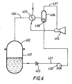
- Fig. 6 shows a variation of the apparatus shown in Fig. 5.
- the heat exchanger 405 is cooled by liquid nitrogen.
- the gaseous nitrogen leaving the heat exchanger is directed into an eductor 413.
- a small pump 420 is provided to return condensate from the phase separator 406 to the vessel 401 via pipe 421 and non-return valve 422.
Landscapes
- Engineering & Computer Science (AREA)
- Life Sciences & Earth Sciences (AREA)
- Chemical & Material Sciences (AREA)
- Food Science & Technology (AREA)
- Polymers & Plastics (AREA)
- Nutrition Science (AREA)
- Thermal Sciences (AREA)
- Health & Medical Sciences (AREA)
- Wood Science & Technology (AREA)
- Combustion & Propulsion (AREA)
- Physics & Mathematics (AREA)
- Mechanical Engineering (AREA)
- Zoology (AREA)
- General Engineering & Computer Science (AREA)
- Thermotherapy And Cooling Therapy Devices (AREA)
- Physical Or Chemical Processes And Apparatus (AREA)
- Heat Treatment Of Strip Materials And Filament Materials (AREA)
- Devices That Are Associated With Refrigeration Equipment (AREA)
- Seeds, Soups, And Other Foods (AREA)
Claims (10)
- Verfahren zum Kühlen einer wäßrigen Flüssigkeit, wobei das Verfahren die Schritte umfaßt:a) Einbringen der wäßrigen Flüssigkeit in ein Gefäß (101, 201, 301, 401);b) Vermindern des Drucks in dem Gefäß, so daß es zum Sieden der wäßrigen Flüssigkeit kommt; undc) Kondensieren von zumindest einem Teil der Flüssigkeit in dem Dampf, der beim Sieden der wäßrigen Flüssigkeit erzeugt worden ist;
dadurch gekennzeichnet daß:d) das Kondensieren durch Wärmeaustausch mit einem flüssigen Tiefkühlmittel durchgeführt wird, unde) für die Durchführung oder Unterstützung im Schritt (b) Dampf von diesem flüssigen Tiefkühlmittel verwendet wird. - Verfahren nach Anspruch 1, das einen Schritt einschließt, bei dem das Kondensat vom Schritt (c) zur wäßrigen Flüssigkeit im Gefäß (401) zurückgeführt wird.
- Verfahren nach Anspruch 1 oder 2, wobei die wäßrige Flüssigkeit eine Speisensoße ist.
- Vorrichtung zur Durchführung eines Verfahrens nach Anspruch 1, wobei die Vorrichtung umfaßt:dadurch gekennzeichnet, daß die Vorrichtung ferner umfaßt:a) ein Gefäß (101, 201, 301, 401), für die Aufnahme der wäßrigen Flüssigkeit,b) eine Einrichtung (113, 213, 213', 213", 313, 413) zur Druckverminderung, um den Druck in dem Gefäß zu vermindern, undc) einen Wärmeaustauscher (114, 214, 305, 405), um bei Verwendung ein Kühlmittel in indirekten Wärmeaustausch mit dem Dampf zu bringen, der beim Sieden der wäßrigen Flüssigkeit im Gefäß erzeugt worden ist, damit zumindest ein Teil davon kondensiert,eine Einrichtung zum Einführen eines flüssigen Tiefkühlmittels in den Wärmeaustauscher undeine Einrichtung, die es bei Verwendung ermöglicht, daß der Dampf von dem flüssigen Tiefkühlmittel den Betrieb der Einrichtung zur Druckverminderung besorgt oder unterstützt.
- Vorrichtung nach Anspruch 4, wobei die Einrichtung zur Druckverminderung eine Vakuumpumpe (203, 303) umfaßt.
- Vorrichtung nach Anspruch 4 oder 5, wobei die Einrichtung zur Druckverminderung einen Ejektor (113, 213, 213', 213", 413) umfaßt.
- Vorrichtung nach Anspruch 6, wobei die Einrichtung zur Druckverminderung eine Mehrzahl von Ejektoren (213, 213', 213") umfaßt, die in Kaskaden verbunden sind.
- Vorrichtung nach einem der Ansprüche 4 bis 7, die einen ersten Temperatursensor (225), der für die Erzeugung eines Signals geeignet ist, das die Temperatur der wäßrigen Flüssigkeit in dem Gefäß (201) anzeigt, einen zweiten Temperatursensor (226), der für die Erzeugung eines Signals geeignet ist, das die Temperatur des gasförmigen Tiefkühlmittels anzeigt, das den Wärmeaustauscher (214) verläßt, ein Regelventil (228), das geeignet ist, den Strom der Tieftemperaturflüssigkeit zum Wärmeaustauscher (214) zu steuern, und eine Regeleinrichtung (227) umfaßt, die auf den Unterschied zwischen den Signalen vom ersten und vom zweiten Temperatursensor anspricht, um das Regelventil (227) zu öffnen und zu schließen, so daß der Temperaturunterschied zwischen der wäßrigen Flüssigkeit in dem Gefäß und dem den Wärmeaustauscher verlassenden Tieftemperaturdampf im wesentlichen konstant ist.
- Vorrichtung nach einem der Ansprüche 4 bis 8, wobei sich der Wärmeaustauscher (114, 214) im Inneren des Gefäßes befindet.
- Vorrichtung nach einem der Ansprüche 4 bis 8, wobei sich der Wärmeaustauscher über dem Gefäß befindet und ein Rohr vorgesehen ist, so daß das im Wärmeaustauscher erzeugte Kondensat bei Verwendung in das Gefäß zurückfließen kann.
Priority Applications (1)
| Application Number | Priority Date | Filing Date | Title |
|---|---|---|---|
| DK99202292T DK0972455T3 (da) | 1998-07-13 | 1999-07-13 | Fremgangsmåde og apparat til afköling af en vandbaseret væske |
Applications Claiming Priority (2)
| Application Number | Priority Date | Filing Date | Title |
|---|---|---|---|
| GB9814970 | 1998-07-13 | ||
| GB9814970A GB2339467A (en) | 1998-07-13 | 1998-07-13 | Cooling an aqueous liquid |
Publications (3)
| Publication Number | Publication Date |
|---|---|
| EP0972455A2 EP0972455A2 (de) | 2000-01-19 |
| EP0972455A3 EP0972455A3 (de) | 2001-02-14 |
| EP0972455B1 true EP0972455B1 (de) | 2005-06-08 |
Family
ID=10835283
Family Applications (1)
| Application Number | Title | Priority Date | Filing Date |
|---|---|---|---|
| EP99202292A Expired - Lifetime EP0972455B1 (de) | 1998-07-13 | 1999-07-13 | Verfahren und Vorrichtung zur Kühlung einer wässerigen Flüssigkeit |
Country Status (8)
| Country | Link |
|---|---|
| US (1) | US6145321A (de) |
| EP (1) | EP0972455B1 (de) |
| AT (1) | ATE297134T1 (de) |
| DE (1) | DE69925676T2 (de) |
| DK (1) | DK0972455T3 (de) |
| ES (1) | ES2241235T3 (de) |
| GB (1) | GB2339467A (de) |
| PT (1) | PT972455E (de) |
Families Citing this family (6)
| Publication number | Priority date | Publication date | Assignee | Title |
|---|---|---|---|---|
| FR2822927B1 (fr) * | 2001-04-03 | 2003-06-27 | Messer France | Procede et installation pour le depotage, entre une citerne mobile de fourniture et un reservoir d'utilisation, d'un gaz liquefie |
| US20060283195A1 (en) * | 2005-06-16 | 2006-12-21 | Uwe Rosenbaum | Process and apparatus for continuous cooling of pumpable material with a liquid cryogen |
| US20070295018A1 (en) * | 2006-06-27 | 2007-12-27 | Williams Clifford C | Controlled flow heat extraction and recovery apparatus, method and system |
| WO2012154855A1 (en) * | 2011-05-09 | 2012-11-15 | Fluor Technologies Corporation | Internal heat exchanger for distillation column |
| DE102011110004A1 (de) * | 2011-08-11 | 2013-02-14 | Linde Aktiengesellschaft | Verfahren zum Verdichten von Boil-off-Gas |
| EP4495511A1 (de) * | 2023-07-21 | 2025-01-22 | Supernode Limited | Kryogenkühlsystem |
Family Cites Families (5)
| Publication number | Priority date | Publication date | Assignee | Title |
|---|---|---|---|---|
| US3733838A (en) * | 1971-12-01 | 1973-05-22 | Chicago Bridge & Iron Co | System for reliquefying boil-off vapor from liquefied gas |
| EP0266859A1 (de) * | 1986-10-06 | 1988-05-11 | Taiyo Sanso Co Ltd. | Verfahren und Vorrichtung zur Erzeugung von sehr feinkörnigen, gefrorenen Partikeln |
| EP0423135B1 (de) * | 1988-05-30 | 1992-11-11 | Siemens Aktiengesellschaft | Prozessanlage |
| US5386703A (en) * | 1992-03-04 | 1995-02-07 | Roger Carson Later | Apparatus and methods for vacuum cooling fresh produce |
| NL1010903C2 (nl) * | 1998-12-24 | 2000-06-27 | York Inham Refrigeration B V | Werkwijze en inrichting voor het ladingsgewijs vacuümkoelen van producten. |
-
1998
- 1998-07-13 GB GB9814970A patent/GB2339467A/en not_active Withdrawn
-
1999
- 1999-07-07 US US09/348,537 patent/US6145321A/en not_active Expired - Fee Related
- 1999-07-13 DK DK99202292T patent/DK0972455T3/da active
- 1999-07-13 EP EP99202292A patent/EP0972455B1/de not_active Expired - Lifetime
- 1999-07-13 DE DE69925676T patent/DE69925676T2/de not_active Expired - Fee Related
- 1999-07-13 ES ES99202292T patent/ES2241235T3/es not_active Expired - Lifetime
- 1999-07-13 PT PT99202292T patent/PT972455E/pt unknown
- 1999-07-13 AT AT99202292T patent/ATE297134T1/de not_active IP Right Cessation
Also Published As
| Publication number | Publication date |
|---|---|
| ES2241235T3 (es) | 2005-10-16 |
| DE69925676D1 (de) | 2005-07-14 |
| EP0972455A3 (de) | 2001-02-14 |
| PT972455E (pt) | 2005-09-30 |
| US6145321A (en) | 2000-11-14 |
| GB2339467A (en) | 2000-01-26 |
| EP0972455A2 (de) | 2000-01-19 |
| GB9814970D0 (en) | 1998-09-09 |
| DK0972455T3 (da) | 2005-07-18 |
| DE69925676T2 (de) | 2005-11-10 |
| ATE297134T1 (de) | 2005-06-15 |
Similar Documents
| Publication | Publication Date | Title |
|---|---|---|
| US2457315A (en) | Volatile flavor recovery process | |
| US5630913A (en) | Water distillation system | |
| US4265920A (en) | Process for concentration of alcoholic beverages | |
| EP0194795B1 (de) | Kohlendioxidreinigung zum Gebrauch in der Brauerei | |
| SE459098B (sv) | Foerfarande foer framstaellning av alkoholreducerat vin | |
| US10974162B2 (en) | Plant for dealcoholising alcoholic beverages | |
| EP0972455B1 (de) | Verfahren und Vorrichtung zur Kühlung einer wässerigen Flüssigkeit | |
| JPH078703A (ja) | 真空濃縮装置 | |
| US5417084A (en) | Vacuum concentrating plant | |
| US2570212A (en) | Milk evaporation process | |
| US2666707A (en) | Method for recovering esters and other volatile components | |
| US2714573A (en) | Process for recovering volatile flavors | |
| US3244530A (en) | Recovering aromatics from coffee extract | |
| US5398518A (en) | Device for recovering refrigerant from a closed cooling system | |
| US3310410A (en) | Process for fortifying fruit juice | |
| US3117877A (en) | Process of fortifying and stabilizing a citrus fruit juice | |
| US2570210A (en) | Evaporation method and apparatus | |
| RU2099125C1 (ru) | Способ дистилляции | |
| US3765188A (en) | Method for freezing products by direct-contact with an evaporating freezing agent | |
| RU2008584C1 (ru) | Устройство для удаления влаги | |
| US12330087B2 (en) | Multi stage safe dry condensing | |
| KR100533655B1 (ko) | 에어이젝터를 이용한 진공 냉각장치 | |
| CN121896064A (zh) | 用于蒸馏酒精混合物的方法和系统 | |
| JP2570679Y2 (ja) | 真空冷却装置 | |
| RU2002129246A (ru) | Способ получения биологически активной водной композиции, биологически активная водная композиция и установка для ее получения |
Legal Events
| Date | Code | Title | Description |
|---|---|---|---|
| PUAI | Public reference made under article 153(3) epc to a published international application that has entered the european phase |
Free format text: ORIGINAL CODE: 0009012 |
|
| AK | Designated contracting states |
Kind code of ref document: A2 Designated state(s): AT BE CH CY DE DK ES FI FR GB GR IE IT LI LU MC NL PT SE |
|
| AX | Request for extension of the european patent |
Free format text: AL;LT;LV;MK;RO;SI |
|
| PUAL | Search report despatched |
Free format text: ORIGINAL CODE: 0009013 |
|
| RIC1 | Information provided on ipc code assigned before grant |
Free format text: 7A 23L 1/39 A, 7A 23L 3/36 B |
|
| AK | Designated contracting states |
Kind code of ref document: A3 Designated state(s): AT BE CH CY DE DK ES FI FR GB GR IE IT LI LU MC NL PT SE |
|
| AX | Request for extension of the european patent |
Free format text: AL;LT;LV;MK;RO;SI |
|
| 17P | Request for examination filed |
Effective date: 20010316 |
|
| AKX | Designation fees paid |
Free format text: AT BE CH CY DE DK ES FI FR GB GR IE IT LI LU MC NL PT SE |
|
| 17Q | First examination report despatched |
Effective date: 20031114 |
|
| GRAP | Despatch of communication of intention to grant a patent |
Free format text: ORIGINAL CODE: EPIDOSNIGR1 |
|
| GRAS | Grant fee paid |
Free format text: ORIGINAL CODE: EPIDOSNIGR3 |
|
| GRAA | (expected) grant |
Free format text: ORIGINAL CODE: 0009210 |
|
| AK | Designated contracting states |
Kind code of ref document: B1 Designated state(s): AT BE CH CY DE DK ES FI FR GB GR IE IT LI LU MC NL PT SE |
|
| PG25 | Lapsed in a contracting state [announced via postgrant information from national office to epo] |
Ref country code: FI Free format text: LAPSE BECAUSE OF FAILURE TO SUBMIT A TRANSLATION OF THE DESCRIPTION OR TO PAY THE FEE WITHIN THE PRESCRIBED TIME-LIMIT Effective date: 20050608 |
|
| REG | Reference to a national code |
Ref country code: GB Ref legal event code: FG4D |
|
| REG | Reference to a national code |
Ref country code: CH Ref legal event code: NV Representative=s name: BRAUNPAT BRAUN EDER AG Ref country code: CH Ref legal event code: EP |
|
| REG | Reference to a national code |
Ref country code: GR Ref legal event code: EP Ref document number: 20050402015 Country of ref document: GR |
|
| PG25 | Lapsed in a contracting state [announced via postgrant information from national office to epo] |
Ref country code: CY Free format text: LAPSE BECAUSE OF FAILURE TO SUBMIT A TRANSLATION OF THE DESCRIPTION OR TO PAY THE FEE WITHIN THE PRESCRIBED TIME-LIMIT Effective date: 20050713 |
|
| REF | Corresponds to: |
Ref document number: 69925676 Country of ref document: DE Date of ref document: 20050714 Kind code of ref document: P |
|
| REG | Reference to a national code |
Ref country code: DK Ref legal event code: T3 |
|
| REG | Reference to a national code |
Ref country code: SE Ref legal event code: TRGR |
|
| REG | Reference to a national code |
Ref country code: IE Ref legal event code: FG4D |
|
| PG25 | Lapsed in a contracting state [announced via postgrant information from national office to epo] |
Ref country code: MC Free format text: LAPSE BECAUSE OF NON-PAYMENT OF DUE FEES Effective date: 20050731 |
|
| REG | Reference to a national code |
Ref country code: PT Ref legal event code: SC4A Effective date: 20050804 |
|
| REG | Reference to a national code |
Ref country code: ES Ref legal event code: FG2A Ref document number: 2241235 Country of ref document: ES Kind code of ref document: T3 |
|
| ET | Fr: translation filed | ||
| PLBE | No opposition filed within time limit |
Free format text: ORIGINAL CODE: 0009261 |
|
| STAA | Information on the status of an ep patent application or granted ep patent |
Free format text: STATUS: NO OPPOSITION FILED WITHIN TIME LIMIT |
|
| 26N | No opposition filed |
Effective date: 20060309 |
|
| PGFP | Annual fee paid to national office [announced via postgrant information from national office to epo] |
Ref country code: DK Payment date: 20080617 Year of fee payment: 10 |
|
| PGFP | Annual fee paid to national office [announced via postgrant information from national office to epo] |
Ref country code: PT Payment date: 20080627 Year of fee payment: 10 |
|
| PGFP | Annual fee paid to national office [announced via postgrant information from national office to epo] |
Ref country code: LU Payment date: 20080731 Year of fee payment: 10 Ref country code: ES Payment date: 20080715 Year of fee payment: 10 Ref country code: DE Payment date: 20080731 Year of fee payment: 10 Ref country code: CH Payment date: 20080708 Year of fee payment: 10 |
|
| PGFP | Annual fee paid to national office [announced via postgrant information from national office to epo] |
Ref country code: NL Payment date: 20080619 Year of fee payment: 10 Ref country code: IT Payment date: 20080718 Year of fee payment: 10 Ref country code: IE Payment date: 20080718 Year of fee payment: 10 Ref country code: FR Payment date: 20080707 Year of fee payment: 10 Ref country code: AT Payment date: 20080616 Year of fee payment: 10 |
|
| PGFP | Annual fee paid to national office [announced via postgrant information from national office to epo] |
Ref country code: SE Payment date: 20080708 Year of fee payment: 10 Ref country code: BE Payment date: 20080730 Year of fee payment: 10 |
|
| PGFP | Annual fee paid to national office [announced via postgrant information from national office to epo] |
Ref country code: GR Payment date: 20080704 Year of fee payment: 10 |
|
| REG | Reference to a national code |
Ref country code: PT Ref legal event code: MM4A Free format text: LAPSE DUE TO NON-PAYMENT OF FEES Effective date: 20100113 |
|
| BERE | Be: lapsed |
Owner name: *AIR PRODUCTS AND CHEMICALS INC. Effective date: 20090731 |
|
| REG | Reference to a national code |
Ref country code: CH Ref legal event code: PL |
|
| REG | Reference to a national code |
Ref country code: DK Ref legal event code: EBP |
|
| EUG | Se: european patent has lapsed | ||
| NLV4 | Nl: lapsed or anulled due to non-payment of the annual fee |
Effective date: 20100201 |
|
| REG | Reference to a national code |
Ref country code: FR Ref legal event code: ST Effective date: 20100331 |
|
| REG | Reference to a national code |
Ref country code: IE Ref legal event code: MM4A |
|
| PG25 | Lapsed in a contracting state [announced via postgrant information from national office to epo] |
Ref country code: PT Free format text: LAPSE BECAUSE OF NON-PAYMENT OF DUE FEES Effective date: 20100113 Ref country code: LI Free format text: LAPSE BECAUSE OF NON-PAYMENT OF DUE FEES Effective date: 20090731 Ref country code: FR Free format text: LAPSE BECAUSE OF NON-PAYMENT OF DUE FEES Effective date: 20090731 Ref country code: CH Free format text: LAPSE BECAUSE OF NON-PAYMENT OF DUE FEES Effective date: 20090731 |
|
| PG25 | Lapsed in a contracting state [announced via postgrant information from national office to epo] |
Ref country code: DE Free format text: LAPSE BECAUSE OF NON-PAYMENT OF DUE FEES Effective date: 20100202 Ref country code: BE Free format text: LAPSE BECAUSE OF NON-PAYMENT OF DUE FEES Effective date: 20090731 Ref country code: AT Free format text: LAPSE BECAUSE OF NON-PAYMENT OF DUE FEES Effective date: 20090713 |
|
| PG25 | Lapsed in a contracting state [announced via postgrant information from national office to epo] |
Ref country code: IE Free format text: LAPSE BECAUSE OF NON-PAYMENT OF DUE FEES Effective date: 20090713 Ref country code: DK Free format text: LAPSE BECAUSE OF NON-PAYMENT OF DUE FEES Effective date: 20090731 |
|
| REG | Reference to a national code |
Ref country code: ES Ref legal event code: FD2A Effective date: 20090714 |
|
| PG25 | Lapsed in a contracting state [announced via postgrant information from national office to epo] |
Ref country code: GR Free format text: LAPSE BECAUSE OF NON-PAYMENT OF DUE FEES Effective date: 20100204 Ref country code: ES Free format text: LAPSE BECAUSE OF NON-PAYMENT OF DUE FEES Effective date: 20090714 |
|
| PG25 | Lapsed in a contracting state [announced via postgrant information from national office to epo] |
Ref country code: IT Free format text: LAPSE BECAUSE OF NON-PAYMENT OF DUE FEES Effective date: 20090713 |
|
| PG25 | Lapsed in a contracting state [announced via postgrant information from national office to epo] |
Ref country code: LU Free format text: LAPSE BECAUSE OF NON-PAYMENT OF DUE FEES Effective date: 20090713 |
|
| PG25 | Lapsed in a contracting state [announced via postgrant information from national office to epo] |
Ref country code: SE Free format text: LAPSE BECAUSE OF NON-PAYMENT OF DUE FEES Effective date: 20090714 |
|
| PG25 | Lapsed in a contracting state [announced via postgrant information from national office to epo] |
Ref country code: NL Free format text: LAPSE BECAUSE OF NON-PAYMENT OF DUE FEES Effective date: 20100201 |
|
| PGFP | Annual fee paid to national office [announced via postgrant information from national office to epo] |
Ref country code: GB Payment date: 20180625 Year of fee payment: 20 |
|
| REG | Reference to a national code |
Ref country code: GB Ref legal event code: PE20 Expiry date: 20190712 |
|
| PG25 | Lapsed in a contracting state [announced via postgrant information from national office to epo] |
Ref country code: GB Free format text: LAPSE BECAUSE OF EXPIRATION OF PROTECTION Effective date: 20190712 |