EP0972475A2 - Beleuchteter Bilderhalter - Google Patents
Beleuchteter Bilderhalter Download PDFInfo
- Publication number
- EP0972475A2 EP0972475A2 EP99106954A EP99106954A EP0972475A2 EP 0972475 A2 EP0972475 A2 EP 0972475A2 EP 99106954 A EP99106954 A EP 99106954A EP 99106954 A EP99106954 A EP 99106954A EP 0972475 A2 EP0972475 A2 EP 0972475A2
- Authority
- EP
- European Patent Office
- Prior art keywords
- front plate
- holder according
- adhesive layer
- picture
- illuminated
- Prior art date
- Legal status (The legal status is an assumption and is not a legal conclusion. Google has not performed a legal analysis and makes no representation as to the accuracy of the status listed.)
- Withdrawn
Links
- 239000012790 adhesive layer Substances 0.000 claims description 42
- 239000010410 layer Substances 0.000 claims description 18
- 239000004820 Pressure-sensitive adhesive Substances 0.000 claims description 12
- 239000000463 material Substances 0.000 claims description 8
- 239000011521 glass Substances 0.000 claims description 5
- 229920003229 poly(methyl methacrylate) Polymers 0.000 claims description 3
- 239000004926 polymethyl methacrylate Substances 0.000 claims description 3
- 229920002367 Polyisobutene Polymers 0.000 claims description 2
- 239000000654 additive Substances 0.000 claims description 2
- 239000003963 antioxidant agent Substances 0.000 claims description 2
- 229920005601 base polymer Polymers 0.000 claims description 2
- 239000000203 mixture Substances 0.000 claims description 2
- 239000004014 plasticizer Substances 0.000 claims description 2
- 229920001084 poly(chloroprene) Polymers 0.000 claims description 2
- 229920000058 polyacrylate Polymers 0.000 claims description 2
- 229920000728 polyester Polymers 0.000 claims description 2
- 229920002635 polyurethane Polymers 0.000 claims description 2
- 239000004814 polyurethane Substances 0.000 claims description 2
- 229920001289 polyvinyl ether Polymers 0.000 claims description 2
- 239000011347 resin Substances 0.000 claims description 2
- 229920005989 resin Polymers 0.000 claims description 2
- 239000000758 substrate Substances 0.000 claims description 2
- 230000001427 coherent effect Effects 0.000 claims 1
- 230000001070 adhesive effect Effects 0.000 description 3
- 238000005286 illumination Methods 0.000 description 3
- 239000000853 adhesive Substances 0.000 description 2
- 238000011109 contamination Methods 0.000 description 2
- RTAQQCXQSZGOHL-UHFFFAOYSA-N Titanium Chemical compound [Ti] RTAQQCXQSZGOHL-UHFFFAOYSA-N 0.000 description 1
- 238000004026 adhesive bonding Methods 0.000 description 1
- 229910052782 aluminium Inorganic materials 0.000 description 1
- XAGFODPZIPBFFR-UHFFFAOYSA-N aluminium Chemical compound [Al] XAGFODPZIPBFFR-UHFFFAOYSA-N 0.000 description 1
- 230000005540 biological transmission Effects 0.000 description 1
- 239000011248 coating agent Substances 0.000 description 1
- 238000000576 coating method Methods 0.000 description 1
- 239000000428 dust Substances 0.000 description 1
- 230000009969 flowable effect Effects 0.000 description 1
- 239000011888 foil Substances 0.000 description 1
- 239000004922 lacquer Substances 0.000 description 1
- 229910052751 metal Inorganic materials 0.000 description 1
- 239000002184 metal Substances 0.000 description 1
- 235000011837 pasties Nutrition 0.000 description 1
- 239000000126 substance Substances 0.000 description 1
- 239000010936 titanium Substances 0.000 description 1
- 229910052719 titanium Inorganic materials 0.000 description 1
- 239000002966 varnish Substances 0.000 description 1
Images
Classifications
-
- G—PHYSICS
- G02—OPTICS
- G02B—OPTICAL ELEMENTS, SYSTEMS OR APPARATUS
- G02B6/00—Light guides; Structural details of arrangements comprising light guides and other optical elements, e.g. couplings
- G02B6/0001—Light guides; Structural details of arrangements comprising light guides and other optical elements, e.g. couplings specially adapted for lighting devices or systems
- G02B6/0011—Light guides; Structural details of arrangements comprising light guides and other optical elements, e.g. couplings specially adapted for lighting devices or systems the light guides being planar or of plate-like form
- G02B6/0081—Mechanical or electrical aspects of the light guide and light source in the lighting device peculiar to the adaptation to planar light guides, e.g. concerning packaging
- G02B6/0086—Positioning aspects
- G02B6/0088—Positioning aspects of the light guide or other optical sheets in the package
-
- A—HUMAN NECESSITIES
- A47—FURNITURE; DOMESTIC ARTICLES OR APPLIANCES; COFFEE MILLS; SPICE MILLS; SUCTION CLEANERS IN GENERAL
- A47G—HOUSEHOLD OR TABLE EQUIPMENT
- A47G1/00—Mirrors; Picture frames or the like, e.g. provided with heating, lighting or ventilating means
- A47G1/06—Picture frames
- A47G1/0616—Ornamental frames, e.g. with illumination, speakers or decorative features
- A47G1/0622—Ornamental frames, e.g. with illumination, speakers or decorative features with illumination
-
- F—MECHANICAL ENGINEERING; LIGHTING; HEATING; WEAPONS; BLASTING
- F21—LIGHTING
- F21V—FUNCTIONAL FEATURES OR DETAILS OF LIGHTING DEVICES OR SYSTEMS THEREOF; STRUCTURAL COMBINATIONS OF LIGHTING DEVICES WITH OTHER ARTICLES, NOT OTHERWISE PROVIDED FOR
- F21V33/00—Structural combinations of lighting devices with other articles, not otherwise provided for
- F21V33/0004—Personal or domestic articles
- F21V33/0024—Household or table equipment
- F21V33/0028—Decorative household equipment, e.g. plant holders or food dummies
- F21V33/0032—Paintings, pictures or photographs; Frames therefor
-
- G—PHYSICS
- G02—OPTICS
- G02B—OPTICAL ELEMENTS, SYSTEMS OR APPARATUS
- G02B6/00—Light guides; Structural details of arrangements comprising light guides and other optical elements, e.g. couplings
- G02B6/0001—Light guides; Structural details of arrangements comprising light guides and other optical elements, e.g. couplings specially adapted for lighting devices or systems
- G02B6/0011—Light guides; Structural details of arrangements comprising light guides and other optical elements, e.g. couplings specially adapted for lighting devices or systems the light guides being planar or of plate-like form
- G02B6/0013—Means for improving the coupling-in of light from the light source into the light guide
- G02B6/0023—Means for improving the coupling-in of light from the light source into the light guide provided by one optical element, or plurality thereof, placed between the light guide and the light source, or around the light source
- G02B6/0031—Reflecting element, sheet or layer
-
- G—PHYSICS
- G02—OPTICS
- G02B—OPTICAL ELEMENTS, SYSTEMS OR APPARATUS
- G02B6/00—Light guides; Structural details of arrangements comprising light guides and other optical elements, e.g. couplings
- G02B6/0001—Light guides; Structural details of arrangements comprising light guides and other optical elements, e.g. couplings specially adapted for lighting devices or systems
- G02B6/0011—Light guides; Structural details of arrangements comprising light guides and other optical elements, e.g. couplings specially adapted for lighting devices or systems the light guides being planar or of plate-like form
- G02B6/0066—Light guides; Structural details of arrangements comprising light guides and other optical elements, e.g. couplings specially adapted for lighting devices or systems the light guides being planar or of plate-like form characterised by the light source being coupled to the light guide
- G02B6/0068—Arrangements of plural sources, e.g. multi-colour light sources
-
- G—PHYSICS
- G02—OPTICS
- G02B—OPTICAL ELEMENTS, SYSTEMS OR APPARATUS
- G02B6/00—Light guides; Structural details of arrangements comprising light guides and other optical elements, e.g. couplings
- G02B6/0001—Light guides; Structural details of arrangements comprising light guides and other optical elements, e.g. couplings specially adapted for lighting devices or systems
- G02B6/0011—Light guides; Structural details of arrangements comprising light guides and other optical elements, e.g. couplings specially adapted for lighting devices or systems the light guides being planar or of plate-like form
- G02B6/0066—Light guides; Structural details of arrangements comprising light guides and other optical elements, e.g. couplings specially adapted for lighting devices or systems the light guides being planar or of plate-like form characterised by the light source being coupled to the light guide
- G02B6/007—Incandescent lamp or gas discharge lamp
Definitions
- the invention relates to an illuminated picture holder for displaying picture motifs a see-through front panel through which an image can be seen, and one on a side surface of the front panel arranged light source, the light through the side surface is directed into the front panel.
- a laterally illuminated device for displaying an image object is, for example known from DE-82 29 147 U1. With this device the light fed through a side surface into a transparent front plate and through total reflection headed in the front panel. In the back and / or front of the front panel is an image is engraved. The light is refracted at the engravings, which at Viewing through the front panel for a vivid and luminous representation of the Motifs leads.
- the invention is therefore based on the object of an illuminated picture holder create where the motifs are interchangeable.
- this task for an illuminated picture holder is the beginning mentioned type in that a between the image and the back of the front panel Clear adhesive layer is arranged through which the image is exchangeable on the Front plate is held and designed as a light guide layer with a refractive index which is greater than the refractive index of air, causing the light from the light source from the front panel through the adhesive layer onto the image surface and illuminated the picture.
- This invention is simple and has the advantage that the images are now interchangeable are by the adhesive layer, which also serves as the attachment of the pictures on Photo holder is used to be peeled off. It can be used to print on paper Motifs such as photos, posters and newspaper or magazine clippings on the picture holder be attached.
- the adhesive layer also acts as a light guide layer can be formed if their refractive index is greater than the refractive index of air.
- the light directed in the front panel passes through the Back side falls out, falls on the photo and illuminates it completely.
- the adhesive layer thus fulfills a double function as attachment of the image and as a light guide.
- the adhesive layer which is usually a thin, mostly pasty layer is attached to the back of the front panel, inexpensive to apply and causes only low material costs, which is significantly below the material costs other holding devices and light guiding devices. A change of pictures is possible without the need for complex fastening and holding devices are.
- the illuminated picture holder can be on these sections be mirrored.
- Such mirroring can be done by applying a metal layer, by gluing foils or by coating with varnishes or others curing substances.
- the adhesive layer can ensure that as much light as possible falls from the front panel onto the picture surface advantageously have a refractive index that is approximately the refractive index corresponds to the material of the front panel. The more these two refractive indices are aligned with each other, the more light is shone through the adhesive layer headed the picture.
- the adhesive layer has a refractive index can, which is in the range of common glasses, for example between 1.3 and 2.5, preferably between 1.3 and 1.7.
- Good light transmission from the front panel to the Image surface can also be achieved if the ratio of the refractive index front plate and adhesive layer in the range of 0.8 to 1.2, preferably is between 0.9 and 1.1.
- the adhesive layer should advantageously be a contiguous section of the back cover the front panel completely so that the entire surface of the image is illuminated without gaps. This includes for a convincing aesthetic impression important, as otherwise dark spots appear on the picture.
- Adequate thickness of the Adhesive layer can be between 0.1 mm and 1 mm, preferably between 0.3 mm and 0.7 mm. The thickness of the adhesive layer should be such that by pressing the image into an adhesive layer applied too thinly, this does not can be pushed aside, which would create a gap in which there is no light more is directed to the picture surface.
- the adhesive layer should not be so thick that when you peel the image off the front panel, parts of the adhesive layer stick to the picture and the adhesive layer begins to flow.
- the Adhesive layer applied to a portion of the back of the front panel, its area and / or shape essentially the area and / or shape of the image corresponds.
- the dimensions of the back of the front panel can be roughly the same Dimensions of the image surface correspond.
- a good view of the image surface through the front plate and adhesive layer is in a further advantageous embodiment is guaranteed when the front panel a clear material, such as glass or acrylic glass.
- the adhesive layer can be formed from a pressure-sensitive adhesive be permanently sticky and tacky at room temperature and a low one Has substrate specificity.
- a pressure-sensitive adhesive be permanently sticky and tacky at room temperature and a low one Has substrate specificity.
- Such pressure sensitive adhesives remain even when the Stick the picture on the front panel and have very good adhesive properties on any Image surfaces can thus be used in the image holder designed in this way Kinds of pictures are taken.
- the pressure sensitive adhesives can advantageously be a base polymer include, which among polyacrylates, polyesters, polychloroprenes, polyisobutenes, Polyvinyl ethers and polyurethanes is selected and / or mixtures of which includes.
- the refractive index of the pressure sensitive adhesive and the Adhesiveness and stickiness can add additives such as, for example Plasticizers and / or resins and / or antioxidants are added.
- additives such as, for example Plasticizers and / or resins and / or antioxidants are added.
- the light source can advantageously be used as an incandescent lamp and / or a gas discharge lamp and / or a light emitting diode. Such light sources are commercially available inexpensive to install and replace.
- At least the side surfaces can also the front panel be surrounded by a frame.
- This frame protects the edges and side surfaces of the front panel from damage and also serves aesthetic purposes, by leading to a more appealing design.
- the picture holder can be advantageously designed so that the illuminant is integrated in the frame. On the one hand, this results in a very simple structure, with additional devices can be dispensed with to fix the light source, on the other hand you get in this way an aesthetically successful appearance, in which the illuminant by is imperceptible from the outside. In addition, the dimensions of the picture holder can be reduce.
- An additional securing of the held by the adhesive layer and by the Light guide layer of the illuminated image against falling and loosening in sections of the adhesive layer can be achieved if at least one spring element with a hold-down and a counter-holder is provided, the image through the Hold-down device is pressed in the direction of the adhesive layer and the counter-holder attaches itself the front panel is supported at least indirectly.
- a flat pressing of the picture on the Adhesive layer can also be achieved by an image holder, in which one Back wall for evenly pressing the image onto the adhesive layer between Spring element and picture is arranged.
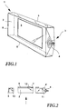
- Fig. 1 shows the picture holder in a view from the top left front.
- the picture holder points a glass plate 2.
- a light source 3 the partially broken open to the view of the illuminant 4, in this case a Light bulb to release.
- the lamp is fastened light-tight on the left side surface, so that light can only enter the side surface. To get a good light output achieve, it makes sense to provide the illuminant with a reflector on the inside.
- the Light source 3 are also energy supply devices, for example Batteries and control elements, for example on and off switches, which are shown in FIG. 1 are not shown for the sake of simplicity.
- the other side surfaces through which no light is introduced into the front panel are provided with a reflective lacquer layer 5, so that no through these side surfaces Light can leak.
- the illuminant 3 can also face in be mirrored in the area in which no light is introduced into the front panel 2 or in which the side surface is not covered by the illuminant 3 and its devices.
- the light is held in the front panel 2 by the mirrored side surfaces, and can only exit through the front and rear of the front panel.
- the front plate 2 consists of very thick glass in the first embodiment.
- the lower side surface forms a base on which the picture holder stands independently can be set up without tipping over.
- thick Front plate makes sense from a design point of view.
- Fig. 2 shows a horizontal section through the embodiment of Fig. 1. Between the front plate 2 and the picture 6 is the pressure sensitive adhesive that the Adhesions- and Light guide layer 7 forms. Furthermore, a mirrored, parabolic reflector 4 ' shown, through which the light can be coupled into the side surface without loss.
- the pressure sensitive adhesive completely covers a portion of the back of the front panel that is in Shape and area corresponds to Figure 6. As a result, there are no protruding adhesive surfaces existing, which may be due to dust or the like after long use can pollute.
- the pressure sensitive adhesive is wound in the form of a tape in the original state.
- the thickness of the double-sided adhesive, flowable tape is 1 mm.
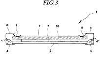
- the second embodiment has a frame 8 which the front panel 2 on the Front and surrounds like a frame on the side surfaces.
- Illuminant 4 mounted in the frame 8 .
- Light-emitting diodes are used here that emit white light.
- reflectors 4 'on the two vertically extending, opposite Side surfaces the light is fed into the front panel 2.
- the portions of the side surfaces on which no light in the front panel 2 is fed mirrored by a mirror film.
- the clip-like spring elements 9 are attached to the frame.
- the clip-like spring elements 9 are supported on one side on the frame 8 and are on the other Provide side with a hold-down that against a portion of the rear wall 10 as a counterhold.
- the frame can be made of aesthetically demanding and resistant materials such as aluminum, titanium or the like, be made or coated, for example anodized, so as to preserve its appearance even after long use and not to oxidize.
- FIG. 2 shows a light beam 11 which leaves the illuminant 4 at an angle, in which he can enter through the side surface in the front panel 2 without the Interface to be reflected.
- a Adhesion and light guide layer is provided, and on the front of the light beam 11 reflected by total reflection so that it does not leave the front panel 2 can.
- the light beam strikes the back of the front panel in an area with a Adhesion and light guide layer 7 is provided, so it is not reflected on the back surface, but through the adhesion and light guide layer 7 to the image surface directed as indicated by line 12.
- the pressure sensitive adhesive which the Adhesion layer 7 forms the refractive index by adding such refractive index the front panel 2 adapted that the light even at high angles of incidence to the interface between the adhesion and light guide layer 7 and the front plate 2 Image surface forwarded and the image surface is well illuminated.
- the adhesion and light guide layer 7 should be evenly on the back be applied to the front panel so that there are no air bubbles and inclusions, through which the light is refracted.
- the example of the light beam 14 shows that the mirrored side faces 5 the light is also completely reflected back into the front panel 2.
- the adhesion and light guide layer 7 is applied without gaps only in the area of the image 6.
- the area and form of this application can be based on the common image formats for Orient photographs.
- the dimensions of the picture holder or the Front plate correspond to the dimensions of the common photo formats. In this case can the entire back surface of the front panel 2 with an adhesion and light guide layer be provided.
Landscapes
- Physics & Mathematics (AREA)
- Engineering & Computer Science (AREA)
- General Engineering & Computer Science (AREA)
- General Physics & Mathematics (AREA)
- Optics & Photonics (AREA)
- Illuminated Signs And Luminous Advertising (AREA)
- Planar Illumination Modules (AREA)
Abstract
Description
- Fig. 1
- eine perspektivische Ansicht eines ersten Ausführungsbeispiels des erfindungsgemäßen beleuchteten Bilderhalters:
- Fig. 2
- einen abschnittsweisen Querschnitt durch das Ausführungsbeispiel der Fig. 1 durch eine Frontplatte, Adhäsionsschicht und ein Bild;
- Fig. 3
- einen Horizontalschnitt durch ein zweites Ausführungsbeispiel des erfindungsgemäßen beleuchteten Bilderhalters.
Claims (18)
- Beleuchteter Bilderhalter zur Darstellung von Bildmotiven, mit einer durchsichtigen Frontplatte, durch die hindurch ein Bild einsehbar ist, und einer an einer Seitenfläche der Frontplatte angeordneten Lichtquelle, deren Licht durch die Seitenfläche in die Frontplatte geleitet ist, dadurch gekennzeichnet, daß zwischen Bild (6) und Rückseite der Frontplatte (2) eine durchsichtige Adhäsionsschicht (7) angeordnet ist, durch die das Bild (6) auswechselbar an der Frontplatte (2) gehalten ist und die als Lichtleiterschicht (7) mit einem Brechungsindex ausgestaltet ist, der größer ist als der Brechungsindex von Luft, wodurch das Licht der Lichtquelle (4) von der Frontplatte (2) durch die Adhäsionsschicht (7) auf die Bildoberfläche geleitet ist und das Bild beleuchtet.
- Beleuchteter Bilderhalter nach Anspruch 1, dadurch gekennzeichnet, daß die Seitenflächen an den Abschnitten (5), an denen kein Licht der Lichtquelle (4) in die Frontplatte (2) eingeleitet ist, verspiegelt sind.
- Beleuchteter Bilderhalter nach einem der obengenannten Ansprüche, dadurch gekennzeichnet, daß die Adhäsionsschicht (7) einen Brechungsindex aufweist, der in etwa dem Brechungsindex des Werkstoffes der Frontplatte (2) entspricht.
- Beleuchteter Bilderhalter nach einem der obengenannten Ansprüche, dadurch gekennzeichnet, daß die Adhäsionsschicht (7) einen Brechungsindex zwischen 1,3 und 2,5, vorzugsweise zwischen 1,3 und 1,7, aufweist.
- Beleuchteter Bilderhalter nach einem der obengenannten Ansprüche, dadurch gekennzeichnet, daß das Verhältnis des Brechungsindizes von Frontplatte (2) und Adhäsionsschicht (7) im Bereich von 0,8 bis 1,2, vorzugsweise zwischen 0,9 und 1,1, liegt.
- Beleuchteter Bilderhalter nach einem der obengenannten Ansprüche, dadurch gekennzeichnet, daß die Adhäsionsschicht (7) einen zusammenhängenden Abschnitt der Rückseite der Frontplatte (2) lückenlos bedeckt.
- Beleuchteter Bilderhalter nach einem der obengenannten Ansprüche, dadurch gekennzeichnet, daß die Dicke der Adhäsionsschicht (7) zwischen 0,1 mm und 1 mm, vorzugsweise zwischen 0,3 mm und 0,7 mm beträgt.
- Beleuchteter Bilderhalter nach einem der obengenannten Ansprüche, dadurch gekennzeichnet, daß die Adhäsionsschicht (7) auf einem Abschnitt der Rückseite der Frontplatte (2) aufgetragen ist, dessen Fläche und/oder Form im wesentlichen der Fläche und/oder Form des Bildes (6) entspricht.
- Beleuchteter Bilderhalter nach einem der obengenannten Ansprüche, dadurch gekennzeichnet, daß die Abmessungen der Rückseite der Frontplatte (2) in etwa den Abmessungen der Bildoberfläche (6) entsprechen.
- Beleuchteter Bilderhalter nach einem der Ansprüche 1 und 2, dadurch gekennzeichnet, daß die Frontplatte (2) aus einem klarsichtigen Werkstoff, wie beispielsweise Glas oder Acrylglas, hergestellt ist.
- Beleuchteter Bilderhalter nach einem der obengenannten Ansprüche, dadurch gekennzeichnet, daß die Adhäsionsschicht (7) aus einem Haftklebstoff gebildet ist, der bei Raumtemperatur permanent klebrig und klebfähig ist sowie eine geringe Substratspezifität aufweist.
- Beleuchteter Bilderhalter nach einem der obengenannten Ansprüche, dadurch gekennzeichnet, daß der Haftklebstoff ein Basispolymer umfaßt, welches unter Polyacrylaten, Polyestern, Polychloroprenen, Polyisobutenen, Plyvinyletheren und Polyurethanen ausgewählt ist und/oder Mischungen davon umfaßt.
- Beleuchteter Bilderhalter nach einem der obengenannten Ansprüche, dadurch gekennzeichnet, daß zum Einstellen des Brechungsindizes des Haftklebstoffs dem Haftklebstoff Zusätze wie beispielsweise Weichmacher und/oder Harze und/oder Antioxidantien zugemischt sind.
- Beleuchteter Bilderhalter nach einem der obengenannten Ansprüche, dadurch gekennzeichnet, daß die Lichtquelle (4) eine Glühlampe und/oder eine Gasentladungslampe und/oder eine Leuchtdiode ist.
- Beleuchteter Bilderhalter nach einem der obengenannten Ansprüche, dadurch gekennzeichnet, daß zumindest die Seitenflächen der Frontplatte (2) mit einem Rahmen (8) umgeben sind.
- Beleuchteter Bilderhalter nach einem der obengenannten Ansprüche, dadurch gekennzeichnet, daß Das Leuchtmittel (4) im Rahmen (8) integriert ist.
- Beleuchteter Bilderhalter nach einem der obengenannten Ansprüche, dadurch gekennzeichnet, daß zumindest ein Federelement (9) mit einem Niederhalter und einem Gegenhalter vorgesehen ist, wobei durch den Niederhalter das Bild (6) in Richtung der Adhäsionsschicht (7) gedrückt ist und der Gegenhalter sich an der Frontplatte (2) zumindest mittelbar abstützt.
- Beleuchteter Bilderhalter nach einem der obengenannten Ansprüche, dadurch gekennzeichnet, daß eine Rückwand (10) zum gleichmäßigen Andrücken des Bildes an die Adhäsionsschicht zwischen Federelement (9) und Bild angeordnet ist.
Applications Claiming Priority (2)
| Application Number | Priority Date | Filing Date | Title |
|---|---|---|---|
| DE1998130151 DE19830151C1 (de) | 1998-07-06 | 1998-07-06 | Beleuchteter Bilderhalter |
| DE19830151 | 1998-07-06 |
Publications (2)
| Publication Number | Publication Date |
|---|---|
| EP0972475A2 true EP0972475A2 (de) | 2000-01-19 |
| EP0972475A3 EP0972475A3 (de) | 2001-09-26 |
Family
ID=7873127
Family Applications (1)
| Application Number | Title | Priority Date | Filing Date |
|---|---|---|---|
| EP99106954A Withdrawn EP0972475A3 (de) | 1998-07-06 | 1999-04-08 | Beleuchteter Bilderhalter |
Country Status (2)
| Country | Link |
|---|---|
| EP (1) | EP0972475A3 (de) |
| DE (1) | DE19830151C1 (de) |
Families Citing this family (5)
| Publication number | Priority date | Publication date | Assignee | Title |
|---|---|---|---|---|
| DE20007314U1 (de) | 2000-04-20 | 2000-07-13 | Freund Walter | Dekorationsobjekt nach Art eines Bildes |
| DE20106200U1 (de) * | 2001-04-10 | 2001-06-21 | Holz, Jürgen, 50825 Köln | Darreichungsvorrichtung für Speisen |
| DE20202319U1 (de) | 2002-02-14 | 2002-05-16 | Geiberger Christoph | Beleuchteter Wechselrahmen |
| DE102009011993B4 (de) * | 2009-03-06 | 2010-12-02 | Behr-Hella Thermocontrol Gmbh | Halter für ein Anzeigeelement |
| DE202012101316U1 (de) * | 2012-04-12 | 2013-07-15 | Zumtobel Lighting Gmbh | Anordnung zur Lichtabgabe mit flächigem Lichtleitelement |
Citations (1)
| Publication number | Priority date | Publication date | Assignee | Title |
|---|---|---|---|---|
| DE8229147U1 (de) | 1983-10-06 | Heck, Friedrich, 6078 Neu Isenburg | Vorrichtung zur optischen Darstellung eines Bildmotivs |
Family Cites Families (13)
| Publication number | Priority date | Publication date | Assignee | Title |
|---|---|---|---|---|
| US1843980A (en) * | 1931-10-01 | 1932-02-09 | Hotchner Fred | Changeable luminous display sign |
| US2772997A (en) * | 1950-02-13 | 1956-12-04 | Richard C Webster | Illuminated and edge-lighted articles and methods of making same |
| US3780463A (en) * | 1972-05-15 | 1973-12-25 | L Aronoff | Illuminated displays and illuminaries |
| US4385343A (en) * | 1978-12-26 | 1983-05-24 | Plumly George W | Edge lighted devices |
| AU5232696A (en) * | 1988-06-23 | 1996-07-18 | Wilson, Ian Brownlie | Display apparatus |
| DE3919925A1 (de) * | 1989-06-19 | 1990-12-20 | Inotec Gmbh Ges Fuer Innovativ | Beleuchtete, anzeigeeinheit, insbesondere hausnummer, verkehrsschild, werbetraeger |
| DE68927640D1 (de) * | 1989-09-13 | 1997-02-20 | Tradebest Int Corp | Autonome, visuell anziehende Vorrichtung mit einem über den Kanten beleuchteten Paneel |
| DE9217383U1 (de) * | 1992-12-19 | 1993-02-18 | Roehm Gmbh, 6100 Darmstadt | Lichtleitplatten zur Beleuchtung auswechselbarer Informationen |
| GB2304960B (en) * | 1995-09-08 | 1997-11-05 | Thor Daniel Hjaltason | Illuminated sign and sign plate therefor |
| FR2741180B1 (fr) * | 1995-11-10 | 1998-02-06 | Epsilon | Panneau luminescent |
| GB2309111A (en) * | 1996-01-09 | 1997-07-16 | Charles Andrew Cockersole | Display apparatus |
| FR2744519A1 (fr) * | 1996-02-07 | 1997-08-08 | Berque Emmanuel | Dispositif de signalisation lumineuse et retroreflechissante |
| GB2316216B (en) * | 1996-08-06 | 2000-09-06 | Morton Graham | Illuminated displays |
-
1998
- 1998-07-06 DE DE1998130151 patent/DE19830151C1/de not_active Expired - Fee Related
-
1999
- 1999-04-08 EP EP99106954A patent/EP0972475A3/de not_active Withdrawn
Patent Citations (1)
| Publication number | Priority date | Publication date | Assignee | Title |
|---|---|---|---|---|
| DE8229147U1 (de) | 1983-10-06 | Heck, Friedrich, 6078 Neu Isenburg | Vorrichtung zur optischen Darstellung eines Bildmotivs |
Also Published As
| Publication number | Publication date |
|---|---|
| DE19830151C1 (de) | 1999-04-29 |
| EP0972475A3 (de) | 2001-09-26 |
Similar Documents
| Publication | Publication Date | Title |
|---|---|---|
| DE2716196A1 (de) | Schaustellungseinrichtung | |
| CH269843A (de) | Biegsames, mindestens grösstenteils durchsichtiges Blattmaterial. | |
| DE4122118C2 (de) | Schriftfeldbeleuchtung | |
| DE19830151C1 (de) | Beleuchteter Bilderhalter | |
| DE9217383U1 (de) | Lichtleitplatten zur Beleuchtung auswechselbarer Informationen | |
| DE10064703B4 (de) | Sandwichartiges Plattenelement | |
| DE8209696U1 (de) | Leuchtelement | |
| DE69117060T2 (de) | Fluoreszierende klebefolie | |
| DE3617784C2 (de) | ||
| DE19520697A1 (de) | Türschild oder -tafel für visuelle Informationen | |
| DE10355120A1 (de) | Werbeschild | |
| DE202009003573U1 (de) | Beleuchtetes Schild | |
| DE202004017737U1 (de) | Leuchtwand | |
| DE2328467B1 (de) | Armaturentafel für Kraftfahrzeuge | |
| DE488171C (de) | Vorrichtung zum Beleuchten von Gegenstaenden unterschiedlicher Art von deren Rande aus, besonders fuer Schaustellung oder Reklamezwecke | |
| AT513336B1 (de) | Vorrichtung zur Präsentation von Informationsträgern | |
| DE202005003941U1 (de) | Multidekorform | |
| DE20114026U1 (de) | Schild | |
| DE2657674C3 (de) | Anordnung für Leuchtanzeigen von Bedienelementen | |
| DE10037330A1 (de) | Bildhalter | |
| CH164393A (de) | Reklameschaukasten. | |
| DE4205136A1 (de) | Lichtleitscheibe mit auswechselbarem transparent | |
| DE665345C (de) | Vorrichtung zur Vorfuehrung farbiger Lichtreklamen in Schaufenstern | |
| DE102004059084A1 (de) | Reflectographics | |
| DE29519778U1 (de) | Scheibenleuchte für schnell wechselbare Hinweiselemente |
Legal Events
| Date | Code | Title | Description |
|---|---|---|---|
| PUAI | Public reference made under article 153(3) epc to a published international application that has entered the european phase |
Free format text: ORIGINAL CODE: 0009012 |
|
| AK | Designated contracting states |
Kind code of ref document: A2 Designated state(s): AT BE CH CY DE DK ES FI FR GB GR IE IT LI LU MC NL PT SE |
|
| AX | Request for extension of the european patent |
Free format text: AL;LT;LV;MK;RO;SI |
|
| PUAL | Search report despatched |
Free format text: ORIGINAL CODE: 0009013 |
|
| AK | Designated contracting states |
Kind code of ref document: A3 Designated state(s): AT BE CH CY DE DK ES FI FR GB GR IE IT LI LU MC NL PT SE |
|
| AX | Request for extension of the european patent |
Free format text: AL;LT;LV;MK;RO;SI |
|
| RIC1 | Information provided on ipc code assigned before grant |
Free format text: 7A 47G 1/06 A, 7F 21V 8/00 B, 7G 09F 13/18 B |
|
| STAA | Information on the status of an ep patent application or granted ep patent |
Free format text: STATUS: THE APPLICATION IS DEEMED TO BE WITHDRAWN |
|
| AKX | Designation fees paid | ||
| 18D | Application deemed to be withdrawn |
Effective date: 20010501 |
|
| REG | Reference to a national code |
Ref country code: DE Ref legal event code: 8566 |