EP0972599A2 - Foret pour métal à plaquette coupe avec chevauchement des arêtes de coupe - Google Patents
Foret pour métal à plaquette coupe avec chevauchement des arêtes de coupe Download PDFInfo
- Publication number
- EP0972599A2 EP0972599A2 EP99110707A EP99110707A EP0972599A2 EP 0972599 A2 EP0972599 A2 EP 0972599A2 EP 99110707 A EP99110707 A EP 99110707A EP 99110707 A EP99110707 A EP 99110707A EP 0972599 A2 EP0972599 A2 EP 0972599A2
- Authority
- EP
- European Patent Office
- Prior art keywords
- radially
- cutting
- cutting edge
- drill
- cutting edges
- Prior art date
- Legal status (The legal status is an assumption and is not a legal conclusion. Google has not performed a legal analysis and makes no representation as to the accuracy of the status listed.)
- Granted
Links
Images


Classifications
-
- B—PERFORMING OPERATIONS; TRANSPORTING
- B23—MACHINE TOOLS; METAL-WORKING NOT OTHERWISE PROVIDED FOR
- B23B—TURNING; BORING
- B23B51/00—Tools for drilling machines
- B23B51/02—Twist drills
-
- B—PERFORMING OPERATIONS; TRANSPORTING
- B23—MACHINE TOOLS; METAL-WORKING NOT OTHERWISE PROVIDED FOR
- B23B—TURNING; BORING
- B23B51/00—Tools for drilling machines
- B23B51/04—Drills for trepanning
- B23B51/0486—Drills for trepanning with lubricating or cooling equipment
-
- B—PERFORMING OPERATIONS; TRANSPORTING
- B23—MACHINE TOOLS; METAL-WORKING NOT OTHERWISE PROVIDED FOR
- B23B—TURNING; BORING
- B23B2240/00—Details of connections of tools or workpieces
- B23B2240/08—Brazed connections
-
- B—PERFORMING OPERATIONS; TRANSPORTING
- B23—MACHINE TOOLS; METAL-WORKING NOT OTHERWISE PROVIDED FOR
- B23B—TURNING; BORING
- B23B2251/00—Details of tools for drilling machines
- B23B2251/20—Number of cutting edges
- B23B2251/202—Three cutting edges
-
- B—PERFORMING OPERATIONS; TRANSPORTING
- B23—MACHINE TOOLS; METAL-WORKING NOT OTHERWISE PROVIDED FOR
- B23B—TURNING; BORING
- B23B2251/00—Details of tools for drilling machines
- B23B2251/28—Arrangement of teeth
- B23B2251/287—Cutting edges having different lengths
-
- B—PERFORMING OPERATIONS; TRANSPORTING
- B23—MACHINE TOOLS; METAL-WORKING NOT OTHERWISE PROVIDED FOR
- B23B—TURNING; BORING
- B23B2251/00—Details of tools for drilling machines
- B23B2251/48—Chip breakers
-
- B—PERFORMING OPERATIONS; TRANSPORTING
- B23—MACHINE TOOLS; METAL-WORKING NOT OTHERWISE PROVIDED FOR
- B23B—TURNING; BORING
- B23B2251/00—Details of tools for drilling machines
- B23B2251/50—Drilling tools comprising cutting inserts
-
- B—PERFORMING OPERATIONS; TRANSPORTING
- B23—MACHINE TOOLS; METAL-WORKING NOT OTHERWISE PROVIDED FOR
- B23B—TURNING; BORING
- B23B2251/00—Details of tools for drilling machines
- B23B2251/56—Guiding pads
-
- B—PERFORMING OPERATIONS; TRANSPORTING
- B23—MACHINE TOOLS; METAL-WORKING NOT OTHERWISE PROVIDED FOR
- B23B—TURNING; BORING
- B23B51/00—Tools for drilling machines
- B23B51/06—Drills with lubricating or cooling equipment
- B23B51/063—Deep hole drills, e.g. ejector drills
-
- Y—GENERAL TAGGING OF NEW TECHNOLOGICAL DEVELOPMENTS; GENERAL TAGGING OF CROSS-SECTIONAL TECHNOLOGIES SPANNING OVER SEVERAL SECTIONS OF THE IPC; TECHNICAL SUBJECTS COVERED BY FORMER USPC CROSS-REFERENCE ART COLLECTIONS [XRACs] AND DIGESTS
- Y10—TECHNICAL SUBJECTS COVERED BY FORMER USPC
- Y10T—TECHNICAL SUBJECTS COVERED BY FORMER US CLASSIFICATION
- Y10T408/00—Cutting by use of rotating axially moving tool
- Y10T408/89—Tool or Tool with support
- Y10T408/905—Having stepped cutting edges
- Y10T408/906—Axially spaced
Definitions
- the present invention relates to a drill and a cutting insert adapted for use in metal cutting.
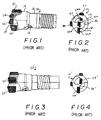
- a conventional drill 10 depicted in Figs. 1 and 2 includes a steel body having a hollow shank 12 and a head 14 disposed at a front end thereof.
- the shank 12 has a central passageway 16 extending axially forwardly from a rear end of the shank and communicating with a pair of throats 18, 20 formed in a front face 22 of the head 14.
- Brazed in recesses formed in the front face are three carbide cutting inserts 24, 26, 28, two of which 24 and 26 are arranged at the throat 18.
- the third insert 28 is arranged at the throat 20.
- the inserts form respective cutting edges 24A, 26A, 28A that are arranged substantially on a diametrical line as viewed in Fig. 2.
- Chips that are cut become entrained in cooling liquid conducted forwardly through the central passageway 16 and the throats 18, 20 and are exhausted rearwardly within a gap formed between the drill and the wall of the bore being drilled.
- a pair of guide pads 30, 32 is provided in a side wall of the head 14 to guide the drill.
- FIG. 3 and 4 Another prior art drill 10' is depicted in Figs. 3 and 4 wherein only two inserts 24' and 28' are employed. Such a drill may be employed to drill smaller bores than the drill of Figs. 1-2.
- a drilling operation produces a chip flow which tends to wear away portions of the front face of the steel head 14 situated between the cutting inserts, i.e., the portions 30, 32 shown in Fig. 2 and the portion 30' shown in Fig. 4.
- the portion 30' shown in Fig. 4 seems, in practice, to be particularly susceptible to such wear.
- erosion of the steel body can lead to a collapsing of the drill.
- the invention relates to a metal cutting drill comprising a drill body and an insert brazed thereto.
- the drill body includes a shank, and a head disposed at a forward end of the shank.
- a passageway extends longitudinally forwardly through the shank and is connected to throats extending rearwardly from a front face of the head.
- a recess is formed in the front face, the recess overlapping a longitudinal axis of the drill body.
- the insert is formed of a harder material than the drill body (e.g., carbide).
- the insert is brazed in the recess and forms a plurality of spaced-apart cutting edges disposed on opposite sides of the axis and situated circumferentially behind respective ones of the throats. The cutting edges overlap each other radially during a drilling operation. One of the cutting edges projects radially outwardly beyond a side face of the head, and another of the cutting edges terminates radially inwardly of the side face.
- the invention also relates to a cutting insert per se which is adapted for use in a metal cutting drill.
- the insert comprises a carbide body having oppositely facing sides, and a front surface. Each side is beveled adjacent the front surface whereby an intersection between a first of the bevels and the front surface forms at least one cutting edge facing in a first direction. An intersection between a second of the bevels and the front surface forms a second cutting edge facing in a second direction opposite to the first direction.
- the first and second bevels are intersected by a common plane passing through the front surface in a direction parallel to the cutting edges.
- a drill 40 includes a steel drill body similar to that described in connection with Figs. 1-4 in that the drill body includes a hollow shank 42 and a head 44 disposed at a front end thereof.
- the shank has a central coolant passageway 46 extending axially forwardly from a rear end of the shank and communicating with a pair of large and small throats 48, 50 that converge rearwardly from a front face 52 of the head 44.
- a cutting insert 60 which is brazed in a recess 54 formed in the front face 52, includes a body formed of a harder material than the steel drill body, e.g., carbide.
- the insert body is slightly longer than the recess 54 in the radial direction of the drill, whereby a radial outer edge 68 of the insert projects radially outwardly beyond a side face 56 of the head 44.
- a radially inner edge 70 of the insert is spaced radially inwardly from the side face 56 on an opposite side of a central axis A of the drill from the outer edge 68.
- the insert overlaps the axis A.
- the insert includes three spaced-apart cutting edges, namely, a radially outer cutting edge 62, a radially inner cutting edge 64 and a central cutting edge 66.
- the insert includes a pair of opposing sides 69, 71 and a front surface 73. Portions 80, 82 of the sides located adjacent the front surface 73 are beveled whereby two of the spaced-apart cutting edges 62, 66 are formed by an intersection of the bevel 80 and the front surface 73, and the third spaced-apart cutting edge 64 is formed by an intersection of the other bevel 82 and the front surface 73. That cutting edge 64 faces in a tangential direction T opposite to the tangential direction T' in which the cutting edges 62, 66 face.
- Both of the bevels 80, 82 are intersected by a common plane P which passes through the front surface 73 in a direction substantially parallel to the cutting edges 62, 64, 66.
- the outer and inner cutting edges 62, 64 are flared longitudinally rearwardly and radially outwardly (i.e. away from the axis A as the insert is viewed in profile-see Fig. 5).
- the center cutting edge 66 is flared longitudinally rearwardly and radially inwardly (i.e., toward the axis A). The center cutting edge 66 radially overlaps the axis A.
- the forward end 72 of the center edge 66 is situated farther forwardly than the forwardmost points of either of the other edges 62, 64 as can be seen in Fig. 5.
- the forward end 76 of the inner edge 64 is situated farther forwardly than the forwardmost point on the outer edge 62.
- the inner edge 64 radially overlaps a region 78 disposed between the outer and center edges 62, 66, whereby the three cutting edges cooperate to cut an entire diameter of a bore.
- the outer and center edges 62, 66 are situated circumferentially behind the large throat 48 with reference to the direction of drilling R, whereas the inner edge 64 is situated circumferentially behind the small throat 50.
- chips cut by the edges 62, 66 are flushed by fluid exiting the throat 48, and chips cut by the edge 64 are flushed by fluid exiting the throat 50.
- the bevels 80, 82 function as chip-guiding surfaces.
- Two guide pads 86, 88 are provided on the side surface 56 to guide the drill, as is conventional.
- FIG. 10-14 A second preferred embodiment of the invention is depicted in Figs. 10-14 which would be expected to cut smaller-diameter bores than the drill according to Figs. 5-9.
- That second embodiment includes a drill 40' generally similar to the earlier described drill 40', and which includes two throats 48', 50'.
- Mounted in a recess 54' of the drill body is a cutting insert 100 which forms only two cutting edges 102, 104, namely a radially outer cutting edge 102 and a radially inner cutting edge 104.
- Those cutting edges are formed by the intersections of bevels 120, 122 with a front surface 124.
- Those bevels 120, 122 lie in a common plane P which passes through the front surface 124 in a direction parallel to the cutting edges 102, 104.
- the outer cutting edge 102 is flared longitudinally rearwardly and radially outwardly.
- the inner cutting edge 104 is flared longitudinally rearwardly and radially inwardly.
- the inner cutting edge 104 radially overlaps the axis A.
- the radially inner end 110 of the outer cutting edge 102 is situated longitudinally forwardly of the inner cutting edge 104.
- the outer cutting edge 104 projects radially beyond a side face 56' of the drill body, and the outer end 108 of the inner cutting edge radially overlaps the cutting path of the outer edge during a drilling operation, so the two cutting edges 102, 104 together form the diameter of the hole being drilled.
- the cutting edges 102, 104 are situated circumferentially behind the throats 48', 50', respectively, with reference to the direction of drilling R. Thus, chip cut by the edges 102, 104 are flushed by fluid exiting the throats 48', 50', respectively.
- Bevel portions 112, 114 of the insert body situated longitudinally rearwardly of the respective cutting edges 102, 104 are flared longitudinally rearwardly and circumferentially forwardly to serve as chip faces.
Landscapes
- Engineering & Computer Science (AREA)
- Mechanical Engineering (AREA)
- Drilling Tools (AREA)
- Earth Drilling (AREA)
Applications Claiming Priority (2)
| Application Number | Priority Date | Filing Date | Title |
|---|---|---|---|
| US115636 | 1998-07-15 | ||
| US09/115,636 US6019553A (en) | 1998-07-15 | 1998-07-15 | Metal cutting drill with insert having radially overlapping cutting edges |
Publications (3)
| Publication Number | Publication Date |
|---|---|
| EP0972599A2 true EP0972599A2 (fr) | 2000-01-19 |
| EP0972599A3 EP0972599A3 (fr) | 2002-11-13 |
| EP0972599B1 EP0972599B1 (fr) | 2005-12-07 |
Family
ID=22362575
Family Applications (1)
| Application Number | Title | Priority Date | Filing Date |
|---|---|---|---|
| EP99110707A Expired - Lifetime EP0972599B1 (fr) | 1998-07-15 | 1999-06-03 | Foret pour métal à plaquette coupe avec chevauchement des arêtes de coupe |
Country Status (9)
| Country | Link |
|---|---|
| US (1) | US6019553A (fr) |
| EP (1) | EP0972599B1 (fr) |
| JP (1) | JP2000033508A (fr) |
| KR (2) | KR100597499B1 (fr) |
| CN (1) | CN1110393C (fr) |
| AT (1) | ATE311952T1 (fr) |
| BR (1) | BR9902724A (fr) |
| DE (1) | DE69928728T2 (fr) |
| IN (1) | IN192122B (fr) |
Cited By (2)
| Publication number | Priority date | Publication date | Assignee | Title |
|---|---|---|---|---|
| EP1386684A1 (fr) * | 2002-06-14 | 2004-02-04 | Diager | Plaquette de coupe pour foret, et outil de percage utilisant cette plaquette |
| USD1009108S1 (en) | 2020-09-21 | 2023-12-26 | Kyocera Unimerco Tooling A/S | Drill |
Families Citing this family (20)
| Publication number | Priority date | Publication date | Assignee | Title |
|---|---|---|---|---|
| US6582164B1 (en) | 2002-02-25 | 2003-06-24 | Kennametal Inc. | Roller twist drill |
| SE0301456D0 (sv) * | 2003-05-20 | 2003-05-20 | Sandvik Ab | Ett eggbärande borrkropp, och ett förfarande för tillverkning av samt ett borrverktyg innefattande en dylik borrkropp |
| SE526676C2 (sv) * | 2003-05-20 | 2005-10-25 | Sandvik Intellectual Property | Eggbärande borrkropp för långhålsborrning med eggar förfärdigade i ett stycke med borrkroppen |
| WO2009006042A1 (fr) * | 2007-06-29 | 2009-01-08 | Allied Machine & Engineering Corp. | Système de foret à éjecteur |
| IL187034A0 (en) * | 2007-10-30 | 2008-02-09 | Iscar Ltd | Cutting tool |
| DE102010018959A1 (de) * | 2010-04-23 | 2011-10-27 | Tbt Tiefbohrtechnik Gmbh + Co | Bohrkopf für ein Tiefbohrwerkzeug zum BTA-Tiefbohren und Tiefbohrwerkzeug |
| EP2711114B1 (fr) * | 2011-05-16 | 2021-09-08 | botek Präzisionsbohrtechnik GmbH | Tête de forage pour le perçage de trous profonds |
| US9370825B2 (en) | 2011-07-22 | 2016-06-21 | Kennametal India Limited | Indexable drill insert |
| DE102012012980B4 (de) | 2011-07-22 | 2019-10-17 | Kennametal India Ltd. | Bohrwerkzeug |
| DE102012014092B4 (de) | 2011-07-22 | 2020-12-17 | Kennametal India Ltd. | Indexierbarer Bohreinsatz sowie Bohrkörper mit indexierbarem Bohreinsatz |
| CN102672246A (zh) * | 2012-05-23 | 2012-09-19 | 上海嘉仕久企业发展有限公司 | 用于钻多层板的u钻 |
| CN103447591B (zh) | 2012-05-28 | 2020-02-28 | 钴碳化钨硬质合金印度有限公司 | 四角形的可转位的钻头镶片 |
| WO2014116571A1 (fr) | 2013-01-23 | 2014-07-31 | Kennametal India Limited | Plaquette amovible indexée et outil de coupe rotatif la mettant en œuvre |
| SE537475C2 (sv) * | 2013-09-27 | 2015-05-12 | Sandvik Intellectual Property | Långhålsborrverktyg med vinklad fasyta i anslutning till skäreggen |
| US10646985B2 (en) | 2015-09-11 | 2020-05-12 | The United States Of America, As Represented By The Secretary Of The Navy | Method and apparatus for limiting equipment burden when penetrating a mixed or composite material structure including metal utilizing a hammer-drill |
| WO2019087656A1 (fr) * | 2017-10-30 | 2019-05-09 | 京セラ株式会社 | Outil de coupe et procédé de fabrication de produits découpés |
| CN108927555A (zh) * | 2018-09-11 | 2018-12-04 | 浙江甬岭数控刀具有限公司 | 可转位深孔钻 |
| CN112077370B (zh) | 2019-06-13 | 2024-10-01 | 肯纳金属印度有限公司 | 可转位钻头刀片 |
| JP6835194B1 (ja) * | 2019-12-12 | 2021-02-24 | 株式会社タンガロイ | 穴あけ工具 |
| CN115703157A (zh) | 2021-08-17 | 2023-02-17 | 肯纳金属印度有限公司 | 具有冷却剂系统的可转位钻头组件 |
Family Cites Families (26)
| Publication number | Priority date | Publication date | Assignee | Title |
|---|---|---|---|---|
| GB550306A (en) * | 1942-01-19 | 1943-01-01 | Herbert Ltd A | Improvements relating to drills and to cutters therefor |
| GB842133A (en) * | 1957-12-04 | 1960-07-20 | Wickman Ltd | Metal cutting tools |
| DE1477708A1 (de) * | 1962-04-12 | 1969-07-24 | Sandco Ltd | Spanabhebend arbeitender Drehbohrer |
| US3816018A (en) * | 1972-10-06 | 1974-06-11 | Tatra Np | Boring bit |
| DE2316762A1 (de) * | 1973-04-04 | 1974-10-17 | Heller Geb | Bohrwerkzeug mit innerem abfuehrkanal |
| GB1556661A (en) * | 1976-10-19 | 1979-11-28 | Gkn Transmissions Ltd | Drill heads and methods of drilling |
| SE411310B (sv) * | 1976-11-17 | 1979-12-17 | Sandvik Ab | Borr, foretredesvis med vendsker |
| US4143723A (en) * | 1977-10-04 | 1979-03-13 | Schmotzer Norman H | Carbide tipped drill bit for boring holes in concrete and steel |
| US4120601A (en) * | 1977-10-06 | 1978-10-17 | Erickson Tool Company | Spade drill |
| DE2903814C2 (de) * | 1979-02-01 | 1982-08-19 | Mapal Fabrik für Präzisionswerkzeuge Dr.Kress KG, 7080 Aalen | Bohrkopf |
| US4620822A (en) * | 1982-03-17 | 1986-11-04 | General Electric Company | Flat bottom hole drill |
| JPS5973215A (ja) * | 1982-10-18 | 1984-04-25 | Nippon Yakin:Kk | ドリル、特に深孔穿設用ドリル |
| US4618296A (en) * | 1983-09-14 | 1986-10-21 | Gte Valeron Corporation | Cutting tool and insert therefor |
| DE3419350A1 (de) * | 1984-05-24 | 1985-11-28 | Dieter 4100 Duisburg Böhmer | Bohrkopf zum tieflochbohren bzw. kernbohren |
| SE455676B (sv) * | 1984-11-12 | 1988-08-01 | Sandvik Ab | Korthalsborr, samt sker derfor |
| SE457696B (sv) * | 1987-05-21 | 1989-01-23 | Sandvik Ab | Borr foer paketborrning |
| DE8717548U1 (de) * | 1987-05-21 | 1989-03-09 | Heule, Heinrich, Balgach | Schneidmesser zum beidseitigen Entgraten der Kanten von Durchgangsbohrungen |
| JP2572128B2 (ja) * | 1989-05-16 | 1997-01-16 | 富士精工株式会社 | 高速高送り用バニシングドリルリーマ |
| DE69117268T2 (de) * | 1990-11-26 | 1996-08-14 | De Beers Ind Diamond | Schneideinsatz für ein rotierendes Schneidwerkzeug |
| JPH04201106A (ja) * | 1990-11-30 | 1992-07-22 | Masao Kubota | ドリル |
| SE467727B (sv) * | 1991-01-28 | 1992-09-07 | Sandvik Ab | Borr med minst tvaa skaer, samt med symmetrisk borrspets och olika laanga skaereggar |
| US5184925A (en) * | 1992-01-10 | 1993-02-09 | Kennametal Inc. | Insert and insert support bar |
| SE507842C2 (sv) * | 1992-09-24 | 1998-07-20 | Sandvik Ab | Borr |
| DE4239257C2 (de) * | 1992-11-21 | 1998-02-26 | Mapal Fab Praezision | Spitzbohrwerkzeug |
| SE504339C2 (sv) * | 1994-06-13 | 1997-01-13 | Sandvik Ab | Borrverktyg |
| GB2303810A (en) * | 1995-07-29 | 1997-03-05 | Black & Decker Inc | Masonry drill bit |
-
1998
- 1998-07-15 US US09/115,636 patent/US6019553A/en not_active Expired - Lifetime
-
1999
- 1999-06-03 EP EP99110707A patent/EP0972599B1/fr not_active Expired - Lifetime
- 1999-06-03 AT AT99110707T patent/ATE311952T1/de not_active IP Right Cessation
- 1999-06-03 DE DE69928728T patent/DE69928728T2/de not_active Expired - Lifetime
- 1999-07-09 CN CN99109742A patent/CN1110393C/zh not_active Expired - Fee Related
- 1999-07-13 BR BR9902724-0A patent/BR9902724A/pt not_active IP Right Cessation
- 1999-07-14 KR KR1019990028337A patent/KR100597499B1/ko not_active Expired - Fee Related
- 1999-07-14 JP JP11199962A patent/JP2000033508A/ja active Pending
- 1999-07-15 KR KR1019990028605A patent/KR20000011724A/ko not_active Ceased
- 1999-08-06 IN IN529CA1999 patent/IN192122B/en unknown
Cited By (2)
| Publication number | Priority date | Publication date | Assignee | Title |
|---|---|---|---|---|
| EP1386684A1 (fr) * | 2002-06-14 | 2004-02-04 | Diager | Plaquette de coupe pour foret, et outil de percage utilisant cette plaquette |
| USD1009108S1 (en) | 2020-09-21 | 2023-12-26 | Kyocera Unimerco Tooling A/S | Drill |
Also Published As
| Publication number | Publication date |
|---|---|
| CN1110393C (zh) | 2003-06-04 |
| KR100597499B1 (ko) | 2006-07-10 |
| IN192122B (fr) | 2004-02-21 |
| ATE311952T1 (de) | 2005-12-15 |
| DE69928728T2 (de) | 2006-08-17 |
| KR20000011724A (ko) | 2000-02-25 |
| KR20000011698A (ko) | 2000-02-25 |
| US6019553A (en) | 2000-02-01 |
| DE69928728D1 (de) | 2006-01-12 |
| CN1245744A (zh) | 2000-03-01 |
| EP0972599A3 (fr) | 2002-11-13 |
| JP2000033508A (ja) | 2000-02-02 |
| BR9902724A (pt) | 2000-03-08 |
| EP0972599B1 (fr) | 2005-12-07 |
Similar Documents
| Publication | Publication Date | Title |
|---|---|---|
| US6019553A (en) | Metal cutting drill with insert having radially overlapping cutting edges | |
| US5964553A (en) | Drilling tool with internal cavities for chip removal | |
| US7281594B2 (en) | Rock drill bit | |
| US4852671A (en) | Diamond cutting element | |
| US5350261A (en) | Twist drill | |
| EP1794406B1 (fr) | Fleuret de perforatrice | |
| US3874808A (en) | Drill bushing | |
| EP1465745B1 (fr) | Foret dote d'une geometrie de pointe de foret specialisee | |
| US3216107A (en) | Fluid cooled reamer with land channel | |
| FI115067B (fi) | Iskuporauksessa käytettävä leikkauspala ja iskutyyppiä oleva kallionporausterä | |
| US6276467B1 (en) | Percussive rock drill bit with asymmetric wing | |
| US6202768B1 (en) | Rock drilling tool and reamer for percussive drilling | |
| EP4327969A1 (fr) | Pointe et outil de coupe | |
| JP2001287110A (ja) | ドリル | |
| JP2009136998A (ja) | ドリル | |
| KR20240136650A (ko) | 정밀 홀 가공 트위스트 드릴 | |
| JPH0890323A (ja) | ドリル | |
| JPH0572313U (ja) | 二枚刃ガンドリル | |
| JP2020159066A (ja) | 掘削ビット | |
| JP2000326124A (ja) | スローアウェイ式ツイストドリル | |
| JP2002106280A (ja) | アウタビット |
Legal Events
| Date | Code | Title | Description |
|---|---|---|---|
| PUAI | Public reference made under article 153(3) epc to a published international application that has entered the european phase |
Free format text: ORIGINAL CODE: 0009012 |
|
| AK | Designated contracting states |
Kind code of ref document: A2 Designated state(s): AT BE CH CY DE DK ES FI FR GB GR IE IT LI LU MC NL PT SE |
|
| AX | Request for extension of the european patent |
Free format text: AL;LT;LV;MK;RO;SI |
|
| PUAL | Search report despatched |
Free format text: ORIGINAL CODE: 0009013 |
|
| AK | Designated contracting states |
Kind code of ref document: A3 Designated state(s): AT BE CH CY DE DK ES FI FR GB GR IE IT LI LU MC NL PT SE |
|
| AX | Request for extension of the european patent |
Free format text: AL;LT;LV;MK;RO;SI |
|
| 17P | Request for examination filed |
Effective date: 20030430 |
|
| AKX | Designation fees paid |
Designated state(s): AT BE CH CY DE DK ES LI |
|
| RBV | Designated contracting states (corrected) |
Designated state(s): AT BE CH CY DE DK ES FI FR GB GR IE IT LI LU MC NL PT SE |
|
| 17Q | First examination report despatched |
Effective date: 20031216 |
|
| GRAP | Despatch of communication of intention to grant a patent |
Free format text: ORIGINAL CODE: EPIDOSNIGR1 |
|
| RAP1 | Party data changed (applicant data changed or rights of an application transferred) |
Owner name: SANDVIK INTELLECTUAL PROPERTY HB |
|
| RAP1 | Party data changed (applicant data changed or rights of an application transferred) |
Owner name: SANDVIK INTELLECTUAL PROPERTY AB |
|
| GRAS | Grant fee paid |
Free format text: ORIGINAL CODE: EPIDOSNIGR3 |
|
| GRAA | (expected) grant |
Free format text: ORIGINAL CODE: 0009210 |
|
| AK | Designated contracting states |
Kind code of ref document: B1 Designated state(s): AT BE CH CY DE DK ES FI FR GB GR IE IT LI LU MC NL PT SE |
|
| PG25 | Lapsed in a contracting state [announced via postgrant information from national office to epo] |
Ref country code: NL Free format text: LAPSE BECAUSE OF FAILURE TO SUBMIT A TRANSLATION OF THE DESCRIPTION OR TO PAY THE FEE WITHIN THE PRESCRIBED TIME-LIMIT Effective date: 20051207 Ref country code: LI Free format text: LAPSE BECAUSE OF FAILURE TO SUBMIT A TRANSLATION OF THE DESCRIPTION OR TO PAY THE FEE WITHIN THE PRESCRIBED TIME-LIMIT Effective date: 20051207 Ref country code: IT Free format text: LAPSE BECAUSE OF FAILURE TO SUBMIT A TRANSLATION OF THE DESCRIPTION OR TO PAY THE FEE WITHIN THE PRESCRIBED TIME-LIMIT;WARNING: LAPSES OF ITALIAN PATENTS WITH EFFECTIVE DATE BEFORE 2007 MAY HAVE OCCURRED AT ANY TIME BEFORE 2007. THE CORRECT EFFECTIVE DATE MAY BE DIFFERENT FROM THE ONE RECORDED. Effective date: 20051207 Ref country code: FI Free format text: LAPSE BECAUSE OF FAILURE TO SUBMIT A TRANSLATION OF THE DESCRIPTION OR TO PAY THE FEE WITHIN THE PRESCRIBED TIME-LIMIT Effective date: 20051207 Ref country code: CH Free format text: LAPSE BECAUSE OF FAILURE TO SUBMIT A TRANSLATION OF THE DESCRIPTION OR TO PAY THE FEE WITHIN THE PRESCRIBED TIME-LIMIT Effective date: 20051207 Ref country code: BE Free format text: LAPSE BECAUSE OF FAILURE TO SUBMIT A TRANSLATION OF THE DESCRIPTION OR TO PAY THE FEE WITHIN THE PRESCRIBED TIME-LIMIT Effective date: 20051207 Ref country code: AT Free format text: LAPSE BECAUSE OF FAILURE TO SUBMIT A TRANSLATION OF THE DESCRIPTION OR TO PAY THE FEE WITHIN THE PRESCRIBED TIME-LIMIT Effective date: 20051207 |
|
| REG | Reference to a national code |
Ref country code: GB Ref legal event code: FG4D |
|
| REG | Reference to a national code |
Ref country code: CH Ref legal event code: EP |
|
| REG | Reference to a national code |
Ref country code: IE Ref legal event code: FG4D |
|
| REF | Corresponds to: |
Ref document number: 69928728 Country of ref document: DE Date of ref document: 20060112 Kind code of ref document: P |
|
| PG25 | Lapsed in a contracting state [announced via postgrant information from national office to epo] |
Ref country code: SE Free format text: LAPSE BECAUSE OF FAILURE TO SUBMIT A TRANSLATION OF THE DESCRIPTION OR TO PAY THE FEE WITHIN THE PRESCRIBED TIME-LIMIT Effective date: 20060307 Ref country code: GR Free format text: LAPSE BECAUSE OF FAILURE TO SUBMIT A TRANSLATION OF THE DESCRIPTION OR TO PAY THE FEE WITHIN THE PRESCRIBED TIME-LIMIT Effective date: 20060307 Ref country code: DK Free format text: LAPSE BECAUSE OF FAILURE TO SUBMIT A TRANSLATION OF THE DESCRIPTION OR TO PAY THE FEE WITHIN THE PRESCRIBED TIME-LIMIT Effective date: 20060307 |
|
| PG25 | Lapsed in a contracting state [announced via postgrant information from national office to epo] |
Ref country code: ES Free format text: LAPSE BECAUSE OF FAILURE TO SUBMIT A TRANSLATION OF THE DESCRIPTION OR TO PAY THE FEE WITHIN THE PRESCRIBED TIME-LIMIT Effective date: 20060318 |
|
| PG25 | Lapsed in a contracting state [announced via postgrant information from national office to epo] |
Ref country code: PT Free format text: LAPSE BECAUSE OF FAILURE TO SUBMIT A TRANSLATION OF THE DESCRIPTION OR TO PAY THE FEE WITHIN THE PRESCRIBED TIME-LIMIT Effective date: 20060508 |
|
| NLV1 | Nl: lapsed or annulled due to failure to fulfill the requirements of art. 29p and 29m of the patents act | ||
| PG25 | Lapsed in a contracting state [announced via postgrant information from national office to epo] |
Ref country code: IE Free format text: LAPSE BECAUSE OF NON-PAYMENT OF DUE FEES Effective date: 20060605 |
|
| REG | Reference to a national code |
Ref country code: CH Ref legal event code: PL |
|
| PG25 | Lapsed in a contracting state [announced via postgrant information from national office to epo] |
Ref country code: MC Free format text: LAPSE BECAUSE OF NON-PAYMENT OF DUE FEES Effective date: 20060630 |
|
| ET | Fr: translation filed | ||
| PLBE | No opposition filed within time limit |
Free format text: ORIGINAL CODE: 0009261 |
|
| STAA | Information on the status of an ep patent application or granted ep patent |
Free format text: STATUS: NO OPPOSITION FILED WITHIN TIME LIMIT |
|
| 26N | No opposition filed |
Effective date: 20060908 |
|
| REG | Reference to a national code |
Ref country code: IE Ref legal event code: MM4A |
|
| PG25 | Lapsed in a contracting state [announced via postgrant information from national office to epo] |
Ref country code: LU Free format text: LAPSE BECAUSE OF NON-PAYMENT OF DUE FEES Effective date: 20060603 |
|
| PG25 | Lapsed in a contracting state [announced via postgrant information from national office to epo] |
Ref country code: CY Free format text: LAPSE BECAUSE OF FAILURE TO SUBMIT A TRANSLATION OF THE DESCRIPTION OR TO PAY THE FEE WITHIN THE PRESCRIBED TIME-LIMIT Effective date: 20051207 |
|
| REG | Reference to a national code |
Ref country code: FR Ref legal event code: PLFP Year of fee payment: 17 |
|
| PGFP | Annual fee paid to national office [announced via postgrant information from national office to epo] |
Ref country code: DE Payment date: 20150527 Year of fee payment: 17 Ref country code: GB Payment date: 20150603 Year of fee payment: 17 |
|
| PGFP | Annual fee paid to national office [announced via postgrant information from national office to epo] |
Ref country code: FR Payment date: 20150608 Year of fee payment: 17 |
|
| REG | Reference to a national code |
Ref country code: DE Ref legal event code: R119 Ref document number: 69928728 Country of ref document: DE |
|
| GBPC | Gb: european patent ceased through non-payment of renewal fee |
Effective date: 20160603 |
|
| REG | Reference to a national code |
Ref country code: FR Ref legal event code: ST Effective date: 20170228 |
|
| PG25 | Lapsed in a contracting state [announced via postgrant information from national office to epo] |
Ref country code: DE Free format text: LAPSE BECAUSE OF NON-PAYMENT OF DUE FEES Effective date: 20170103 Ref country code: FR Free format text: LAPSE BECAUSE OF NON-PAYMENT OF DUE FEES Effective date: 20160630 |
|
| PG25 | Lapsed in a contracting state [announced via postgrant information from national office to epo] |
Ref country code: GB Free format text: LAPSE BECAUSE OF NON-PAYMENT OF DUE FEES Effective date: 20160603 |