EP0972607A2 - Agencement de connexion - Google Patents
Agencement de connexion Download PDFInfo
- Publication number
- EP0972607A2 EP0972607A2 EP99119265A EP99119265A EP0972607A2 EP 0972607 A2 EP0972607 A2 EP 0972607A2 EP 99119265 A EP99119265 A EP 99119265A EP 99119265 A EP99119265 A EP 99119265A EP 0972607 A2 EP0972607 A2 EP 0972607A2
- Authority
- EP
- European Patent Office
- Prior art keywords
- thread
- threaded
- union nut
- connection arrangement
- component
- Prior art date
- Legal status (The legal status is an assumption and is not a legal conclusion. Google has not performed a legal analysis and makes no representation as to the accuracy of the status listed.)
- Granted
Links
Images








Classifications
-
- F—MECHANICAL ENGINEERING; LIGHTING; HEATING; WEAPONS; BLASTING
- F16—ENGINEERING ELEMENTS AND UNITS; GENERAL MEASURES FOR PRODUCING AND MAINTAINING EFFECTIVE FUNCTIONING OF MACHINES OR INSTALLATIONS; THERMAL INSULATION IN GENERAL
- F16B—DEVICES FOR FASTENING OR SECURING CONSTRUCTIONAL ELEMENTS OR MACHINE PARTS TOGETHER, e.g. NAILS, BOLTS, CIRCLIPS, CLAMPS, CLIPS OR WEDGES; JOINTS OR JOINTING
- F16B7/00—Connections of rods or tubes, e.g. of non-circular section, mutually, including resilient connections
- F16B7/18—Connections of rods or tubes, e.g. of non-circular section, mutually, including resilient connections using screw-thread elements
- F16B7/182—Connections of rods or tubes, e.g. of non-circular section, mutually, including resilient connections using screw-thread elements for coaxial connections of two rods or tubes
-
- B—PERFORMING OPERATIONS; TRANSPORTING
- B23—MACHINE TOOLS; METAL-WORKING NOT OTHERWISE PROVIDED FOR
- B23P—METAL-WORKING NOT OTHERWISE PROVIDED FOR; COMBINED OPERATIONS; UNIVERSAL MACHINE TOOLS
- B23P19/00—Machines for simply fitting together or separating metal parts or objects, or metal and non-metal parts, whether or not involving some deformation; Tools or devices therefor so far as not provided for in other classes
- B23P19/04—Machines for simply fitting together or separating metal parts or objects, or metal and non-metal parts, whether or not involving some deformation; Tools or devices therefor so far as not provided for in other classes for assembling or disassembling parts
- B23P19/06—Screw or nut setting or loosening machines
-
- B—PERFORMING OPERATIONS; TRANSPORTING
- B23—MACHINE TOOLS; METAL-WORKING NOT OTHERWISE PROVIDED FOR
- B23P—METAL-WORKING NOT OTHERWISE PROVIDED FOR; COMBINED OPERATIONS; UNIVERSAL MACHINE TOOLS
- B23P19/00—Machines for simply fitting together or separating metal parts or objects, or metal and non-metal parts, whether or not involving some deformation; Tools or devices therefor so far as not provided for in other classes
- B23P19/04—Machines for simply fitting together or separating metal parts or objects, or metal and non-metal parts, whether or not involving some deformation; Tools or devices therefor so far as not provided for in other classes for assembling or disassembling parts
- B23P19/06—Screw or nut setting or loosening machines
- B23P19/065—Arrangements for torque limiters or torque indicators in screw or nut setting machines
- B23P19/066—Arrangements for torque limiters or torque indicators in screw or nut setting machines by electrical means
-
- F—MECHANICAL ENGINEERING; LIGHTING; HEATING; WEAPONS; BLASTING
- F16—ENGINEERING ELEMENTS AND UNITS; GENERAL MEASURES FOR PRODUCING AND MAINTAINING EFFECTIVE FUNCTIONING OF MACHINES OR INSTALLATIONS; THERMAL INSULATION IN GENERAL
- F16B—DEVICES FOR FASTENING OR SECURING CONSTRUCTIONAL ELEMENTS OR MACHINE PARTS TOGETHER, e.g. NAILS, BOLTS, CIRCLIPS, CLAMPS, CLIPS OR WEDGES; JOINTS OR JOINTING
- F16B33/00—Features common to bolt and nut
- F16B33/02—Shape of thread; Special thread-forms
-
- Y—GENERAL TAGGING OF NEW TECHNOLOGICAL DEVELOPMENTS; GENERAL TAGGING OF CROSS-SECTIONAL TECHNOLOGIES SPANNING OVER SEVERAL SECTIONS OF THE IPC; TECHNICAL SUBJECTS COVERED BY FORMER USPC CROSS-REFERENCE ART COLLECTIONS [XRACs] AND DIGESTS
- Y10—TECHNICAL SUBJECTS COVERED BY FORMER USPC
- Y10T—TECHNICAL SUBJECTS COVERED BY FORMER US CLASSIFICATION
- Y10T29/00—Metal working
- Y10T29/49—Method of mechanical manufacture
- Y10T29/49229—Prime mover or fluid pump making
- Y10T29/4927—Cylinder, cylinder head or engine valve sleeve making
-
- Y—GENERAL TAGGING OF NEW TECHNOLOGICAL DEVELOPMENTS; GENERAL TAGGING OF CROSS-SECTIONAL TECHNOLOGIES SPANNING OVER SEVERAL SECTIONS OF THE IPC; TECHNICAL SUBJECTS COVERED BY FORMER USPC CROSS-REFERENCE ART COLLECTIONS [XRACs] AND DIGESTS
- Y10—TECHNICAL SUBJECTS COVERED BY FORMER USPC
- Y10T—TECHNICAL SUBJECTS COVERED BY FORMER US CLASSIFICATION
- Y10T29/00—Metal working
- Y10T29/49—Method of mechanical manufacture
- Y10T29/49764—Method of mechanical manufacture with testing or indicating
- Y10T29/49766—Method of mechanical manufacture with testing or indicating torquing threaded assemblage or determining torque herein
-
- Y—GENERAL TAGGING OF NEW TECHNOLOGICAL DEVELOPMENTS; GENERAL TAGGING OF CROSS-SECTIONAL TECHNOLOGIES SPANNING OVER SEVERAL SECTIONS OF THE IPC; TECHNICAL SUBJECTS COVERED BY FORMER USPC CROSS-REFERENCE ART COLLECTIONS [XRACs] AND DIGESTS
- Y10—TECHNICAL SUBJECTS COVERED BY FORMER USPC
- Y10T—TECHNICAL SUBJECTS COVERED BY FORMER US CLASSIFICATION
- Y10T29/00—Metal working
- Y10T29/49—Method of mechanical manufacture
- Y10T29/49764—Method of mechanical manufacture with testing or indicating
- Y10T29/49766—Method of mechanical manufacture with testing or indicating torquing threaded assemblage or determining torque herein
- Y10T29/49767—Determining relative number of threaded member rotations
-
- Y—GENERAL TAGGING OF NEW TECHNOLOGICAL DEVELOPMENTS; GENERAL TAGGING OF CROSS-SECTIONAL TECHNOLOGIES SPANNING OVER SEVERAL SECTIONS OF THE IPC; TECHNICAL SUBJECTS COVERED BY FORMER USPC CROSS-REFERENCE ART COLLECTIONS [XRACs] AND DIGESTS
- Y10—TECHNICAL SUBJECTS COVERED BY FORMER USPC
- Y10T—TECHNICAL SUBJECTS COVERED BY FORMER US CLASSIFICATION
- Y10T29/00—Metal working
- Y10T29/49—Method of mechanical manufacture
- Y10T29/49826—Assembling or joining
- Y10T29/49947—Assembling or joining by applying separate fastener
- Y10T29/49963—Threaded fastener
Definitions
- the invention relates to a connection arrangement according to the Preamble of claim 1.
- US 5 248 232 is one Connection arrangement known in which a screw with an external thread is screwed into two components. On that from the screwed components on the Screw head opposite side from the components cantilevered end of the screw becomes a nut with a Internal thread screwed on.
- the mother has one another thread, namely an external thread, which equally and with the same pitch as the internal thread is trained.
- the first and second threads are included aligned longitudinal axes arranged one behind the other and have different diameters. For Securing the connection device will Tighten the union nut with the nut and the screw.
- the disadvantage is the number and effort of each other assembling components. In successive The mother must first work directly Connection of the components are screwed together with the screw and then the union nut to secure the connection be applied. Another problem is the application high operating torques to ensure a large Contact pressure of the components. The actuation torque depends on the thread pitch. A small moment of actuation ensuring thread with a small pitch is complex and expensive to manufacture. Another problem is friction between the screw head and the component. This requires an increase in the actuation torque over the necessary Tightening torque. Due to the sensitivity of the Screw head friction, for example from Surface parameters or their degree of contamination or lubrication condition continues to occur at a given Actuating torque to falsify the tightening torque.
- the invention has for its object a simple, in particular automated, mountable Connection arrangement to specify a secure connection guaranteed of the components to be connected.
- A is used to connect the two components Component, namely the union nut. This can initially be screwed to a component. Then the Union nut in the area of the still free (second) Thread engages with a corresponding trained thread of the other component. By the different thread pitches come with one Twist the union nut to a relative movement of the two components. In one end position, a component comes in Area of an end face for contact with the second component. When an actuating torque is applied, it occurs as a result a bracing of the two components to one Self-locking of the connection arrangement. A Screw head friction occurs in the invention Connection arrangement not on. The size of the Tightening torque and the sensitivity of the Adjustment process can be targeted by the difference of two thread pitches for the respective application be adjusted.
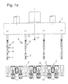
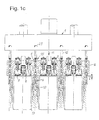
- FIG. 1a - 1d is a side view of the assembly of a Cylinder head on a crankcase in different Procedural steps shown; Fig. Le shows a top view on the fully assembled cylinder head.
- the studs 15 trained connecting elements 4 of the Assembly tools 12 of an assembly machine 1 added and in threaded bores 9 of a first component 2 - the Cylinder head 16 - screwed in the direction of arrow 13, the surface 7 (cylinder head base with the individual Combustion chamber sections) of the cylinder head 16 Assembly machines facing.
- the stud bolts 15 have two threaded sections 5, 6 which are attached opposite axial end areas of the studs extend. The two threaded sections 5, 6 are separated by a thread-free screw shaft 14.
- the stud screws 15 are inserted into the threaded holes 9 of the cylinder head 16 screwed in the first threaded section 5 of the studs in the Thread of the threaded holes 9 engages.
- the stud bolts 15 are so far in the pre-assembly according to FIG Cylinder head 16 screwed in that the studs over the surface 18 (control side) of the other side of the Protrude cylinder head 16.
- the stud bolts 15 are thereby held captively on the cylinder head 16; to Pre-assembly can be completed in FIGS. 1b-1d Final assembly shown.
- the automatic assembly machine 1 engages the opposite one Side on the studs 15 after the Cylinder head 16 together with the stud bolts 15 by 180 ° rotated and brought into the position suitable for final assembly has been in which now the surface 18 of the Cylinder head 16 is facing the automatic assembly machine.
- the Studs 15 are for this on both sides with Provided screw heads 19, 20 into which the assembly tools 12 of the assembly machine 1 can intervene and which is a directional thread start in terms of the screw heads is possible. It can therefore, without the Change position of the assembly machine, a change of Direction of screwing of arrow direction 13 during Pre-assembly according to FIG. 1a to direction of arrow 11 according to FIG.
- the threaded holes 10 which are designed as blind holes, are only included in their section adjacent to the drilling base provided with a thread so that the second threaded section 6 of the stud bolts 15 far into the threaded bores 10 protrudes until the respective threads begin to grip.
- the engaging in the screw heads of the studs 15 Start assembly tools 12 of assembly machine 1 now to rotate in the direction of rotation 23 so that the second Threaded section 6 of the studs 15 in the thread of Threaded bores 10 of the crankcase 17 is screwed.
- the differential thread of the studs 15 causes the cylinder head 16 approaches the crankcase 17.
- the Threaded bore 10 and the corresponding second Threaded section 6 of the stud 15 are with a coarser thread with a larger pitch than the first threaded portion 5 of the stud 15 or that corresponding thread of the threaded bore 9 in the cylinder head 16.
- the approximation of the two components which is expedient to Contact of the facing surfaces takes place in the first assembly step as advance with the help of angle-controlled tightening process causes.
- the Assembly tools 12 are here a certain, in advance twisted angular dimension to be set. Because there are none the tightening torque must be permanently monitored, can advance in the first assembly step with high Angle of rotation speed take place.
- the Stud bolts 15 until a predetermined one is reached Torque end value screwed in by assembly tool 1.
- the second assembly step can be done with the same assembly tools 12 or after changing the assembly tool with another, with torque monitoring equipped device are attracted. Also when changing, the assembly tools can be used without any problems inserted into the screw heads of the stud screws 15 because the angular position of the screw heads Completion of the first assembly step is known and is all screw heads expediently in the same angular position are located. Starting from this angular position, everyone will now Set screw 15 until the final torque value is reached screwed in, after the completion of the Each stud screw in a different one Angular position can be. The specification of a final torque value ensures that the studs are not beyond a permissible dimension into the crankcase be screwed in.
- FIG. Le The top view of FIG. Le shows that several Studs 15 in the plane of the surface 18 of the cylinder head 16 in front and in a row, especially around the extent of the combustion chamber areas covering the cylinders of the cylinder head are arranged.
- the stud bolts 15 point in the representation according to FIG. 1e all the same Angular orientation on; such an angular orientation is reached after completing the first assembly step.
- the same angular orientation of all stud bolts makes it easier the simultaneous intervention of the assembly tool and tightening all stud bolts at the same time.
- FIGS. 2a to 2c each show a stud 15 in different versions.
- the stud bolts 15 are each shown in side view and top view.
- Fig. 2a it is provided that the first threaded section 5 the stud 15 a larger diameter dl as the second threaded section 6 with diameter d2 having.
- the two threaded sections 5, 6 with the same direction Incline are thanks to the thread-free screw shaft 14 separated from each other, the one slightly smaller diameter than the second threaded section 6 having.
- the different assembly steps take place in Direction of arrows 25, 26, the pre-assembly - pre-assembly the stud screw on the first component - according to the Arrow direction 25 is in the same direction as that Final assembly - angle controlled advance and torque-controlled tightening - in the direction of arrow 26.
- the stud 25 is first with the second section 6 with a smaller diameter as far through a continuous threaded hole in the first component inserted until the first threaded section 5 in the Thread of the first component engages. Then follows the final assembly in the same assembly direction, whereby the second threaded section 6, which is a thread with a larger Inclination than the first threaded section 5, in the corresponding thread of the second component engages. There pre-assembly and final assembly in the same direction done, it is sufficient just a screw head 19 to provide on the stud 15, which in the area of End face adjacent to the first threaded section 5 is arranged.
- the marked points 5a, 6a each indicate the start of the thread each threaded section 5, 6; corresponding points 5b, 6b denote the end of each threaded section.
- the top view of FIG. 2a can be seen that the screw head 19 is symmetrical about this longitudinal plane 27 is trained. The alignment of the thread starts or the thread ends and the screw head in one common direction allows an exact and up front decisive intervention of the threads in the corresponding Bores of the respective components.
- Fig. 2b it is provided that the two threaded sections 5 and 6 of the stud 15 the same diameter exhibit.
- Such a threaded screw with threaded sections same diameter is in the previous described method using the example of Fig. La to le been used.
- the first threaded section 5 is initially pre-assembled in the direction of arrow 25 on the first component and then for final assembly in the opposite Screwed in the direction of arrow 26.
- the opposite Installation directions of the individual installation steps Screw heads 19, 20 on opposite axial End faces of the stud screw 15. Both screw heads 19, 20 are designed as outer edge key approaches.
- the Thread starts or ends of both thread sections are again in a common longitudinal plane 27 of the Stud 15, the thread starts 5a, 6a both Thread sections and the thread ends 5b, 6b, on different Sides of the stud 15.
- the screw head is with its narrow side at a 90 ° angle Longitudinal plane 27 aligned.
- the second threaded section 6 a larger diameter d2 than the first threaded section 5 with diameter dl.
- the mounting direction is as in the example shown in FIG. 2b for pre-assembly first in the direction of arrow 25, which Assembly tool in the opposite screw head 20 intervenes. After completion of the pre-assembly, the Final assembly in the opposite direction according to arrow 26; the assembly tool now engages the screw head 19, which is adjacent to the first threaded section 5.
- the first screw head 19 is as an outer key approach formed
- the second screw head 20 is as Formed internal socket.
- the Inner key approach that is complementary shaped Allen key to use, stands out through a space-saving design.
- All thread starts or thread ends are in common Longitudinal plane 27, the start and end of the thread 5a, 5b of the first section 5 together on one side the stud are arranged and the thread start and the thread end 6a, 6b of the second threaded section 6 the diametrically opposite side of the stud 15 are arranged.
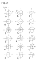
- Fig. 3 are different versions of the screw heads 19 and 20 respectively. All versions have in common that the key approach of the respective screw head too a maximum of one longitudinal plane of the stud screw symmetrical is trained. This can be advantageous aligned thread start of the thread sections opposite the key approach can be achieved. Some versions are also completely asymmetrical. It is this allows the current angular position of the Determine stud screw. All screw heads can be used as Internal or external key attachments his.
- the screw head for Longitudinal plane 27 of the stud is symmetrical.
- the Screw head has two diametrically opposite Partially circular sections with different sizes Radius, with the larger radius section above tapered flanks with the section with a smaller one Radius is connected.
- the external shape of the screw head according to FIG. 3b corresponds that of Fig. 3a; in addition there is a groove 27 provided that extends along the longitudinal plane 27.
- the screw head according to Fig. 3c which also with respect a longitudinal plane is symmetrical, has two Partially circular sections with different radius on, with the transition between the two sections is also realized via flanks which are partly circular.
- the screw head according to FIG. 3d detects eight radially externally directed tines that are even across the circumference are distributed. It is a groove-shaped Incision is provided, which extends in the plane of symmetry and a little longer than the radius of the screw head is.
- the screw head according to 3e consists of five straight flanks arranged at an angle to one another, two adjacent ones Flanks over a part-circular section are connected.
- the screw head according to FIG. 3f which with respect to a Longitudinal plane is symmetrical, has a part-circular Section at which two straight lines diverging Extend flanks.
- the flanks are on the part-circular Section facing away from you by a rounded Section connected to one another has semicircular recess.
- the screw head according to FIG. 3g is more conventional Hexagon screw head executed, being an eccentric Recess with two semicircular sections is provided.
- FIG. 3h is a similar design like that of Fig. 3g, wherein the recess one has circular cross section.
- the screw head according to FIG. 3i is like that from FIG. 3d provided with teeth pointing radially outwards, whereby on opposite sides of the plane of symmetry a prong is missing.
- the defects are arranged so that four prongs on one side of the screw head and on the other opposite side of the screw head two prongs are arranged.
- the screw head according to Fig. 3j has a circular Cross-section, with two perpendicular to each other Grooves are provided and one of these grooves outside of one Longitudinal plane of the screw pin lies.
- the screw head according to FIG. 3k also has one circular cross section; continue to be two eccentric, circular recesses with different radius intended.
- the screw head according to Fig. 3l also has one circular cross section; it is a groove-shaped recess provided approximately the cross-sectional shape of the number "7", the long leg of the groove The outer contour of the screw head breaks through.
- the screw head 3l has a completely asymmetrical Cross section on.
- the screw head according to Fig. 3m has a square Cross-section, one flank of the square being a semicircular Has recess.
- 3n has a circular cross-section with an internal, irregular recess, which gives the screw head an asymmetrical cross-sectional shape Has.
- the screw head according to FIG. 3o is like that of FIG. 3d, 3i provided with teeth pointing radially outwards, one prong is missing and one instead of the prong triangular recess is attached.
- the screw head according to FIG. 3p is pentagonal; it is still outside the plane of symmetry horizontal, continuous groove provided.
- 3q has a circular head Cross-sectional shape; on diametrically opposite sides are two part-circular recesses with different large radius provided.
- 3r has a trapezoidal shape Cross-section.
- the different screw head shapes enable one Clear identification of the angular position of the stud bolts.
- the asymmetrical shape or only with respect to one Longitudinal plane represents the symmetrical shape of the screw heads insofar as a marking for the respective angular position of the Set screw, or it can be a unique Alignment of the thread start of the thread sections to the Screw heads can be achieved.
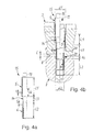
- 4a, 4b is an example of an expedient Dimensioning of a stud screw at given Proportions of the threaded holes in the two to be screwed Components shown.
- the stud 15 is in the threaded holes 9, 10 of the Components 2 and 3 screwed in.
- the stud 15 has two threaded sections 5, 6 with different Diameter d1, d2, the first threaded section 5 a smaller pitch s than the second threaded section 6 has a larger slope S, see Fig. 4a.
- the Thread section 5 has the length l1, the thread section 6 the length l2.
- the two threaded sections are through the thread-free screw shaft 14 with length l3 separated.
- the first threaded section 5 is adjacent Screw head 19 is provided.
- Fig. 4b shows the stud 15 in two different Positions screwed into components 2, 3.
- the stud 15 In the left part of Fig. 4b is the stud 15 only with the thread of the first threaded bore 9 of the component 2 screwed while the second threaded portion 6 of Set screw 15 straight on the thread of the second threaded hole 10 of component 3 begins to intervene; the mutually facing surfaces 7 and 8 of components 2 and 3 have the distance l to each other.
- the distance l is chosen so that due to the difference in thread pitches S and s of the threaded sections 6 and 5 the distance l after n turns of the stud 15 becomes; the distance l is therefore calculated from the Difference in thread pitches multiplied by the number n revolutions.
- the threaded hole 9 in component 2 which has the length Ll, includes itself in the direction of the second component 3 thread-free section 28 of length tl.
- the recess in component 3 is also wise executed.
- the component 2 faces a thread-free one Section 29 of length t2 provided to the the threaded bore 10 of length L2 joins.
- the Recess in component 2 is a through hole that Recess in component 3 as a blind hole.
- the length l1 of the first threaded section 5 of the Stud 15 by a certain amount ⁇ l compared to Length L1 of the receiving thread 9 of the component 2 to be enlarged.
- the length l3 of the unthreaded Screw shaft 14 corresponds to the stud 15 the length tl and t2 of the two thread-free sections 28, 29 in components 2 and 3, reduced by the dimension ⁇ l.
- the length of the first threaded section 5 and the screw shaft 14 of the stud 15 approximately the same length as the length of the threaded hole 9 in component 2 including the two unthreaded sections 28, 29, only the length ratios of the threaded section are moved to the thread-free section.
- the length l2 of the second threaded portion 6 is no longer than the receiving thread 10 of the second component 3, which has the length L2.
- FIG. 5a to 5d is a further embodiment based on the installation of a crankshaft bearing cap on Crankcase shown.
- 5a two are parallel Studs 15 from the assembly machine 1 over the Assembly tools 12 in threaded holes Crankshaft bearing cover 30 and a crankcase 17th screwed in.
- Fig. 5a shows the device at the beginning of angle-controlled advance; in this position gapes between the crankcase 17 and the crankshaft bearing cap 30 a gap of width 1.
- Fig. 5b a stud 15 with two threaded sections, 5, 6 different diameters (Section 5 has the larger diameter) which is suitable for pre-assembly and final assembly in the same assembly direction perform.
- the screw head 19 is as Inner key approach executed.
- FIG. 5c and 5d show a plan view of the crankshaft bearing cover 30 in different stages of the tightening process.
- the studs are at the beginning of the Assembly process or after completion of the angle-controlled Shown advance; the screw heads 19 the studs are aligned in the same direction.
- Fig. 5d shows the studs at the end of the Assembly process. After tightening with torque control point the studs after reaching a common one specified final torque value an individual Angular position. The different angular position can also come about by the fact that each stud screw with an individual tightening torque is tightened.
- 6a, 6b is the mounting of a bearing cover 31 shown on a connecting rod 32.
- the threaded sections of the Stud 15 have a different one Diameter on and the screw head 19 is as a socket wrench educated.
- the stud bolts 15 are completely sunk into the components 31, 32, whereby the installation space is reduced. Because of the same Differential thread can be set screws 15 with a low tightening torque, but still a high screw force acts between the components. It is also conceivable to use stud bolts 15 with the same Diameters to be used on the thread sections.
- the Bearing cover 31 is broken or cracked Pull separate from the connecting rod. The threaded holes in the connecting rod before cracking (cracking) manufactured.
- the threaded portion is with the larger diameter and the smaller thread pitch intended.
- the threaded section with the smaller one Diameter and the larger thread pitch in the connecting rod, with both threaded sections through a threadless bore section are separated, in whose level is also the fracture level between the connecting rod and Bearing cover is placed.
- the pre-assembled state of Bearing cover 31 and connecting rod 32 is through the Studs 15 always acting in every direction Form fit and in the permanently installed state also in positive locking and non-positive locking in every direction reached.
- the pre-assembled components 31 and 32 move in the final assembly towards each other, the Fractures on the connecting rod and the bearing cover itself touch first before bracing against each other become.
- Such a screwed bearing cap 31 requires no further securing elements against longitudinal and Transverse thrust or rotation of the components to one another.
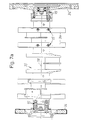
- crankshafts 7a, 7b show a crankshaft with an assembled one Flywheel and several counterweights.
- the counterweights 34 are by means of the studs 15 with the Screwed crankshaft 33, the stud bolts approximately aligned radially in the direction of the longitudinal axis 38 of the crankshaft are.
- crankshaft end Flywheel 35 is provided, also via stud bolts 15 is screwed to the crankshaft 33.
- the Stud bolts 15 of the flywheel 35 are axially parallel to the longitudinal axis 38 of the crankshaft 33.
- On the Flywheel 35 opposite side of crankshaft 33 a further counterweight 36 is provided, which likewise by means of stud bolts 15 on the crankshaft is attached.
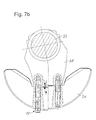
- FIG. 7b shows a section through the crankshaft 33 with a view of a counterweight 34.
- the counterweight 34 In the left Part of FIG. 7b is the counterweight 34 at the beginning the assembly process shown; the counterweight 34 lies still at a distance l from a cam 37 of the crankshaft 33, to which the counterweight is attached.
- the counterweight 34 In the right Part of FIG. 7b, the counterweight 34 is fixed on Cam 37 tightened.
- Tapping is done with a tapping tool 39, which two in the region of an axial end has cutting heads 40, 41 arranged one behind the other, the first cutting head 40 having a larger diameter has as the second cutting head 41, which extends up to extends axially end face of the cutting tool 39.
- the two cutting heads 40, 41 produce threads with different Gradients, where appropriate the first Cutting head 40 with a larger diameter a thread smaller Slope generated as the second cutting head 41.
- Die two threaded holes 9, 10 are advantageous in one Operation generated in the direction of arrow 42, initially the thread of the threaded hole 9 in component 2 is cut by the threaded head 40 and then the thread of the threaded bore 10 of the second component 3 is cut by the cutting head 41.
- On the thread of the Threaded bore 9 closes a thread-free section whose diameter is such that the first Cutting head 40 can be passed without hindrance can.
- the feed of the cutting tool 39 is advantageous depending on the speed of rotation and the selected thread pitch.
- the cutting tool 39 has one Threaded rod 43 with a first cutting head 40 smaller Diameter.
- the threaded rod 43 is in the axial direction to move relative to a threaded sleeve 44 whose External thread as a cutting head 41 with a larger diameter is trained.
- the cutting head 40 on the threaded rod 43 is conveniently suitable for a thread with a larger To cut slope than the cutting head 41 on the Threaded sleeve 44.
- On the respective cutting heads facing away from both the threaded rod 43 as also the threaded sleeve 44 engages 45 with which the respective components can be axially secured.
- FIG. 8e shows that both the Threaded rod 43 and the encompassing threaded sleeve 44 have a characteristic screw head, which clearly shows in which current one Angular position of the threaded rod and the threaded sleeve are located.
- FIG 8f shows a drilling device 46 with receiving units 47 is provided, in which the tapping tools can be used.
- the drilling device 46 has a feed control that is dependent on the pitch of the thread to be cut can be.
- the automatic assembly machine can be used as the drilling device 46 be used.
- the connecting element 4 is in the Version shown as a union nut 48.
- a union nut 48 For better Comprehensibility are the same components as in the previous ones described examples with the same reference numerals Mistake.
- the union nut 48 has two threaded sections 5, 6 on, each as an internal thread 60, 61 of the approximately cylindrical Union nut are executed.
- the threaded sections 5, 6 are aligned and have a different Thread.
- the second thread section 6 with a larger slope also has a larger one Diameter on.
- the outer jacket of the union nut 48 is Appropriately provided with a key contour so that the Union nut from a suitably shaped tool can be tightened and released.
- Between the two Threaded sections 5, 6 is a thread-free inner section 14 provided.
- the first and the second thread section 5 and 6 each extend approximately over almost half the length of the union nut and are of that thread-free inner section of short length separated.
- the union nut 48 is provided for two threaded members 49, 50 to connect with the threaded sections 5, 6 provided threads corresponding to the union nut are.
- the threaded members 49, 50 are as threaded bolts or Threaded connector executed and are parts of components 2, 3rd
- Fig. 9c represents the beginning of the final assembly in which the tapered face of the first threaded member 49 with an axial distance 1 to the funnel-shaped recess of the second threaded member 50.
- the distance l advantageously corresponds to the difference in the thread pitches the threaded sections 6 and 5 of the union nut 48, multiplied by the number of revolutions n that the Execute union nut 48 to overcome distance 1 got to.
- FIG. 9d shows the device in the fully assembled state, in which the threaded members 49, 50 are firmly connected.
- the threaded members 49, 50 can be designed as lines be and have an inner channel 54, 55.
- the conical Formation of the end face of the threaded member 49 and the Complementally shaped recess in the threaded member 50 ensure a tight connection.
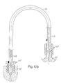
- 10a, 10b show the prescribed method using a union nut using the example of a Injection line.
- Component 2 is an injection line 56 executed at their respective axial end regions is provided with threaded members 49.
- the two threaded links 49 are supposed to 48 with the help of union nuts Threaded connector 50 of a component 3 are screwed on.
- the injection line 56 describes an arc so that the threaded members 49 arranged in the end region are angular cross, especially at an angle of about 90 °.
- To The beginning of the screwing process is the axial one End face of each threaded member 49 at a distance of 1 to receiving funnel-shaped recess in each Threaded connector 50.
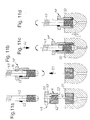
- Fig. Lla to lld show the screwing of two Components with a union nut 48 in another Execution.
- the union nut 48 has a first threaded section 5 with a small slope, which is on the inside of the union nut about half the length the union nut extends.
- the second threaded section 6 is on the outside 57 of the union nut with a larger one Diameter arranged; the threaded section 6 has one greater pitch than that designed as an internal thread 60 first threaded section 5, it is slightly longer than that half length of the union nut 48 is formed. Both Thread section extend to the same Face 59 of the union nut.
- a nut head 58 is provided, the diameter of which is advantageously larger than the diameter of the External thread 62.
- the nut head 58 expediently has one Contour on the problem-free attachment of an assembly tool allowed and also the current angular position the union nut.
- On the outside is 57 between the nut head 58 and the external thread 62 short thread-free section provided.
- the external thread 62 of the union nut is in the threaded member Screw 50, which has a threaded bore.
- the internal thread 60 of the union nut is with the Threaded member 49 screwed.
- the injection line 56 is approximately U-shaped formed and has at both axial end regions one threaded member 49 each.
- On each threaded link 49 is a union nut 48 pre-assembled, in the left Half of the picture of FIGS. 12a, 12b with the union nut 48 is provided with an internal thread and an external thread and the union nut according to the right half of the picture two Has internal thread.
- the tightening process takes place for both Union nuts in the direction of arrow 52, the Union nuts first on the thread of the second Threaded member 50 are attached.
- the tapered The end face of each threaded member 49 lies at an axial distance 1 to the funnel-shaped recess in the second threaded member 50.
Landscapes
- Engineering & Computer Science (AREA)
- Mechanical Engineering (AREA)
- General Engineering & Computer Science (AREA)
- Shafts, Cranks, Connecting Bars, And Related Bearings (AREA)
- Details Of Spanners, Wrenches, And Screw Drivers And Accessories (AREA)
- Fuel-Injection Apparatus (AREA)
- Connection Of Plates (AREA)
- Joints With Pressure Members (AREA)
Applications Claiming Priority (3)
| Application Number | Priority Date | Filing Date | Title |
|---|---|---|---|
| DE19545610 | 1995-12-07 | ||
| DE19545610A DE19545610C2 (de) | 1995-12-07 | 1995-12-07 | Verfahren für das automatische Verschrauben von zwei Bauteilen und Stiftschraube und Überwurfmutter zur Durchführung des Verfahrens |
| EP96937232A EP0868254B1 (fr) | 1995-12-07 | 1996-10-25 | Procede d'assemblage par vissage automatique de deux composants et goujon et ecrou d'accouplement utilises a cet effet |
Related Parent Applications (1)
| Application Number | Title | Priority Date | Filing Date |
|---|---|---|---|
| EP96937232A Division EP0868254B1 (fr) | 1995-12-07 | 1996-10-25 | Procede d'assemblage par vissage automatique de deux composants et goujon et ecrou d'accouplement utilises a cet effet |
Publications (3)
| Publication Number | Publication Date |
|---|---|
| EP0972607A2 true EP0972607A2 (fr) | 2000-01-19 |
| EP0972607A3 EP0972607A3 (fr) | 2000-03-01 |
| EP0972607B1 EP0972607B1 (fr) | 2005-06-15 |
Family
ID=7779410
Family Applications (2)
| Application Number | Title | Priority Date | Filing Date |
|---|---|---|---|
| EP96937232A Expired - Lifetime EP0868254B1 (fr) | 1995-12-07 | 1996-10-25 | Procede d'assemblage par vissage automatique de deux composants et goujon et ecrou d'accouplement utilises a cet effet |
| EP99119265A Expired - Lifetime EP0972607B1 (fr) | 1995-12-07 | 1996-10-25 | Agencement de connexion |
Family Applications Before (1)
| Application Number | Title | Priority Date | Filing Date |
|---|---|---|---|
| EP96937232A Expired - Lifetime EP0868254B1 (fr) | 1995-12-07 | 1996-10-25 | Procede d'assemblage par vissage automatique de deux composants et goujon et ecrou d'accouplement utilises a cet effet |
Country Status (6)
| Country | Link |
|---|---|
| US (1) | US6233807B1 (fr) |
| EP (2) | EP0868254B1 (fr) |
| JP (1) | JPH11514591A (fr) |
| KR (1) | KR19990071983A (fr) |
| DE (1) | DE19545610C2 (fr) |
| WO (1) | WO1997020656A1 (fr) |
Cited By (1)
| Publication number | Priority date | Publication date | Assignee | Title |
|---|---|---|---|---|
| DE102007002824A1 (de) * | 2007-01-19 | 2008-04-03 | Audi Ag | Verfahren zum Verschrauben zweier Bauteile |
Families Citing this family (22)
| Publication number | Priority date | Publication date | Assignee | Title |
|---|---|---|---|---|
| ITMI981644A1 (it) * | 1998-07-17 | 2000-01-17 | Urama S R L | Perfezionamenti alle ghiere metalliche autofrenanti e procedimenti per la loro produzione |
| US6385837B1 (en) | 1999-04-05 | 2002-05-14 | Central Motor Wheel Co., Ltd. | Method and apparatus for fixedly connecting threaded tubes, and recording medium storing control program for practicing or controlling those method and apparatus |
| US6560867B2 (en) * | 2001-07-10 | 2003-05-13 | Eaton Corporation | Modular valvetrain and cylinder head structure |
| US20060090325A1 (en) * | 2004-11-02 | 2006-05-04 | Bernard Jeremy R | Vehicle powertrain joints comprising self-tapping fasteners |
| US20060104742A1 (en) * | 2004-11-12 | 2006-05-18 | Fleming David T | Stud for parts assembly |
| US20070018132A1 (en) * | 2005-07-22 | 2007-01-25 | Gethmann Douglas P | Multi-pitch threaded coupling |
| DE102008036419A1 (de) * | 2008-08-05 | 2010-02-18 | Continental Automotive Gmbh | Verfahren und Vorrichtung zum Einstellen und Festlegen einer Schraubverbindung |
| JP5195154B2 (ja) * | 2008-08-21 | 2013-05-08 | マツダ株式会社 | ボルト締結方法及びその装置 |
| DE102010054089B3 (de) * | 2010-12-10 | 2012-05-24 | Audi Ag | Schraubvorrichtung, insbesondere für Montagelinien zur Fahrzeugmontage |
| CN102720502B (zh) * | 2012-06-18 | 2014-08-06 | 中煤第三建设(集团)有限责任公司 | 立井砌筑模板组装风动快速装拆器 |
| EP2935856B1 (fr) * | 2012-12-20 | 2016-11-02 | Volvo Truck Corporation | Agencement d'alimentation en combustible d'un moteur |
| DE102013202191A1 (de) | 2013-02-11 | 2014-08-14 | Continental Automotive Gmbh | Abgasturbolader mit einer Regeleinheit |
| DE102013006889A1 (de) | 2013-04-20 | 2014-10-23 | Daimler Ag | Befestigungsanordnug von Lagerelementen an einem Kurbelgehäuse für eine Hubkolben-Verbrennungskraftmaschine sowie Verfahren zum Herstellen einer solchen Befestigungsanordnung |
| DE102013009756A1 (de) | 2013-06-11 | 2014-12-11 | Daimler Ag | Befestigungsanordnung von Lagerelementen an einem Kurbelgehäuse für eine Hubkolben-Verbrennungskraftmaschine |
| CN103286555B (zh) * | 2013-06-13 | 2015-05-27 | 无锡威孚汽车柴油系统有限公司 | 喷油器总成的拧紧方法 |
| DE102013114318B4 (de) * | 2013-12-18 | 2016-09-22 | Steyr Motors Gmbh | Mehrteiliges Kurbelgehäuse und Montageverfahren |
| CN105127712A (zh) * | 2015-10-06 | 2015-12-09 | 周家全 | 一种发动机空压机三角形定位工装及其工艺方法 |
| US10433639B2 (en) * | 2016-01-20 | 2019-10-08 | The Music People, Inc. | Connection adapter for music stand |
| WO2021042221A1 (fr) * | 2019-09-03 | 2021-03-11 | Mi Robotic Solutions S.A. | Dispositif ou outil automatique pour l'extraction et l'installation de moyens de fixation des revêtements dans un moulin; procédé d'installation des moyens de fixation d'un revêtement; procédé d'élimination des moyens de fixation d'un revêtement |
| CN112922946A (zh) * | 2021-01-18 | 2021-06-08 | 紧固仓盟(江苏)科技有限公司 | 一种具有双向调节机构的分体式螺纹紧固件 |
| CN113211348B (zh) * | 2021-05-12 | 2023-03-14 | 四川亚美动力技术有限公司 | 一种用于螺钉组件精确定位的装置 |
| CN115365786B (zh) * | 2022-09-28 | 2024-10-15 | 北京中车重工机械有限公司 | 一种自动装配工作站及其装配方法 |
Family Cites Families (15)
| Publication number | Priority date | Publication date | Assignee | Title |
|---|---|---|---|---|
| US3046953A (en) * | 1960-05-03 | 1962-07-31 | Dolza John | Internal combustion engines |
| FR2317999A1 (fr) * | 1975-07-15 | 1977-02-11 | Peugeot | Machine, notamment pour le serrage de vis |
| JPS5544029A (en) * | 1978-09-21 | 1980-03-28 | Nissan Motor Co Ltd | Working valve gear of power steering gear |
| DE3216773A1 (de) * | 1982-05-05 | 1983-11-10 | Dr. Staiger, Mohilo + Co GmbH, 7060 Schorndorf | Vorrichtung zum anziehen eines ein gewinde tragenden verbindungselements mit begrenzung des endanzugsdrehmoments |
| JPS6119527A (ja) * | 1984-07-04 | 1986-01-28 | Nissan Motor Co Ltd | シリンダヘツドのボルト締付方法 |
| DE3519352A1 (de) * | 1985-05-30 | 1986-12-04 | Robert Bosch Gmbh, 7000 Stuttgart | Schraubvorrichtung mit motorgetriebenem schraubendreher |
| US4745892A (en) * | 1985-06-28 | 1988-05-24 | Audi Ag | Internal combustion engine |
| US4784554A (en) * | 1985-09-26 | 1988-11-15 | Break Douglas G | T-bolt assembly |
| JPS62101879A (ja) * | 1985-10-29 | 1987-05-12 | Sanshin Ind Co Ltd | 燃料噴射エンジンにおける燃料供給配管の接続構造 |
| US4887341A (en) * | 1986-09-01 | 1989-12-19 | Mazda Motor Corporation | Method and apparatus for fitting component sections |
| JP2511094B2 (ja) * | 1988-02-04 | 1996-06-26 | 株式会社日立製作所 | 回転角制御によるねじ締付け装置 |
| JP2690577B2 (ja) * | 1989-12-19 | 1997-12-10 | マツダ株式会社 | ねじの締付方法 |
| JP3040827B2 (ja) * | 1990-12-14 | 2000-05-15 | 日本パワーファスニング株式会社 | 締結装置 |
| DE4126539A1 (de) * | 1991-08-10 | 1993-02-11 | Dieter Ammer | Set aus schraube und werkzeug |
| US5248232A (en) * | 1992-02-10 | 1993-09-28 | Chiang Chih Chung | Fixing means |
-
1995
- 1995-12-07 DE DE19545610A patent/DE19545610C2/de not_active Expired - Fee Related
-
1996
- 1996-10-25 EP EP96937232A patent/EP0868254B1/fr not_active Expired - Lifetime
- 1996-10-25 EP EP99119265A patent/EP0972607B1/fr not_active Expired - Lifetime
- 1996-10-25 KR KR1019980704274A patent/KR19990071983A/ko not_active Ceased
- 1996-10-25 WO PCT/EP1996/004641 patent/WO1997020656A1/fr not_active Ceased
- 1996-10-25 JP JP9520896A patent/JPH11514591A/ja not_active Ceased
-
1998
- 1998-06-08 US US09/092,976 patent/US6233807B1/en not_active Expired - Fee Related
Cited By (1)
| Publication number | Priority date | Publication date | Assignee | Title |
|---|---|---|---|---|
| DE102007002824A1 (de) * | 2007-01-19 | 2008-04-03 | Audi Ag | Verfahren zum Verschrauben zweier Bauteile |
Also Published As
| Publication number | Publication date |
|---|---|
| WO1997020656A1 (fr) | 1997-06-12 |
| US6233807B1 (en) | 2001-05-22 |
| DE19545610A1 (de) | 1997-06-12 |
| EP0972607B1 (fr) | 2005-06-15 |
| EP0972607A3 (fr) | 2000-03-01 |
| EP0868254A1 (fr) | 1998-10-07 |
| EP0868254B1 (fr) | 2001-06-13 |
| DE19545610C2 (de) | 1998-02-19 |
| KR19990071983A (ko) | 1999-09-27 |
| JPH11514591A (ja) | 1999-12-14 |
Similar Documents
| Publication | Publication Date | Title |
|---|---|---|
| EP0972607B1 (fr) | Agencement de connexion | |
| DE19902461B4 (de) | Mutter mit T-förmigem Querschnitt | |
| EP2163773B1 (fr) | Vis à centrage automatique | |
| EP1409185B2 (fr) | Outil de formage de filet ou taraud | |
| EP3176445A1 (fr) | Dispositif destiné à appliquer un premier composant sur un second composant | |
| DE3831397C2 (de) | Kombination eines Schneidwerkzeugs mit einer Befestigungseinheit zum Befestigen des Schneidwerkzeugs | |
| EP2405150B1 (fr) | Elément à blindage fileté, vis dotée d'un élément à blindage fileté, procédé d'installation pour celui-ci et composant doté d'un élément à blindage fileté installé | |
| DE3102939A1 (de) | "einpressmutter" | |
| EP2224143B1 (fr) | Ecrou, raccordement de vis, connexion de profilé, ainsi que procédé de fabrication d'un écrou | |
| DE69501636T2 (de) | Einsatzmutter und Befestigungselement | |
| EP3156666A1 (fr) | Systeme de fixation d'un element de machine | |
| EP3374649B1 (fr) | Vis autotaraudeuse | |
| DE102013110189B4 (de) | Einstellvorrichtung | |
| DE10020218B4 (de) | Montageeinheit aus einem Bauteil und mindestens einer gewindeformenden Schraube | |
| WO2005017372A1 (fr) | Dispositif comportant deux profiles creux assembles par une vis et outil correspondant | |
| DE19912068B4 (de) | Wellen- oder Stellmutter und Verfahren zu ihrer Herstellung | |
| EP0591507A1 (fr) | Element d'assemblage par serrage du type rivet borgne | |
| DE69302482T2 (de) | Rohrverbinder | |
| WO2007048467A1 (fr) | Porte-outil | |
| EP4090854B1 (fr) | Manchon de contre-palier | |
| DE3245896A1 (de) | Wellenausdreher | |
| WO2014016020A1 (fr) | Élément à filetage extérieur, assemblage par complémentarité de forme et moteur à combustion interne | |
| AT522190B1 (de) | Lagerdeckel | |
| DE10304182B4 (de) | Gewindeformer oder -bohrer | |
| DE19611806C2 (de) | Verbindungsbolzen |
Legal Events
| Date | Code | Title | Description |
|---|---|---|---|
| PUAI | Public reference made under article 153(3) epc to a published international application that has entered the european phase |
Free format text: ORIGINAL CODE: 0009012 |
|
| PUAL | Search report despatched |
Free format text: ORIGINAL CODE: 0009013 |
|
| AC | Divisional application: reference to earlier application |
Ref document number: 868254 Country of ref document: EP |
|
| AK | Designated contracting states |
Kind code of ref document: A2 Designated state(s): FR GB IT SE |
|
| AK | Designated contracting states |
Kind code of ref document: A3 Designated state(s): FR GB IT SE |
|
| RIC1 | Information provided on ipc code assigned before grant |
Free format text: 7B 23P 19/06 A, 7F 16B 7/18 B, 7F 16B 37/14 B, 7F 02M 55/02 B |
|
| 17P | Request for examination filed |
Effective date: 20000202 |
|
| AKX | Designation fees paid |
Free format text: FR GB IT SE |
|
| 17Q | First examination report despatched |
Effective date: 20030328 |
|
| GRAP | Despatch of communication of intention to grant a patent |
Free format text: ORIGINAL CODE: EPIDOSNIGR1 |
|
| GRAS | Grant fee paid |
Free format text: ORIGINAL CODE: EPIDOSNIGR3 |
|
| GRAA | (expected) grant |
Free format text: ORIGINAL CODE: 0009210 |
|
| AC | Divisional application: reference to earlier application |
Ref document number: 0868254 Country of ref document: EP Kind code of ref document: P |
|
| AK | Designated contracting states |
Kind code of ref document: B1 Designated state(s): FR GB IT SE |
|
| REG | Reference to a national code |
Ref country code: GB Ref legal event code: FG4D Free format text: NOT ENGLISH |
|
| REG | Reference to a national code |
Ref country code: SE Ref legal event code: TRGR |
|
| GBT | Gb: translation of ep patent filed (gb section 77(6)(a)/1977) |
Effective date: 20050721 |
|
| PGFP | Annual fee paid to national office [announced via postgrant information from national office to epo] |
Ref country code: SE Payment date: 20051013 Year of fee payment: 10 |
|
| PGFP | Annual fee paid to national office [announced via postgrant information from national office to epo] |
Ref country code: FR Payment date: 20051014 Year of fee payment: 10 |
|
| PGFP | Annual fee paid to national office [announced via postgrant information from national office to epo] |
Ref country code: GB Payment date: 20051017 Year of fee payment: 10 |
|
| ET | Fr: translation filed | ||
| PLBE | No opposition filed within time limit |
Free format text: ORIGINAL CODE: 0009261 |
|
| STAA | Information on the status of an ep patent application or granted ep patent |
Free format text: STATUS: NO OPPOSITION FILED WITHIN TIME LIMIT |
|
| 26N | No opposition filed |
Effective date: 20060316 |
|
| PG25 | Lapsed in a contracting state [announced via postgrant information from national office to epo] |
Ref country code: SE Free format text: LAPSE BECAUSE OF NON-PAYMENT OF DUE FEES Effective date: 20061026 |
|
| PGFP | Annual fee paid to national office [announced via postgrant information from national office to epo] |
Ref country code: IT Payment date: 20061031 Year of fee payment: 11 |
|
| EUG | Se: european patent has lapsed | ||
| GBPC | Gb: european patent ceased through non-payment of renewal fee |
Effective date: 20061025 |
|
| REG | Reference to a national code |
Ref country code: FR Ref legal event code: ST Effective date: 20070629 |
|
| PG25 | Lapsed in a contracting state [announced via postgrant information from national office to epo] |
Ref country code: GB Free format text: LAPSE BECAUSE OF NON-PAYMENT OF DUE FEES Effective date: 20061025 |
|
| PG25 | Lapsed in a contracting state [announced via postgrant information from national office to epo] |
Ref country code: FR Free format text: LAPSE BECAUSE OF NON-PAYMENT OF DUE FEES Effective date: 20061031 |
|
| PG25 | Lapsed in a contracting state [announced via postgrant information from national office to epo] |
Ref country code: IT Free format text: LAPSE BECAUSE OF NON-PAYMENT OF DUE FEES Effective date: 20071025 |