EP0972660A1 - Sensoranordnung an einer Radaufhängung für ein Fahrzeug - Google Patents
Sensoranordnung an einer Radaufhängung für ein Fahrzeug Download PDFInfo
- Publication number
- EP0972660A1 EP0972660A1 EP99111629A EP99111629A EP0972660A1 EP 0972660 A1 EP0972660 A1 EP 0972660A1 EP 99111629 A EP99111629 A EP 99111629A EP 99111629 A EP99111629 A EP 99111629A EP 0972660 A1 EP0972660 A1 EP 0972660A1
- Authority
- EP
- European Patent Office
- Prior art keywords
- sensor
- vehicle body
- swivel arm
- fastening element
- arrangement according
- Prior art date
- Legal status (The legal status is an assumption and is not a legal conclusion. Google has not performed a legal analysis and makes no representation as to the accuracy of the status listed.)
- Granted
Links
- 239000000725 suspension Substances 0.000 title claims description 19
- 238000004519 manufacturing process Methods 0.000 description 9
- 238000009434 installation Methods 0.000 description 6
- 230000001419 dependent effect Effects 0.000 description 2
- 230000015572 biosynthetic process Effects 0.000 description 1
- 230000008859 change Effects 0.000 description 1
- 230000008878 coupling Effects 0.000 description 1
- 238000010168 coupling process Methods 0.000 description 1
- 238000005859 coupling reaction Methods 0.000 description 1
- 230000006735 deficit Effects 0.000 description 1
- 238000001514 detection method Methods 0.000 description 1
- 230000001771 impaired effect Effects 0.000 description 1
- 238000005259 measurement Methods 0.000 description 1
- 238000000034 method Methods 0.000 description 1
- 230000004048 modification Effects 0.000 description 1
- 238000012986 modification Methods 0.000 description 1
- 230000009467 reduction Effects 0.000 description 1
- 230000001105 regulatory effect Effects 0.000 description 1
- 210000005182 tip of the tongue Anatomy 0.000 description 1
Images

Classifications
-
- B—PERFORMING OPERATIONS; TRANSPORTING
- B60—VEHICLES IN GENERAL
- B60G—VEHICLE SUSPENSION ARRANGEMENTS
- B60G17/00—Resilient suspensions having means for adjusting the spring or vibration-damper characteristics, for regulating the distance between a supporting surface and a sprung part of vehicle or for locking suspension during use to meet varying vehicular or surface conditions, e.g. due to speed or load
- B60G17/015—Resilient suspensions having means for adjusting the spring or vibration-damper characteristics, for regulating the distance between a supporting surface and a sprung part of vehicle or for locking suspension during use to meet varying vehicular or surface conditions, e.g. due to speed or load the regulating means comprising electric or electronic elements
- B60G17/019—Resilient suspensions having means for adjusting the spring or vibration-damper characteristics, for regulating the distance between a supporting surface and a sprung part of vehicle or for locking suspension during use to meet varying vehicular or surface conditions, e.g. due to speed or load the regulating means comprising electric or electronic elements characterised by the type of sensor or the arrangement thereof
- B60G17/01933—Velocity, e.g. relative velocity-displacement sensors
-
- B—PERFORMING OPERATIONS; TRANSPORTING
- B60—VEHICLES IN GENERAL
- B60G—VEHICLE SUSPENSION ARRANGEMENTS
- B60G2200/00—Indexing codes relating to suspension types
- B60G2200/10—Independent suspensions
- B60G2200/14—Independent suspensions with lateral arms
- B60G2200/142—Independent suspensions with lateral arms with a single lateral arm, e.g. MacPherson type
-
- B—PERFORMING OPERATIONS; TRANSPORTING
- B60—VEHICLES IN GENERAL
- B60G—VEHICLE SUSPENSION ARRANGEMENTS
- B60G2204/00—Indexing codes related to suspensions per se or to auxiliary parts
- B60G2204/10—Mounting of suspension elements
- B60G2204/11—Mounting of sensors thereon
-
- B—PERFORMING OPERATIONS; TRANSPORTING
- B60—VEHICLES IN GENERAL
- B60G—VEHICLE SUSPENSION ARRANGEMENTS
- B60G2204/00—Indexing codes related to suspensions per se or to auxiliary parts
- B60G2204/10—Mounting of suspension elements
- B60G2204/11—Mounting of sensors thereon
- B60G2204/116—Sensors coupled to the suspension arm
-
- B—PERFORMING OPERATIONS; TRANSPORTING
- B60—VEHICLES IN GENERAL
- B60G—VEHICLE SUSPENSION ARRANGEMENTS
- B60G2204/00—Indexing codes related to suspensions per se or to auxiliary parts
- B60G2204/10—Mounting of suspension elements
- B60G2204/14—Mounting of suspension arms
- B60G2204/143—Mounting of suspension arms on the vehicle body or chassis
-
- B—PERFORMING OPERATIONS; TRANSPORTING
- B60—VEHICLES IN GENERAL
- B60G—VEHICLE SUSPENSION ARRANGEMENTS
- B60G2204/00—Indexing codes related to suspensions per se or to auxiliary parts
- B60G2204/40—Auxiliary suspension parts; Adjustment of suspensions
- B60G2204/422—Links for mounting suspension elements
-
- B—PERFORMING OPERATIONS; TRANSPORTING
- B60—VEHICLES IN GENERAL
- B60G—VEHICLE SUSPENSION ARRANGEMENTS
- B60G2204/00—Indexing codes related to suspensions per se or to auxiliary parts
- B60G2204/40—Auxiliary suspension parts; Adjustment of suspensions
- B60G2204/43—Fittings, brackets or knuckles
-
- B—PERFORMING OPERATIONS; TRANSPORTING
- B60—VEHICLES IN GENERAL
- B60G—VEHICLE SUSPENSION ARRANGEMENTS
- B60G2400/00—Indexing codes relating to detected, measured or calculated conditions or factors
- B60G2400/05—Attitude
- B60G2400/051—Angle
- B60G2400/0516—Angular position of a suspension element
- B60G2400/05162—Angular position of a suspension element the element being a suspension arm
-
- B—PERFORMING OPERATIONS; TRANSPORTING
- B60—VEHICLES IN GENERAL
- B60G—VEHICLE SUSPENSION ARRANGEMENTS
- B60G2400/00—Indexing codes relating to detected, measured or calculated conditions or factors
- B60G2400/25—Stroke; Height; Displacement
- B60G2400/252—Stroke; Height; Displacement vertical
-
- B—PERFORMING OPERATIONS; TRANSPORTING
- B60—VEHICLES IN GENERAL
- B60G—VEHICLE SUSPENSION ARRANGEMENTS
- B60G2401/00—Indexing codes relating to the type of sensors based on the principle of their operation
-
- G—PHYSICS
- G01—MEASURING; TESTING
- G01D—MEASURING NOT SPECIALLY ADAPTED FOR A SPECIFIC VARIABLE; ARRANGEMENTS FOR MEASURING TWO OR MORE VARIABLES NOT COVERED IN A SINGLE OTHER SUBCLASS; TARIFF METERING APPARATUS; MEASURING OR TESTING NOT OTHERWISE PROVIDED FOR
- G01D2205/00—Indexing scheme relating to details of means for transferring or converting the output of a sensing member
- G01D2205/10—Detecting linear movement
- G01D2205/14—Detecting linear movement by converting the linear movement into a rotary movement
-
- Y—GENERAL TAGGING OF NEW TECHNOLOGICAL DEVELOPMENTS; GENERAL TAGGING OF CROSS-SECTIONAL TECHNOLOGIES SPANNING OVER SEVERAL SECTIONS OF THE IPC; TECHNICAL SUBJECTS COVERED BY FORMER USPC CROSS-REFERENCE ART COLLECTIONS [XRACs] AND DIGESTS
- Y10—TECHNICAL SUBJECTS COVERED BY FORMER USPC
- Y10S—TECHNICAL SUBJECTS COVERED BY FORMER USPC CROSS-REFERENCE ART COLLECTIONS [XRACs] AND DIGESTS
- Y10S280/00—Land vehicles
- Y10S280/01—Load responsive, leveling of vehicle
Definitions
- the invention relates to a sensor arrangement on a wheel suspension for a vehicle with the features of the generic term of claim 1.
- a sensor arrangement known from DE 39 19 040 A1 The type mentioned is a swivel arm on a vehicle body pivoted and a sensor for detection the relative position between the swivel arm and the vehicle body fixed to the vehicle body.
- the sensor Around the relative position between the swivel arm and the vehicle body detect, the sensor is mechanically coupled to the swivel arm.
- a sensor arrangement is known from DE 44 29 856 C1, at the one axis of rotation of the sensor coaxial to a pivot axis the swivel arm is arranged around which the swivel arm Wheel suspension swiveling on the rebound and rebound Vehicle body is stored.
- tolerance compensation can be done electronically be carried out, with the respective electronics theoretically any sensor position specified as zero position can be.
- the structure of which is only the acquisition a limited measuring range in the form of deviations from a starting position, but has one of one
- the specified target installation position actually deviates from the actual installation position in practice a reduction in the measuring range or, if the sensor electronics enable such a calibration, reduced measuring accuracy.
- the present invention addresses the problem a sensor arrangement of the type mentioned with regard improve the implementation of tolerance compensation.
- the invention is based on the general idea for which Swivel arm and a common attachment point for the sensor to use on the vehicle body. This measure causes an essential relative measure between sensor and Swivel shaft only from the manufacturing tolerances of the swivel arm side fastener and the sensor side Fastener depends and not, as in the conventional Sensor arrangements, from the addition of the tolerances of the many individual components grouped together on the wheel suspension.
- the one between the mounting point and the sensor first straight line and one through the attachment point and the coupling point of the sensor to the Swing arm extending second straight line is included.
- tolerance compensation can thus be achieved for the relative position of the sensor at least regarding the distance between the sensor and the attachment point of the swivel arm are eliminated.
- the setting the required spatial arrangement from sensor to swivel arm can be relatively easy and with a fixed distance be performed relatively accurately.
- a tolerance compensation in this regard can preferably be done electronically without the measuring range of the sensor or its Measurement accuracy is significantly impaired.
- Sensor arrangement can the sensor-side fastener a sensor holder designed as a separate component to which the sensor is attached.
- a thing Component can be relatively inexpensive and highly accurate, for example are manufactured as a stamped part, so that the previously used Sensors can continue to be used without modification.
- the sensor holder has first fastening means, with which the sensor can be attached to the sensor holder, and second fasteners with which the sensor holder on the vehicle body together with the swivel arm side Fastener can be attached.
- first fastening means with which the sensor can be attached to the sensor holder
- second fasteners with which the sensor holder on the vehicle body together with the swivel arm side Fastener can be attached.
- Sensor arrangement can be the common attachment point of sensor-side fastening element and swivel arm side Fastener by one, the pivot axis of the Be pivot arm forming bearing pin. Moreover can then the swivel arm-side fastener through the Bearing pin pivotally attached to the vehicle body be, then the sensor-side fastener Bore, especially a fitting hole, for the bearing pin contains. This measure enables automatic assembly of sensor-side and swivel arm-side fastening element be performed on the vehicle body, with the Bearing pin next to the swivel arm-side fastening element at the same time the sensor-side listed or attached to it Fastener attached to the vehicle body becomes.
- Sensor arrangement can be provided to automatically find a given relative position the sensor-side fastening element with respect to the vehicle body serve.
- Such positioning is special feasible by machine.
- the relative position of the sensor depends on the Swivel arm also from the manufacturing and assembly tolerances of the individual parts of the wheel suspension.
- this has dependency in comparison with the relative position specified according to the invention between the sensor and the one with the swivel arm common attachment point on the vehicle body a significantly smaller influence on the adjustment the initial relative position between the swivel arm and the vehicle body, so that only a small tolerance compensation necessary is.
- This can be carried out electronically without the measuring range and / or the measuring accuracy of the sensor be noticeably affected.
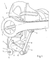
- FIGS. 1 and 2 is the sensor arrangement according to the invention provided on a wheel suspension 1, with a not shown wheel of an otherwise not shown Vehicle is attached to the body 2.
- a bearing bracket 4 is formed on the vehicle body 2, on which the wishbone 3 is pivotable about a pivot axis 5 is stored.
- the pivotable attachment of the wishbone 3 to the vehicle body 2 or at their position console 4 is with the help a bearing bolt 6 designed as a fastening screw manufactured, which penetrates the bearing bracket 4 and with a Screwed pivot bearing of the wishbone 3, not shown is.
- the aforementioned swivel bearing is in one eye 7 of the wishbone 3 arranged and for clarity not shown.
- the bearing pin 6 penetrates the bearing bracket 4 in one for it provided, but not visible in FIGS. 1 and 2 Opening through which the relative position of the pivot axis 5 with respect the vehicle body 2 is set.
- To the in the frame of the assembly of the suspension add up Compensate for manufacturing and assembly tolerances of the individual components, becomes the aforementioned opening for the bearing pin 6 on the vehicle body, which is otherwise largely completed 2 retrofitted.
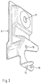
- Wishbone 3 becomes a sensor holder with the help of the bearing pin 6 8 attached to the vehicle body 2.
- the sensor holder 8 according to Kind of a washer on the pivot arm of the wishbone 3 opposite side of the bearing bracket 4 between the head of the bearing pin 6 and the bearing bracket 4 clamped.
- the bearing pin 6 or the one in the bearing bracket 4 provided opening thus forms for the wishbone 3 and the sensor holder 8 a common attachment point on the Vehicle body 2.
- the sensor 9 has a pivot lever 10 which supported at one end on a pivot lever axis 11 on the sensor 9 and is articulated at the other end with a control rod 12 connected is.
- the control rod 12 is in turn on her from Swivel lever 10 remote end at an articulation point 13 articulated connected to the wishbone 3. That way the sensor 9 is mechanically coupled to the wishbone 3. Swivel movements of the control arm 3 about its swivel axis 5 are transmitted from the control rod 12 to the pivot lever 10 and thus detected by the sensor 9.
- the relative position of the control arm 3 and thus the vehicle wheel coupled to it relative to the vehicle body be detected and for example in the form signal values generated by the sensor 9 to a level control device to get redirected.
- the pivot axis 5 of the wishbone 3 and preferably parallel pivot arm axis 11 on sensor 9 have a defined distance from each other.
- the wishbone 3 On the other hand must be in the presence of a reference position or relative starting position the wishbone 3 a defined output deflection or the starting position for the pivot lever 10 is maintained become.
- the aforementioned angle can thereby be set be that the sensor holder 8 in a certain Relative position with respect to the vehicle body 2 attached to this becomes.
- positioning means 14 and 15 intended.
- the tongue 14 extends from the sensor holder 8 approximately parallel to the pivot axis 5 in the direction on the bearing bracket 4. With the sensor holder 8 the tongue 14 penetrates the opening 15.
- the positioning means (Tongue 14 and opening 15) Play on. Because the positioning means (14 and 15) approximately vertically below the attachment point (Bearing pin 6) of the sensor holder 8 on the vehicle body 2 are arranged, the game mentioned essentially be formed only in the vertical direction. This vertical game is thereby in the illustrated embodiment achieved that the opening 15 as a vertically extending slot is trained.
- Deviations occurring between the desired target relative position the sensor holder 8 with respect to the wishbone 3 in its reference position, for example by a electronic calibration can be compensated for at due to the arrangement of the pivot lever 10 and control rod 12 hardly any impairment for the measuring range or the measuring accuracy of the sensor 9 results.
- the tongue 14 of the sensor holder 8 is on their free end converged.
- automated assembly of the sensor holder 8 simplified, since in the course of a machine-carried out Sliding the previous tip of the tongue 14 slightly can penetrate into the opening 15.
- slip-on movement causes the widening tongue 14 a Alignment of the sensor holder 8 relative to the vehicle body 2.
- openings 16 are provided, which for Serve positioning and attachment of the sensor 9.
- the sensor holder 8 has an opening 17 through which the Bearing pin 6 for attaching the sensor holder 8 to the Vehicle body 2 penetrates the sensor holder 8.
- the vehicle body 2 Since according to the invention a common attachment point of the bearing pin 6 for a sensor-side fastening element (Sensor holder 8) and a swivel arm-side fastening element (not shown pivot arm of the wishbone 3) the vehicle body 2 is provided, manufacturing and assembly tolerances of all other components of the Suspension 1 does not depend on the distance of the sensor 9 Impact pivot axis 5. A tolerance compensation is in this regard therefore no longer necessary.
- the Manufacture of the sensor holder 8 to pay particular attention to that on the one hand the relative position of the openings 16 for the Attachment of the sensor 9 with respect to the opening 17 for the Bearing pin 6 in a comparatively narrow tolerance range be formed.
- the openings mentioned 16 and 17 have centering properties, such as due to a tight fit, especially a press fit, can be realized.
- Sensor holder 8 can also correspond to a housing of sensor 9 be trained and e.g. the opening 17 for the bearing pin 6 included and with appropriate positioning be equipped.
Landscapes
- Engineering & Computer Science (AREA)
- Mechanical Engineering (AREA)
- Vehicle Body Suspensions (AREA)
- Length Measuring Devices With Unspecified Measuring Means (AREA)
Abstract
Description
- Fig. 1
- eine perspektivische Frontansicht auf eine Sensoranordnung an einer nur teilweise dargestellten Radaufhängung,
- Fig. 2
- eine perspektivische Rückansicht auf die Sensoranordnung aus Fig. 1 und
- Fig. 3
- eine räumliche Darstellung eines Sensorhalters nach der Erfindung.
Claims (12)
- Sensoranordnung an einer Radaufhängung für ein Fahrzeug, bei der ein Schwenkarm an einer Fahrzeugkarosserie schwenkbar gelagert ist und bei der ein Sensor zur Detektion der Relativlage zwischen Schwenkarm und Fahrzeugkarosserie ortsfest an der Fahrzeugkarosserie angebracht und mechanisch mit dem Schwenkarm gekoppelt ist,
dadurch gekennzeichnet,daß ein sensorseitiges Befestigungselement und ein schwenkarmseitiges Befestigungselement an einer gemeinsamen Befestigungsstelle (6) an der Fahrzeugkarosserie (2) befestigt sind,
wobei das sensorseitige Befestigungselement durch eine sensorfeste Sensorhalterung (8) gebildet ist und wobei das schwenkarmseitige Befestigungselement ein Schwenklager des Schwenkarmes (3) ist, durch das der Schwenkarm (3) an der Fahrzeugkarosserie (2) schwenkbar befestigt ist. - Sensoranordnung nach Anspruch 1,
dadurch gekennzeichnet,daß die Sensorhalterung ein als separates Bauteil ausgebildeter Sensorhalter (8) ist, an dem der Sensor (9) befestigt ist. - Sensoranordnung nach Anspruch 1 oder 2,
dadurch gekennzeichnet,daß die gemeinsame Befestigungsstelle von sensorseitigem Befestigungselement (8) und schwenkarmseitigen Befestigungselement durch einen die Schwenkachse (5) des Schwenkarmes (3) bildenden Lagerbolzen (6) gebildet ist, daß das schwenkarmseitige Befestigungselement durch den Lagerbolzen (6) schwenkbar an der Fahrzeugkarosserie (2) befestigt ist unddaß das sensorseitige Befestigungselement (8) eine Paßbohrung (17) für den Lagerbolzen (6) enthält. - Sensoranordnung nach Anspruch 3,
dadurch gekennzeichnet,daß der Lagerbolzen (6) als Befestigungsschraube ausgebildet ist, mit der das sensorseitige Befestigungselement (8) zusammen mit dem schwenkarmseitigen Befestigungselement an der Fahrzeugkarosserie (2) befestigt ist. - Sensoranordnung nach einem der vorhergehenden Ansprüche,
dadurch gekennzeichnet,daß Positioniermittel (14,15) vorgesehen sind, die zum Auffinden einer vorgegebenen Relativlage des sensorseitigen Befestigungselementes (8) bezüglich der Fahrzeugkarosserie (2) dienen. - Sensoranordnung nach Anspruch 5,
dadurch gekennzeichnet,daß die Positioniermittel eine von der Schwenkachse (5) beabstandete Zunge (14) sowie eine Öffnung (15) aufweisen, in welche die Zunge zur (14) Positionierung eindringt. - Sensoranordnung nach Anspruch 6,
dadurch gekennzeichnet,daß die Öffnung (15) als Langloch ausgebildet ist, wobei die in das Langloch einragende Zunge (14) Spiel in etwa radialer Richtung bezüglich der Schwenkachse (5) des Schwenkarmes (3) aufweist. - Sensoranordnung nach Anspruch 6 oder 7,
dadurch gekennzeichnet,daß sich die Zunge (14) zu ihrem freien Ende hin verjüngt und in einem davon abgewandten Abschnitt im wesentlichen ein Außenmaß aufweist, das dem lichten Innenmaß der Öffnung (15) entspricht. - Sensoranordnung nach einem der Ansprüche 2 bis 5 und einem der Ansprüche 6 bis 8,
dadurch gekennzeichnet,daß die Zunge (14) am Sensorhalter (8) ausgebildet ist unddaß die Öffnung (15) in der Fahrzeugkarosserie (2) vorgesehen ist. - Sensoranordnung nach einem der vorhergehenden Ansprüche,
dadurch gekennzeichnet,daß der Schwenkarm als Querlenker (3) der Radaufhängung (1) ausgebildet ist. - Sensoranordnung nach einem der vorhergehenden Ansprüche,
dadurch gekennzeichnet,daß der Sensor (9) ein Hubsensor ist, der an eine Niveauregulierung des Fahrzeuges angeschlossen ist. - Sensorhalter zum Befestigen eines Sensors (9) an einer Fahrzeugkarosserie (2) zur Ausbildung einer Sensoranordnung nach einem der Ansprüche 2 bis 11.
Applications Claiming Priority (2)
| Application Number | Priority Date | Filing Date | Title |
|---|---|---|---|
| DE19831248 | 1998-07-11 | ||
| DE19831248A DE19831248C2 (de) | 1998-07-11 | 1998-07-11 | Sensoranordnung an einer Radaufhängung für ein Fahrzeug |
Publications (2)
| Publication Number | Publication Date |
|---|---|
| EP0972660A1 true EP0972660A1 (de) | 2000-01-19 |
| EP0972660B1 EP0972660B1 (de) | 2002-12-18 |
Family
ID=7873820
Family Applications (1)
| Application Number | Title | Priority Date | Filing Date |
|---|---|---|---|
| EP99111629A Expired - Lifetime EP0972660B1 (de) | 1998-07-11 | 1999-06-16 | Sensoranordnung an einer Radaufhängung für ein Fahrzeug |
Country Status (4)
| Country | Link |
|---|---|
| US (1) | US6126177A (de) |
| EP (1) | EP0972660B1 (de) |
| JP (1) | JP2000079817A (de) |
| DE (1) | DE19831248C2 (de) |
Cited By (3)
| Publication number | Priority date | Publication date | Assignee | Title |
|---|---|---|---|---|
| WO2008074309A1 (de) * | 2006-12-21 | 2008-06-26 | Zf Friedrichshafen Ag | Radaufhängung für ein fahrzeug |
| DE102014012587A1 (de) | 2014-08-26 | 2016-03-03 | Audi Ag | Vorrichtung und Verfahren zur Niveauregulierung an einem Fahrwerk |
| WO2016041832A1 (de) * | 2014-09-17 | 2016-03-24 | Continental Teves Ag & Co. Ohg | Verlagerungsgeber für kraftfahrzeug |
Families Citing this family (19)
| Publication number | Priority date | Publication date | Assignee | Title |
|---|---|---|---|---|
| US6357766B1 (en) * | 1999-11-01 | 2002-03-19 | Dana Corporation | Multi-axis suspension system |
| US6566864B1 (en) * | 2000-09-01 | 2003-05-20 | Ford Global Technologies, L.L.C. | Angular position sensor for vehicle suspension |
| DE10221873A1 (de) * | 2002-05-15 | 2003-11-27 | Zf Lemfoerder Metallwaren Ag | Gummilager mit Einfederungssensor |
| JP2004270832A (ja) * | 2003-03-10 | 2004-09-30 | Advics:Kk | サスペンション用防振装置およびそれを用いたサスペンション機構 |
| DE10333997B4 (de) * | 2003-07-25 | 2014-07-17 | Volkswagen Ag | Sensoranordnung für ein Landfahrzeug |
| US20060220638A1 (en) * | 2005-03-31 | 2006-10-05 | Urquidi Carlos A | Angular position sensor |
| US7370853B2 (en) | 2005-03-31 | 2008-05-13 | Delphi Technologies, Inc. | Vibration isolating bushing with embedded angular position sensor |
| US7360756B2 (en) * | 2005-03-31 | 2008-04-22 | Delphi Technologies, Inc. | Vibration isolating bushing with embedded speed/position sensor |
| KR100736716B1 (ko) | 2007-01-08 | 2007-07-09 | 씨멘스브이디오한라 주식회사 | 자동차용 휠스피드센서와 이의 성형장치 |
| DE102007028265A1 (de) | 2007-06-15 | 2008-12-18 | Ipgate Ag | Drehwinkelgeber |
| JP2009052918A (ja) * | 2007-08-23 | 2009-03-12 | Nippon Soken Inc | タイヤ作用力検出装置 |
| WO2009072566A1 (ja) * | 2007-12-07 | 2009-06-11 | Mitsubishi Electric Corporation | 車速検知ユニット及び車輪装着ユニット |
| US20100308192A1 (en) * | 2008-01-31 | 2010-12-09 | Zf Friedrichshafen Ag | Sensor attachment arrangement |
| USD692061S1 (en) * | 2012-07-10 | 2013-10-22 | Performance Designed Products Llc | Sensor mount |
| WO2016157439A1 (ja) * | 2015-03-31 | 2016-10-06 | 本田技研工業株式会社 | 車輪速センサの支持構造 |
| WO2019210944A1 (en) * | 2018-05-02 | 2019-11-07 | HELLA GmbH & Co. KGaA | Level sensor for detecting a movement of a suspension arm and vehicle assembly with the level sensor |
| DE202020106260U1 (de) * | 2020-11-02 | 2022-02-08 | Dana Italia S.R.L. | Fahrzeugaufhängungssystem mit einem Sensor |
| WO2022162676A1 (en) * | 2021-02-01 | 2022-08-04 | Ree Automotive Ltd. | Apparatus for measuring steering angle |
| DE102022203618A1 (de) * | 2022-04-11 | 2023-10-12 | Dana Italia S.R.L. | Lenksensoranordnung |
Citations (10)
| Publication number | Priority date | Publication date | Assignee | Title |
|---|---|---|---|---|
| GB2028513A (en) * | 1978-06-23 | 1980-03-05 | Atsugi Motor Parts Co Ltd | Vehicle level detector |
| EP0094857A1 (de) * | 1982-05-06 | 1983-11-23 | HURET ET SES FILS Société dite: | Sensorvorrichtung, insbesondere zum Antrieb eines Fahrradtachometers |
| US4756374A (en) * | 1987-03-31 | 1988-07-12 | Bailey John D | Vehicle load sensing device |
| US4838563A (en) * | 1987-05-27 | 1989-06-13 | Nissan Motor Company, Limited | Mounting structure for vehicle height sensor |
| DE3919040A1 (de) | 1989-06-10 | 1990-12-13 | Porsche Ag | Verfahren und vorrichtung zur justierung einer hoehenstands-regelanlage eines fahrzeugs |
| US5032821A (en) * | 1989-05-12 | 1991-07-16 | Domanico Edward J | Motor vehicle stability monitoring and alarm system and method |
| EP0632253A1 (de) * | 1993-06-23 | 1995-01-04 | CTS Corporation | Positionssensoren |
| DE4429856C1 (de) | 1994-08-23 | 1995-09-07 | Daimler Benz Ag | Vorrichtung zum Erkennen des Fahrzeugniveaus |
| JPH08142907A (ja) * | 1994-11-17 | 1996-06-04 | Delta:Kk | 自動車の後輪キャンバ,トラッキング調整装置 |
| JPH09105662A (ja) * | 1995-10-09 | 1997-04-22 | Hino Motors Ltd | タンデム・アクスル・トラニオン型リア・サスペンションに使用される軸重検出装置 |
Family Cites Families (8)
| Publication number | Priority date | Publication date | Assignee | Title |
|---|---|---|---|---|
| NL233622A (de) * | 1957-11-28 | |||
| GB1017391A (en) * | 1961-03-09 | 1966-01-19 | Automotive Prod Co Ltd | Improvements in and relating to valves for fluid pressure braking systems |
| US4553773A (en) * | 1983-08-05 | 1985-11-19 | Lear Siegler, Inc. | Load equalizer valve and suspension system |
| US4614247A (en) * | 1984-10-26 | 1986-09-30 | Airstream, Inc. | Composite multi-axle suspension for vehicles |
| US4982972A (en) * | 1989-12-26 | 1991-01-08 | Eaton Corporation | Hydraulic pump and actuator for parallel auxiliary leaf spring |
| US5033762A (en) * | 1990-02-26 | 1991-07-23 | Rakowski Carl F | Suspension system for a sidecar motorcycle |
| JPH06282368A (ja) * | 1993-02-01 | 1994-10-07 | Wacom Co Ltd | 情報処理装置の位置情報入力システム |
| JPH07287835A (ja) * | 1994-02-25 | 1995-10-31 | Toyo Ink Mfg Co Ltd | 磁気記録媒体 |
-
1998
- 1998-07-11 DE DE19831248A patent/DE19831248C2/de not_active Expired - Lifetime
-
1999
- 1999-06-16 EP EP99111629A patent/EP0972660B1/de not_active Expired - Lifetime
- 1999-07-08 JP JP11227853A patent/JP2000079817A/ja active Pending
- 1999-07-08 US US09/349,099 patent/US6126177A/en not_active Expired - Fee Related
Patent Citations (10)
| Publication number | Priority date | Publication date | Assignee | Title |
|---|---|---|---|---|
| GB2028513A (en) * | 1978-06-23 | 1980-03-05 | Atsugi Motor Parts Co Ltd | Vehicle level detector |
| EP0094857A1 (de) * | 1982-05-06 | 1983-11-23 | HURET ET SES FILS Société dite: | Sensorvorrichtung, insbesondere zum Antrieb eines Fahrradtachometers |
| US4756374A (en) * | 1987-03-31 | 1988-07-12 | Bailey John D | Vehicle load sensing device |
| US4838563A (en) * | 1987-05-27 | 1989-06-13 | Nissan Motor Company, Limited | Mounting structure for vehicle height sensor |
| US5032821A (en) * | 1989-05-12 | 1991-07-16 | Domanico Edward J | Motor vehicle stability monitoring and alarm system and method |
| DE3919040A1 (de) | 1989-06-10 | 1990-12-13 | Porsche Ag | Verfahren und vorrichtung zur justierung einer hoehenstands-regelanlage eines fahrzeugs |
| EP0632253A1 (de) * | 1993-06-23 | 1995-01-04 | CTS Corporation | Positionssensoren |
| DE4429856C1 (de) | 1994-08-23 | 1995-09-07 | Daimler Benz Ag | Vorrichtung zum Erkennen des Fahrzeugniveaus |
| JPH08142907A (ja) * | 1994-11-17 | 1996-06-04 | Delta:Kk | 自動車の後輪キャンバ,トラッキング調整装置 |
| JPH09105662A (ja) * | 1995-10-09 | 1997-04-22 | Hino Motors Ltd | タンデム・アクスル・トラニオン型リア・サスペンションに使用される軸重検出装置 |
Non-Patent Citations (2)
| Title |
|---|
| PATENT ABSTRACTS OF JAPAN vol. 1996, no. 10 31 October 1996 (1996-10-31) * |
| PATENT ABSTRACTS OF JAPAN vol. 1997, no. 08 29 August 1997 (1997-08-29) * |
Cited By (6)
| Publication number | Priority date | Publication date | Assignee | Title |
|---|---|---|---|---|
| WO2008074309A1 (de) * | 2006-12-21 | 2008-06-26 | Zf Friedrichshafen Ag | Radaufhängung für ein fahrzeug |
| US8179128B2 (en) | 2006-12-21 | 2012-05-15 | Zf Friedrichshafen Ag | Wheel suspension for a vehicle |
| DE102014012587A1 (de) | 2014-08-26 | 2016-03-03 | Audi Ag | Vorrichtung und Verfahren zur Niveauregulierung an einem Fahrwerk |
| DE102014012587B4 (de) * | 2014-08-26 | 2016-05-04 | Audi Ag | Vorrichtung und Verfahren zur Niveauregulierung an einem Fahrwerk |
| WO2016041832A1 (de) * | 2014-09-17 | 2016-03-24 | Continental Teves Ag & Co. Ohg | Verlagerungsgeber für kraftfahrzeug |
| CN107076572A (zh) * | 2014-09-17 | 2017-08-18 | 大陆-特韦斯股份有限公司 | 用于机动车的位移传感设备 |
Also Published As
| Publication number | Publication date |
|---|---|
| DE19831248A1 (de) | 2000-01-20 |
| JP2000079817A (ja) | 2000-03-21 |
| US6126177A (en) | 2000-10-03 |
| EP0972660B1 (de) | 2002-12-18 |
| DE19831248C2 (de) | 2002-09-19 |
Similar Documents
| Publication | Publication Date | Title |
|---|---|---|
| DE19831248C2 (de) | Sensoranordnung an einer Radaufhängung für ein Fahrzeug | |
| DE19739298C1 (de) | Vorrichtung zur Befestigung eines Entfernungssensors an einem Kraftfahrzeug | |
| EP1444114B1 (de) | Halterung für ein justierbares gehäuse | |
| EP4178816B1 (de) | Fahrwerkbauteil mit einem gelenkinnenteil | |
| DE10304259B4 (de) | Befestigung für eine Anzeigeeinheit | |
| WO1992008136A1 (de) | Vorrichtung zum positionieren eines sensors | |
| EP4157652B1 (de) | Fahrwerkbauteil und verfahren zum herstellen eines solchen fahrwerkbauteils | |
| EP2828680A1 (de) | Sensorhalterung für einen sensor zur objektdetektion | |
| DE102021121798A1 (de) | Türantriebsvorrichtung mit einer Sensoreinrichtung zur Messung einer Kraft im Kraftfluss | |
| DE102007002699A1 (de) | Befestigungseinrichtung insbesondere für einen Kraftwagen | |
| DE102021103364B9 (de) | Kalibriereinheit zur Ausrichtung von Fahrzeugumfelderfassungseinheiten eines Kraftfahrzeugs | |
| DE10003981C2 (de) | Anordnung zum positionsgerechten Verbinden von Bauteilen | |
| EP1270350A2 (de) | Justiereinrichtung und zugehöriges Betätigungswerkzeug | |
| EP1341642B1 (de) | Verfahren und vorrichtung zum zusammenbau einer fahrzeugtür | |
| DE10103402A1 (de) | Außenrückblickspiegel eines Kraftfahrzeugs | |
| DE102012022783A1 (de) | Befestigungsanordnung an einem Fahrzeug sowie Fahrzeug | |
| DE102015119708A1 (de) | Vorrichtung zur Befestigung eines optischen Sensors an einem Kraftfahrzeug mit Justageeinrichtung, Sensoranordnung sowie Kraftfahrzeug | |
| DE102005053181A1 (de) | Vorrichtung für ein Lenksystem eines Kraftfahrzeugs | |
| DE102004005978B4 (de) | Verfahren und Vorrichtung zur Montage von Scheinwerfern an Montageträgern | |
| DE4313739C2 (de) | Vorrichtung zum Befestigen eines zweiten Bauteils an einem ersten Bauteil | |
| DE60014565T2 (de) | Exzentrisch einstellbare Mutter | |
| DE102015119710A1 (de) | Vorrichtung zur Befestigung eines optischen Sensors an einem Kraftfahrzeug mit Federelement, Sensoranordnung sowie Kraftfahrzeug | |
| EP3969916B1 (de) | Drehzahlsensor, fixiereinrichtung für einen drehzahlsensor, aufnahmevorrichtung für einen drehzahlsensor, sensorsystem mit einer aufnahmevorrichtung und einem drehzahlsensor und verfahren zum verdrehsicheren positionieren eines drehzahlsensors | |
| DE19837584C2 (de) | Verfahren zum Befestigen eines Sensors | |
| DE102017219495A1 (de) | Toleranzausgleichssystem zum Einstellen eines Fugenbilds zwischen zwei im Bereich einer Fahrzeugsäule eines Kraftfahrzeugs anzubringenden Außenblenden |
Legal Events
| Date | Code | Title | Description |
|---|---|---|---|
| PUAI | Public reference made under article 153(3) epc to a published international application that has entered the european phase |
Free format text: ORIGINAL CODE: 0009012 |
|
| AK | Designated contracting states |
Kind code of ref document: A1 Designated state(s): FR GB IT SE |
|
| AX | Request for extension of the european patent |
Free format text: AL;LT;LV;MK;RO;SI |
|
| 17P | Request for examination filed |
Effective date: 19991201 |
|
| AKX | Designation fees paid |
Free format text: FR GB IT SE |
|
| 17Q | First examination report despatched |
Effective date: 20011210 |
|
| REG | Reference to a national code |
Ref country code: DE Ref legal event code: 8566 |
|
| GRAH | Despatch of communication of intention to grant a patent |
Free format text: ORIGINAL CODE: EPIDOS IGRA |
|
| GRAH | Despatch of communication of intention to grant a patent |
Free format text: ORIGINAL CODE: EPIDOS IGRA |
|
| GRAA | (expected) grant |
Free format text: ORIGINAL CODE: 0009210 |
|
| PUAC | Information related to the publication of a b1 document modified or deleted |
Free format text: ORIGINAL CODE: 0009299EPPU |
|
| STAA | Information on the status of an ep patent application or granted ep patent |
Free format text: STATUS: THE APPLICATION HAS BEEN WITHDRAWN |
|
| AK | Designated contracting states |
Kind code of ref document: B1 Designated state(s): FR GB IT SE |
|
| REG | Reference to a national code |
Ref country code: GB Ref legal event code: FG4D Free format text: NOT ENGLISH |
|
| DB1 | Publication of patent cancelled | ||
| 18W | Application withdrawn |
Withdrawal date: 20021116 |
|
| GBV | Gb: ep patent (uk) treated as always having been void in accordance with gb section 77(7)/1977 [no translation filed] |
Effective date: 20021218 |
|
| EN | Fr: translation not filed |