EP0972666B1 - Fensterführungsschiene - Google Patents
Fensterführungsschiene Download PDFInfo
- Publication number
- EP0972666B1 EP0972666B1 EP99113777A EP99113777A EP0972666B1 EP 0972666 B1 EP0972666 B1 EP 0972666B1 EP 99113777 A EP99113777 A EP 99113777A EP 99113777 A EP99113777 A EP 99113777A EP 0972666 B1 EP0972666 B1 EP 0972666B1
- Authority
- EP
- European Patent Office
- Prior art keywords
- glass run
- gutter
- gutters
- set forth
- bottom portion
- Prior art date
- Legal status (The legal status is an assumption and is not a legal conclusion. Google has not performed a legal analysis and makes no representation as to the accuracy of the status listed.)
- Expired - Lifetime
Links
- 239000011521 glass Substances 0.000 title claims description 38
- 238000007599 discharging Methods 0.000 claims description 18
- 229920001971 elastomer Polymers 0.000 claims description 11
- 229920002725 thermoplastic elastomer Polymers 0.000 claims description 9
- 239000006082 mold release agent Substances 0.000 claims description 5
- 239000010734 process oil Substances 0.000 claims description 5
- 239000005357 flat glass Substances 0.000 description 12
- 230000002093 peripheral effect Effects 0.000 description 5
- 239000011347 resin Substances 0.000 description 5
- 229920005989 resin Polymers 0.000 description 5
- 229920002943 EPDM rubber Polymers 0.000 description 4
- 238000000465 moulding Methods 0.000 description 4
- 238000005299 abrasion Methods 0.000 description 3
- 229920001577 copolymer Polymers 0.000 description 3
- 239000000428 dust Substances 0.000 description 3
- 238000001125 extrusion Methods 0.000 description 3
- 239000004576 sand Substances 0.000 description 3
- 238000004073 vulcanization Methods 0.000 description 3
- PPBRXRYQALVLMV-UHFFFAOYSA-N Styrene Chemical compound C=CC1=CC=CC=C1 PPBRXRYQALVLMV-UHFFFAOYSA-N 0.000 description 2
- 150000001336 alkenes Chemical class 0.000 description 2
- 230000007423 decrease Effects 0.000 description 2
- 238000000034 method Methods 0.000 description 2
- 238000012986 modification Methods 0.000 description 2
- 230000004048 modification Effects 0.000 description 2
- JRZJOMJEPLMPRA-UHFFFAOYSA-N olefin Natural products CCCCCCCC=C JRZJOMJEPLMPRA-UHFFFAOYSA-N 0.000 description 2
- 239000004698 Polyethylene Substances 0.000 description 1
- 230000015572 biosynthetic process Effects 0.000 description 1
- 230000000740 bleeding effect Effects 0.000 description 1
- 238000004891 communication Methods 0.000 description 1
- 230000000694 effects Effects 0.000 description 1
- 235000012438 extruded product Nutrition 0.000 description 1
- 238000001746 injection moulding Methods 0.000 description 1
- 239000000463 material Substances 0.000 description 1
- -1 polyethylene Polymers 0.000 description 1
- 229920000573 polyethylene Polymers 0.000 description 1
- 238000007789 sealing Methods 0.000 description 1
- 239000007787 solid Substances 0.000 description 1
Images




Classifications
-
- B—PERFORMING OPERATIONS; TRANSPORTING
- B60—VEHICLES IN GENERAL
- B60J—WINDOWS, WINDSCREENS, NON-FIXED ROOFS, DOORS, OR SIMILAR DEVICES FOR VEHICLES; REMOVABLE EXTERNAL PROTECTIVE COVERINGS SPECIALLY ADAPTED FOR VEHICLES
- B60J10/00—Sealing arrangements
- B60J10/20—Sealing arrangements characterised by the shape
- B60J10/27—Sealing arrangements characterised by the shape having projections, grooves or channels in the longitudinal direction
-
- B—PERFORMING OPERATIONS; TRANSPORTING
- B60—VEHICLES IN GENERAL
- B60J—WINDOWS, WINDSCREENS, NON-FIXED ROOFS, DOORS, OR SIMILAR DEVICES FOR VEHICLES; REMOVABLE EXTERNAL PROTECTIVE COVERINGS SPECIALLY ADAPTED FOR VEHICLES
- B60J10/00—Sealing arrangements
- B60J10/15—Sealing arrangements characterised by the material
- B60J10/17—Sealing arrangements characterised by the material provided with a low-friction material on the surface
-
- B—PERFORMING OPERATIONS; TRANSPORTING
- B60—VEHICLES IN GENERAL
- B60J—WINDOWS, WINDSCREENS, NON-FIXED ROOFS, DOORS, OR SIMILAR DEVICES FOR VEHICLES; REMOVABLE EXTERNAL PROTECTIVE COVERINGS SPECIALLY ADAPTED FOR VEHICLES
- B60J10/00—Sealing arrangements
- B60J10/20—Sealing arrangements characterised by the shape
- B60J10/21—Sealing arrangements characterised by the shape having corner parts or bends
-
- B—PERFORMING OPERATIONS; TRANSPORTING
- B60—VEHICLES IN GENERAL
- B60J—WINDOWS, WINDSCREENS, NON-FIXED ROOFS, DOORS, OR SIMILAR DEVICES FOR VEHICLES; REMOVABLE EXTERNAL PROTECTIVE COVERINGS SPECIALLY ADAPTED FOR VEHICLES
- B60J10/00—Sealing arrangements
- B60J10/70—Sealing arrangements specially adapted for windows or windscreens
- B60J10/74—Sealing arrangements specially adapted for windows or windscreens for sliding window panes, e.g. sash guides
Definitions
- This invention relates to the formation of a glass run for slidably receiving the peripheral edge of a moving window glass so as to guide the movement of the window glass, for sealing between the window glass and a door sash, and for including an internal debris discharge system.
- the glass run 50 shown in Figs. 6 to 8.
- the glass run 50 is attached to a door sash 1 of an automobile (see Fig. 4) and seals between the outer peripheral edge of a raised (closed) door window glass 2 and the door sash 1.
- the glass run 50 comprises a plurality of straight extruded parts 51 and curved or bent molded parts 61 which are formed by being injected into a mold cavity each of which connects together two of the straight extruded parts 51.
- the extruded part 51 is attached to a straight section of the door sash 1 while the molded part 61 is attached to a corner section of the door sash 1.
- the letter “S” designates a borderline, or the connected end surfaces, between the extruded part 51 and the molded part 61.
- the extruded part 51 shown in Fig. 7 comprises a channel portion 54 which consists of a bottom portion 52, two side walls 53, and two seal lips 55 which project into the channel portion. 54 from free ends of the both side walls 53.
- the molded part 61 shown in Fig. 8, comprises a channel portion 64 which consists of a bottom portion 62 having a solid flat interior surface, two side walls 63, and two seal lips 65 which project into the channel portion 64 from free ends of the both side walls 63.
- the end face of the outer peripheral edge of the door window glass 2 slides on the surfaces of the bottom portions 52,62. Therefore, there is a concern that the surfaces of the bottom portions 52, 62 may be easily abraded. Further, if debris such as sand or dust becomes inserted between the surfaces of the bottom portions 52, 62 and the end face of the window glass 2, abrasion of these surfaces will be accelerated in advance of normal conditions.
- gutters or ditches 57 are formed in the longitudinal direction along the interior of bottom portion 52 of the straight extruded part 51 with small cross-sectional areas. Gutters 57 are formed simultaneously when the channel portion 54 and the seal lips 55 are formed by extrusion.
- EP-A-0 900 680 which falls under Art 54(3) EPC, discloses a glass run identically to the molding made of an ethylene-propylene-diene copolymer (EPDM) rubber to form the extruded part 51 as a single product, as shown in Fig. 7. With such a structure for the extruded part 51, debris moves and drops into the gutters 57 and is discharged when the window glass 2 slides on the surface of the bottom portion 52.
- EPDM ethylene-propylene-diene copolymer
- no gutter arrangement is formed on the interior surface of the bottom portion 62 of the molded part 61, as shown in Fig. 8. Therefore, as for the molded part 61, the above-described operation of discharging debris is not achieved.
- the reason why no gutter is formed for the molded part 61 is thought to be as follows. Namely, even if gutters having small cross-sectional areas are to be formed, it is known that a bleeding mold release agent or process oil, or a generated vulcanization gas easily fills such gutters when the channel portion 64 and the seal lips 65 are molded from an EPDM rubber to form the molded part 61 as a single product. Therefore, no gutter has came to be actually formed.
- a molded rubber is inferior to an extruded rubber in durability, even though both are formed from the same type EPDM rubber.
- the present invention resides in a glass run which comprises at least one molded part that includes a channel portion with a bottom portion, side walls, seal lips projecting from the side walls and one or more gutters formed on the surface of the bottom portion for discharging debris.
- the molded part is preferably formed from a rubber, a soft resin or a thermoplastic elastomer (TPE).
- rubber embraces an ethylene-propylene-diene copolymer (EPDM) rubber and an ethylene-propylene copolymer rubber (EPR).
- soft resin embraces an olefin soft resin including a soft polyethylene.
- TPE embraces an olefin TPE (TPO) and a styrene TPE (SBC).
- a soft resin or a TPE is preferable than a rubber.
- a gutter for discharging debris may have a V-shaped, U-shaped or rectangular cross section.
- gutters designed for a molded part formed from a rubber preferably have a large cross-sectional area of the order of 0.15 - 0.5 mm 2 so that the gutters will not be completely filled with mold release agent, process oil or vulcanization gas.
- the width of the gutter for discharging debris is preferably about 0.4 - 0.7 mm while the depth thereof is preferably about 0.4 - 0.7 mm.
- the direction in which the gutters for discharging debris are formed is not specifically limited, they are preferably provided in the longitudinal direction along the bottom portion.
- 1 - 5 gutters are preferably provided with a pitch between centers of adjacent gutters being about 1 - 3 mm.
- gutters for discharging debris may be formed in a slantwise direction relative to the longitudinal direction of the bottom portion so they open in such grooves.
- the angle at which the gutters slant with respect to the longitudinal direction of the bottom portion is not specifically limited, but an angle from about 45 to about 75 degrees is preferable.
- Such slantwise positioned gutters are preferably provided with a pitch between centers of adjacent gutters of about 4 to about 6 mm.
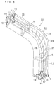
- a glass run 10 of a first embodiment is shown in Figs. 1 to 3.
- This glass run 10 comprises a plurality of straight extruded parts 11, portions of which are shown in Fig. 1, and curved or bent molded parts 21 which connect two extruded parts 11.
- An extruded part 11 is attached to a straight section of the door sash 1, while the curved molded part 21 is attached to follow a corner section of the door sash 1.
- the letter “S” designates a borderline, or the connected end surfaces, between an extruded part 11 and a molded part 21.
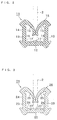
- the extruded part 11 the cross-section of which is shown in Fig. 2, comprises a channel portion 14 which includes a bottom portion 12, two side walls 13, and two seal lips 15 which project into the interior space 18 of channel portion 14 from the free ends of each side wall 13.
- the molded part 21 shown in Fig. 3 comprises a channel portion 24 which includes a bottom portion 22, two side walls 23, and two seal lips 25 which project into the interior space 28 of channel portion 24 from the free ends of each side wall 23.
- the channel portion 14 and the seal lips 15 are formed by extrusion molding preferably made of a TPO or an EPDM type rubber with the extruded part 11 being formed as a single extruded product. Simultaneously with this extrusion molding, interior grooves 16 are formed longitudinally along back side of the bottom portion 12 with a relatively large cross-sectional area. Three gutters 17 are also formed in a longitudinal direction along the interior surface of bottom portion 12 and have small cross-sectional areas. Gutters 17 are provided to allow the discharge of debris such as sand or dust. Each gutter 17 has a V-shaped cross-section, about 0.5 mm in width, 0.5 mm in depth and 1.5 mm in pitch between the centers of adjacent gutters.
- the channel portion 24 and the seal lips 25 are molded from a TPO to form the molded part 21 as a single product.
- interior grooves 26 are formed in the longitudinal direction on both sides of the bottom portion 22 and have large cross-sectional areas.
- Three interior gutters 27 are also formed in the longitudinal direction on the interior surface of the bottom portion 22 and have small cross sectional areas. Gutters 27 are provided to allow the discharge of debris and have the same cross-sectional shape, width, depth and pitch between centers of adjacent gutters, as described above for gutters 17.
- Each end of a gutter 27 corresponds to an end of a similarly positioned gutter 17 and they are in relative communication with each other when parts 11 and 21 are connected together.
- the molding process that forms part 21 relative to parts 11 starts with ends of two extruded parts 11 being first set in a mold (not shown) thereby defining a cavity between those two ends. Then, a predetermined amount of TPO is injected into the mold cavity (an injection molding technique is preferably employed here) to thereby form a molded part 21 with its grooves 26 and gutters 27 for discharging debris. Simultaneously with this molding, end surfaces of the extruded parts 11 are connected to the resulting molded part 21. Since both parts 11, 21 are formed from TPO type material and have high compatibility (adhesivity) to each other, they are firmly connected.
- the gutters 17, 27 for discharging debris are formed in the longitudinal direction along the interior surface of bottom portions 12, 22, respectively. Debris such as sand or dust may be collected between the surfaces of bottom portions 12, 22 and the end face of the window glass 2. However, since the gutters 17, 27 are formed along the interior surfaces of the bottom portions 12, 22, the debris will move and drop into the gutters 17, 27 when the window glass 2 slides on the surfaces of the bottom portions 12, 22 with such debris moving along the gutters 17, 27 and be discharged. Considering the direction in which the glass run 10 is attached, the longitudinal direction of the bottom portions 12, 22 often corresponds to the vertical or slantwise up and down direction of the door sash 1. Therefore, the debris gradually falls within the vertical gutters 17, 27 and is discharged.
- Fig. 5 shows a glass run 30 of a second embodiment of this invention.
- the glass run 30 differs from the glass run 10 of the first embodiment by employing a plurality of gutters 27 positioned to be slantwise with respect to the longitudinal direction of the bottom portion 22 of the molded part 21, with both ends of each gutter 27 opening into the grooves 26.
- a gutter 27 can slant at an angle of about 60 degrees with respect to the longitudinal direction of the bottom portion 22.
- the pitch between centers of adjacent gutters 27 is about 5 mm.
- each gutter 27 is provided to discharge debris and otherwise has the same cross-sectional shape, width and depth as disclosed above for gutters 17.
- a glass run comprised of at least one molded part.
- the molded part comprises a channel portion having a bottom portion, side walls, seal lips projecting from the side walls and one or more gutters provided on the surface of the bottom portion for discharging debris.
Landscapes
- Engineering & Computer Science (AREA)
- Mechanical Engineering (AREA)
- Seal Device For Vehicle (AREA)
- Window Of Vehicle (AREA)
- Extrusion Moulding Of Plastics Or The Like (AREA)
Claims (17)
- Glasführungsschiene (10), die mindestens einen geformten Teil (21) hat, der durch Einspritzung in einen Formhohlraum ausgebildet ist, und einen Kanalabschnitt (24) hat, der einen Bodenabschnitt (22) und Seitenwände (23) hat, wobei Dichtlippen (25) von den Seitenwänden (23) vorspringen, wobei eine oder mehr Rinnen (27) auf einer inneren Fläche des Bodenabschnitts (22) zum Ausgeben von Fremdstoffen ausgebildet sind.
- Glasführungsschiene (10) nach Anspruch 1, wobei die Rinnen (27) zum Ausgeben von Fremdstoffen in die Längsrichtung entlang des Bodenabschnitts (22) ausgebildet sind.
- Glasführungsschiene (10) nach Anspruch 2, wobei eine bis fünf Rinnen (27) vorgesehen sind.
- Glasführungsschiene (10) nach Anspruch 2, wobei mindestens zwei Rinnen (27) mit einem Abstand zwischen ihren Mitten von ungefähr 1 bis ungefähr 3 mm vorgesehenen sind.
- Glasführungsschiene (10) nach Anspruch 1, wobei Nuten (26) an beiden Seiten des Bodenabschnitts (22) in eine Längsrichtung entlang des Bodenabschnitts (22) ausgebildet sind, und wobei die Rinnen (27) geneigt in Bezug auf die Längsrichtung des Bodenabschnitts (22) positioniert sind und in die Nuten (26) öffnen.
- Glasführungsschiene (10) nach Anspruch 5, wobei ein Neigungswinkel jeder Rinne (27) in Bezug auf die Längsrichtung des Bodenabschnitts (22) sich im Bereich von ungefähr 45 bis ungefähr 75 Grad befindet.
- Glasführungsschiene (10) nach Anspruch 5, wobei eine Mehrzahl von Rinnen (27) mit einem Abstand zwischen Mitten von benachbarten Rinnen (27) von ungefähr 4 bis ungefähr 6 mm vorgesehen sind.
- Glasführungsschiene, die mindestens einen geformten Teil (21), der durch Einspritzen in einen Formhohlraum ausgebildet wird, und mindestens zwei extrudierte Teile (11) hat,
wobei der geformte Teil (21) einen Kanalabschnitt (24) hat, der einen Bodenabschnitt (22) und Seitenwände (23) hat, wobei Dichtlippen (25) von den Seitenwänden (23) vorspringen,
wobei das extrudierte Teil (11) einen Kanalabschnitt (14), der einen Bodenabschnitt (12) und Seitenwände (13) hat, wobei Dichtlippen (15) von den Seitenwänden (13) vorspringen, und eine oder mehrere Rinnen (17) zum Ausgeben von Fremdstoffen hat, die auf einer inneren Fläche des Bodenabschnitts (12) ausgebildet sind,
wobei die extrudierten Teile (11) und der geformte Teil (21) miteinander verbunden ist,
dadurch gekennzeichnet, dass
eine oder mehrere Rinnen (27) zum Ausgeben von Fremdstoffen auf einer Innenfläche des Bodenabschnitts (22) des geformten Teils (21) ausgebildet sind. - Glasführungsschiene (10) nach Anspruch 8, wobei die Rinnen (27) des geformten Teils (21) mit den Rinnen (17) des extrudierten Teils (11) verbunden sind.
- Glasführungsschiene (10) nach Anspruch 8, wobei die extrudierten Teile (11) und der geformte Teil (21) aus einem thermoplastischen Elastomer gebildet sind, und jede Rinne (17, 27) zum Ausgeben von Fremdstoffen einen V-förmigen, U-förmigen oder rechtwinkeligen Querschnitt hat.
- Glasführungsschiene nach Anspruch 8, wobei der mindestens eine geformte Teil (21) aus Gummi gebildet ist und jede geformte Rinne (27) eine ausreichend große Querschnittsfläche hat, so dass die geformte Rinne (27) nicht vollständig mit Formlösemittel oder Prozessöl gefüllt wird, das in dem Gummi enthalten ist.
- Glasführungsschiene nach Anspruch 10, wobei jede geformte Rinne (27) eine Querschnittsfläche von ungefähr 0,15 bis ungefähr 0,5 mm2 hat.
- Glasführungsschiene nach Anspruch 8, wobei jede Rinne (17, 27) der mindestens einen extrudierten Rinne (17) und der mindestens einen geformte Rinne (27) eine Breite von ungefähr 0,4 bis ungefähr 0,7 mm hat.
- Glasführungsschiene nach Anspruch 8, wobei jede Rinne (17, 27) der mindestens einen extrudierten Rinne (17) und der mindestens einen geformten Rinne (27) eine Tiefe von ungefähr 0,4 bis ungefähr 0,7 mm hat.
- Glasführungsschiene nach Anspruch 8, wobei der mindestens eine extrudierte Teil (11) und der mindestens eine geformte Teil (21) aus einem thermoplastischen Elastomer ausgebildet ist.
- Glasführungsschiene nach Anspruch 14, wobei jede Rinne (17, 27), der mindestens einen extrudierten Rinne (17) und der mindestens einen geformten Rinne (27), eine Breite von ungefähr 0,4 bis ungefähr 0,7 mm hat.
- Glasführungsschiene nach Anspruch 14, wobei jede Rinne (17, 27) der mindestens einen extrudierten Rinne (17) und der mindestens einen geformten Rinne (27) eine Tiefe von ungefähr 0,4 bis ungefähr 0,7 mm hat.
Applications Claiming Priority (2)
| Application Number | Priority Date | Filing Date | Title |
|---|---|---|---|
| JP21858398 | 1998-07-15 | ||
| JP10218583A JP2000025462A (ja) | 1998-07-15 | 1998-07-15 | ガラスラン |
Publications (2)
| Publication Number | Publication Date |
|---|---|
| EP0972666A1 EP0972666A1 (de) | 2000-01-19 |
| EP0972666B1 true EP0972666B1 (de) | 2003-03-19 |
Family
ID=16722237
Family Applications (1)
| Application Number | Title | Priority Date | Filing Date |
|---|---|---|---|
| EP99113777A Expired - Lifetime EP0972666B1 (de) | 1998-07-15 | 1999-07-14 | Fensterführungsschiene |
Country Status (4)
| Country | Link |
|---|---|
| US (1) | US6226926B1 (de) |
| EP (1) | EP0972666B1 (de) |
| JP (1) | JP2000025462A (de) |
| DE (1) | DE69905986T2 (de) |
Cited By (1)
| Publication number | Priority date | Publication date | Assignee | Title |
|---|---|---|---|---|
| CN110154706A (zh) * | 2019-05-22 | 2019-08-23 | 北京汽车集团越野车有限公司 | 一种密封条接角结构及车辆 |
Families Citing this family (12)
| Publication number | Priority date | Publication date | Assignee | Title |
|---|---|---|---|---|
| JP3812310B2 (ja) * | 1999-11-30 | 2006-08-23 | 豊田合成株式会社 | ガラスラン |
| JP3885470B2 (ja) * | 2000-08-23 | 2007-02-21 | 豊田合成株式会社 | 車両用ガラスランおよびその製造方法 |
| JP4001050B2 (ja) * | 2003-04-28 | 2007-10-31 | 豊田合成株式会社 | 自動車用ウエザストリップの製造方法 |
| JP2005008140A (ja) | 2003-05-26 | 2005-01-13 | Toyoda Gosei Co Ltd | 自動車用ガラスラン |
| US20050120633A1 (en) * | 2003-11-26 | 2005-06-09 | Tomohiro Takase | Glass run for vehicle |
| JP4375072B2 (ja) * | 2004-03-23 | 2009-12-02 | 豊田合成株式会社 | 自動車用ガラスラン |
| JP2011126467A (ja) * | 2009-12-21 | 2011-06-30 | Toyoda Gosei Co Ltd | ガラスラン |
| US8469981B2 (en) * | 2010-02-11 | 2013-06-25 | Ethicon Endo-Surgery, Inc. | Rotatable cutting implement arrangements for ultrasonic surgical instruments |
| JP5711528B2 (ja) * | 2010-12-22 | 2015-04-30 | 西川ゴム工業株式会社 | ウェザーストリップの排水構造 |
| US10480194B1 (en) * | 2012-05-18 | 2019-11-19 | David A Szafranski | Gutter cover |
| US20130305621A1 (en) * | 2012-05-18 | 2013-11-21 | David Szafranski | Gutter Garter |
| USD832758S1 (en) * | 2016-11-16 | 2018-11-06 | Shiroki Corporation | Door channel |
Family Cites Families (8)
| Publication number | Priority date | Publication date | Assignee | Title |
|---|---|---|---|---|
| US4454687A (en) * | 1982-10-20 | 1984-06-19 | J. I. Case Company | Guide and support assembly for a window pane |
| JPS6343819A (ja) | 1986-08-09 | 1988-02-24 | Toyoda Gosei Co Ltd | 自動車用ドアガラスラン |
| DE3789701T2 (de) * | 1986-10-30 | 1994-08-11 | Mitsui Petrochemical Industries, Ltd., Tokio/Tokyo | Laminat und aus diesem hergestellter geformter Gegenstand. |
| JPH0625385Y2 (ja) | 1988-05-09 | 1994-07-06 | 豊田合成株式会社 | 自動車用ドアガラスランのシール構造 |
| JP2586241B2 (ja) | 1991-06-07 | 1997-02-26 | 豊田合成株式会社 | ガラスラン |
| US5694718A (en) * | 1995-05-10 | 1997-12-09 | Ultra Fab, Inc. | Glass channel for windows |
| DE69826042T2 (de) * | 1997-02-21 | 2005-09-29 | Mitsui Chemicals, Inc. | Fensterführungsschiene |
| JP3336926B2 (ja) | 1997-09-08 | 2002-10-21 | 豊田合成株式会社 | 自動車用ドアガラスラン |
-
1998
- 1998-07-15 JP JP10218583A patent/JP2000025462A/ja active Pending
-
1999
- 1999-07-14 EP EP99113777A patent/EP0972666B1/de not_active Expired - Lifetime
- 1999-07-14 US US09/353,145 patent/US6226926B1/en not_active Expired - Fee Related
- 1999-07-14 DE DE69905986T patent/DE69905986T2/de not_active Expired - Fee Related
Cited By (1)
| Publication number | Priority date | Publication date | Assignee | Title |
|---|---|---|---|---|
| CN110154706A (zh) * | 2019-05-22 | 2019-08-23 | 北京汽车集团越野车有限公司 | 一种密封条接角结构及车辆 |
Also Published As
| Publication number | Publication date |
|---|---|
| DE69905986T2 (de) | 2003-11-27 |
| DE69905986D1 (de) | 2003-04-24 |
| US6226926B1 (en) | 2001-05-08 |
| JP2000025462A (ja) | 2000-01-25 |
| EP0972666A1 (de) | 2000-01-19 |
Similar Documents
| Publication | Publication Date | Title |
|---|---|---|
| US6226926B1 (en) | Glass run | |
| EP0978404B1 (de) | Dichtungsstreifen | |
| CA1322216C (en) | Window pane sealing strip having a rigid non-reinforced glass-run channel | |
| CA2586318C (en) | Glass run | |
| EP1388449B1 (de) | Dichtungsstreifen für Kraftfahrzeuge | |
| US7055285B2 (en) | Trim and glass run attachment structure in vehicle door | |
| EP0900680B1 (de) | Kraftfahrzeug-Türfensterscheiben-Führungskanal | |
| US7648188B2 (en) | Glass run mounting structure | |
| US8196354B2 (en) | Glass run for motor vehicle | |
| US7281354B2 (en) | Weather strip | |
| CA2042747C (en) | Door glass run for motor vehicle | |
| US6243989B1 (en) | Weather strip and method of forming the same | |
| US6502832B2 (en) | Automotive seal component for vehicle door | |
| KR100365840B1 (ko) | 웨더 스트립 | |
| EP0164601B1 (de) | Autotürfensterführung | |
| US6814393B2 (en) | Sealing strip and vehicle panel assembly | |
| US6792718B2 (en) | Vehicle seal | |
| US6520563B2 (en) | Weather strip | |
| CN100522675C (zh) | 玻璃运行槽 | |
| JP2003165340A (ja) | 自動車用ガラスラン | |
| JP3744303B2 (ja) | 自動車ドア用ウエザストリップ | |
| JP3427635B2 (ja) | ウエザストリップの型接続方法 | |
| JPH08318740A (ja) | 自動車用ガラスラン | |
| JP4062530B2 (ja) | 自動車用スライドウインドガラスラン | |
| EP1040951B1 (de) | Dichtungs- und Führungsprofile |
Legal Events
| Date | Code | Title | Description |
|---|---|---|---|
| PUAI | Public reference made under article 153(3) epc to a published international application that has entered the european phase |
Free format text: ORIGINAL CODE: 0009012 |
|
| 17P | Request for examination filed |
Effective date: 19990714 |
|
| AK | Designated contracting states |
Kind code of ref document: A1 Designated state(s): DE FR GB |
|
| AX | Request for extension of the european patent |
Free format text: AL;LT;LV;MK;RO;SI |
|
| AKX | Designation fees paid |
Free format text: DE FR GB |
|
| 17Q | First examination report despatched |
Effective date: 20020109 |
|
| GRAH | Despatch of communication of intention to grant a patent |
Free format text: ORIGINAL CODE: EPIDOS IGRA |
|
| GRAH | Despatch of communication of intention to grant a patent |
Free format text: ORIGINAL CODE: EPIDOS IGRA |
|
| GRAA | (expected) grant |
Free format text: ORIGINAL CODE: 0009210 |
|
| AK | Designated contracting states |
Designated state(s): DE FR GB |
|
| REG | Reference to a national code |
Ref country code: GB Ref legal event code: FG4D |
|
| REF | Corresponds to: |
Ref document number: 69905986 Country of ref document: DE Date of ref document: 20030424 Kind code of ref document: P |
|
| ET | Fr: translation filed | ||
| PLBE | No opposition filed within time limit |
Free format text: ORIGINAL CODE: 0009261 |
|
| STAA | Information on the status of an ep patent application or granted ep patent |
Free format text: STATUS: NO OPPOSITION FILED WITHIN TIME LIMIT |
|
| 26N | No opposition filed |
Effective date: 20031222 |
|
| PGFP | Annual fee paid to national office [announced via postgrant information from national office to epo] |
Ref country code: FR Payment date: 20040708 Year of fee payment: 6 |
|
| PGFP | Annual fee paid to national office [announced via postgrant information from national office to epo] |
Ref country code: GB Payment date: 20040714 Year of fee payment: 6 |
|
| PGFP | Annual fee paid to national office [announced via postgrant information from national office to epo] |
Ref country code: DE Payment date: 20040722 Year of fee payment: 6 |
|
| PG25 | Lapsed in a contracting state [announced via postgrant information from national office to epo] |
Ref country code: GB Free format text: LAPSE BECAUSE OF NON-PAYMENT OF DUE FEES Effective date: 20050714 |
|
| PG25 | Lapsed in a contracting state [announced via postgrant information from national office to epo] |
Ref country code: DE Free format text: LAPSE BECAUSE OF NON-PAYMENT OF DUE FEES Effective date: 20060201 |
|
| GBPC | Gb: european patent ceased through non-payment of renewal fee |
Effective date: 20050714 |
|
| PG25 | Lapsed in a contracting state [announced via postgrant information from national office to epo] |
Ref country code: FR Free format text: LAPSE BECAUSE OF NON-PAYMENT OF DUE FEES Effective date: 20060331 |
|
| REG | Reference to a national code |
Ref country code: FR Ref legal event code: ST Effective date: 20060331 |