EP0972696B1 - Palier avant pour la cabine basculante d'un camion - Google Patents
Palier avant pour la cabine basculante d'un camion Download PDFInfo
- Publication number
- EP0972696B1 EP0972696B1 EP99111004A EP99111004A EP0972696B1 EP 0972696 B1 EP0972696 B1 EP 0972696B1 EP 99111004 A EP99111004 A EP 99111004A EP 99111004 A EP99111004 A EP 99111004A EP 0972696 B1 EP0972696 B1 EP 0972696B1
- Authority
- EP
- European Patent Office
- Prior art keywords
- cab
- section
- bearing
- motor
- mount
- Prior art date
- Legal status (The legal status is an assumption and is not a legal conclusion. Google has not performed a legal analysis and makes no representation as to the accuracy of the status listed.)
- Expired - Lifetime
Links
Images








Classifications
-
- B—PERFORMING OPERATIONS; TRANSPORTING
- B62—LAND VEHICLES FOR TRAVELLING OTHERWISE THAN ON RAILS
- B62D—MOTOR VEHICLES; TRAILERS
- B62D33/00—Superstructures for load-carrying vehicles
- B62D33/06—Drivers' cabs
- B62D33/063—Drivers' cabs movable from one position into at least one other position, e.g. tiltable, pivotable about a vertical axis, displaceable from one side of the vehicle to the other
- B62D33/067—Drivers' cabs movable from one position into at least one other position, e.g. tiltable, pivotable about a vertical axis, displaceable from one side of the vehicle to the other tiltable
Definitions
- the invention relates to a front mounting of the tiltable cab Truck.
- cab storage In the cab storage according to DE 44 13 414 A1 is the tiltable cab at the front also by means of two spring-damper legs opposite the chassis frame cushioned, each of which is attached to a frame-fixed bearing block and is articulated on a one-piece, U-shaped stabilizer link.
- This Stabilizer link consists of a left and right spring leaf link, the front are connected by a cross strut and each of which is fixed at the rear is attached to a chassis frame.
- the cab itself is over two Consoles hinged to the U-shaped stabilizer bar, each in one Bearing bracket located on the top of the anti-roll bar at the transition area between one Spring leaf link and the cross strut is attached. Obviously this is cab storage seen relatively longitudinally in the vehicle longitudinal direction, which the No longer meets the demands of modern driver cabin bearings.
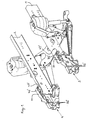
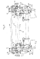
- the two of the truck are part of its chassis frame Frame side members labeled 1 and 2. At the front end of each of them is a multifunction bearing plate 3, 4 attached. These front multi-function end shields 3, 4 serve to accommodate a large number of vehicle parts, including those which are attributable to the front mounting of the cab 5.
- the front cab mounting includes the following components, namely two spring-damper legs 6, 7, a U-shaped stabilizer arm 8, two seen from above rear bearing blocks 9, 10, two spring-damper leg holders 11, 12 and two front Connection brackets 13, 14.
- the left-hand components of the cab mounting are related to the vehicle's longitudinal axis mirror-symmetrical to the right-hand side Components trained and arranged.
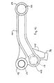
- the U-shaped stabilizer arm 8 consists of a right longitudinal arm 15, a left longitudinal arm 16, a cross rod connecting these at the front 17 and two, each above the transition area between crossbar 17th and a longitudinal arm 15, 16 arranged bearing eyes 18, 19.
- bearing eyes 18, 19 bearings 20, 21 are installed, their axes of rotation in a horizontal Transverse line 22 are aligned.
- each of the two is at the rear end Longitudinal arms 15, 16 of the stabilizer rocker 8 also have a bearing eye 23, 24 provided with built-in bearing 25, 26, the axes of rotation of which are also in one horizontal cross line 27 aligned with each other, which runs parallel to the cross line 22.
- the U-shaped stabilizer link 8 can either be a one-piece drop forge or cast steel part or alternatively from three prefabricated Individual parts. In the latter case, the two longitudinal arms 15, 16 including all bearing eyes and other parts either through a drop forged or steel casting and the crossbar 17 either through one Pipe or a full-material drop forged part can be formed. To These three parts will then be machined accordingly welded together.
- the longitudinal arms 15, 16 of the stabilizer rocker 8 are shaped and arranged that they are targeted in the longitudinal direction in a frontal crash of the truck are deformable and at the same time have an energy-absorbing effect.
- the longitudinal arms 15, 16 of the stabilizer arm 8 are between the front and rear end - viewed from the side - slightly bent upwards and - viewed from above - odd, for example S-shaped or Z-shaped, what defines deformable folding, bending or in a frontal crash Kink zones means.
- the two longitudinal arms 15, 16 are preferably inside the U-shaped stabilizer arm 8 is arranged swept towards one another in the sense that their rear ends 23, 24 are less spaced apart than theirs front ends 18, 19.
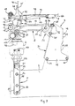
- the U-shaped stabilizer rocker arm 8 is on the rear of the longitudinal arms 15, 16th arranged bearing eyes 23, 24 and the bearings 25, 26 installed therein longitudinally guided across and pivotable about the axis of rotation - line 27 - on the two Bearing blocks 9, 10 articulated. Each of them is at the back of one of the two multi-function end shields 3, 4 releasably attached to its lower End region 28 by two screw connections 29, 30, one of which (29) entirely front and the other (30) is arranged at the very rear.
- each rear has Bearing block 9, 10 above this fastening zone 28, but below the connection level for the stabilizer arm 8 in the event of a frontal crash of the truck defines deformable fold or crease zone by constructive measures such as cross-sectional reductions, material weakening, indentations, constrictions or the like can be realized.
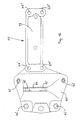
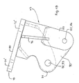
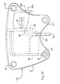
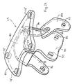
- each bearing block 9, 10 is composed of two parts, a defined deformable main part 31 and one flanged to the front thereof by means of screw connections 32 attached to the connector 33
- Longitudinal arm 15 or 16 of the stabilizer rocker 8 on the rear end Bearing eye and the bearing built into it are guided crossways and across one Bearing axis or screw 40 is longitudinally guided and pivoted.
- Both the main part 31 and the connecting part 33 of a bearing block 9, 10 are preferably realized by a bent sheet metal part.
- the connecting part 33 of each bearing block 9, 10 in Seen from above, bent in a U-shape and in detail has a flat rear Connection plate 34 with a plurality of screw feed-through holes 35 and on both sides arranged on the connecting plate 34 vertically forward and parallel to each other angled side walls 36, 37 with mutually aligned bores 38, 39 for passing through a bearing axis or bearing screw 40.
- the main part 31 of a pedestal 9, 10 has a bent sheet metal part a flat and slightly inclined front connection plate 41 with several Screw feed-through holes 42 for front flanging and fastening of the connecting part 33 by means of a corresponding number of screw connections 43 on.
- On the front connection plate 41 close on both sides angled backwards, parallel to each other 44, 45 on, in the lower region screw through holes 46, 47 for the two screw connections 29, 30 are formed.
- the associated screw through holes in the respective multifunction bearing shield are 46 'and 47' designated.
- the two side cheeks 44, 45 of the main part 31 of a bearing block 9, 10 by a distance ensuring their distance, not in the deformation zone arranged crossbar 48 connected to each other.
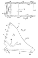
- 23 is the crossbar 48 by a rear end on a side cheek 44 or 45 angled towards the opposite side wall 45 or 44 and formed on this cross beam 49 welded on in a supporting manner. in the In contrast to the example according to FIGS.
- the cross beam 48 is in the front area of the main part 31 of each bearing block 9, 10, but spatially arranged behind the front screw connection 29 and for example by a Angle section piece 50 (as shown), a bolt or a piece of pipe realized, that extends between the two side cheeks 44, 45 welded to them is.
- the cross-member 50 serves as a stop, which in the event of a frontal crash of the truck with deformation of the rear bracket 9, 10 rotatory around the front screw connection 29 on the top 51 of the bearing block 9 or 10 accommodating multi-function end shield 3 or 4 limiting comes to the plant.
- the cab 5 is at the front with its base 66 on the two connection brackets 13, 14 attached, articulated with these on the two spring-damper legs 6, 7 and cushioned over this in relation to the chassis frame 1, 2.
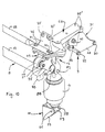
- the spring-damper legs 6, 7 on the chassis frame are the two spring-damper leg holders 11, 12 provided. Each of them is laterally the same in the outside Elevation on a multifunction bearing plate 3 or 4 can be detached using screw holes 56 'passing through screw connections 56 and takes between two sidewalls 57, 58 guided crosswise and pivoted at the bottom End of a spring-damper leg 6 or 7 arranged bearing eye 59 with built-in Camp 60 on.
- a bearing axis running continuously in the longitudinal direction of the vehicle 61 provides the connection between the bearing 60 and the spring-damper leg holder 11 or 12 and forms the pivot axis for the spring-damper leg articulated in this way 6 and 7.
- the upper end of each spring-damper leg 6, 7 is taken in a connection console 13 or 14.
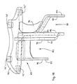
- Each of the two connection brackets 13, 14 is composed of two parts, namely an upper support member 62 on which the cab 5 is fixed, and one lower bearing part 63, on which a spring-damper leg 6 or 7 and another Place the stabilizer rocker 8 with one of the two bearing eyes arranged on it 18, 19 are hinged with built-in bearings 20, 21.
- each connection bracket 13, 14 is a large area Plate formed, with its rear section 73 via several vertical screw connections 64, 65 is attached to the cab floor 66 and with a front section 74 protrudes a certain amount from the front of the cab floor 66 and one forms oblique support ramp 67.
- each connector bracket support 62 is in the rear section 73 formed flat and pulled up obliquely upwards in the front section 74, on its front section 68, the crossbar 69 is supported and is attached.
- the thickness of the support plate increases from the back to about In the middle of its longitudinal extension wedge-shaped to a maximum and then from this thickest cross-sectional point back to a certain point up to the front end Dimension, whereby this last-mentioned area forms the support ramp 67.
- each connection bracket 13, 14 has at the transition between flat Plate area and sloping support ramp area protruding upwards Fastening flange 75 on which the cab floor 66 with a raised Front edge 76 connected to the stop and by means of several horizontal screw connections 77 is attached.
- the associated screw holes are 77 ' designated.
- the rear cab floor area 78 is on the flat top of the rear portion 73 of the connector bracket support 62 supported and clamped there by means of the vertical screw connections 64, 65, the front vertical screw connections 64 in the area of the largest Panel thickness and the vertical screw connections 65 at the rear panel end area are arranged.
- the associated screw holes are labeled 64 'and 65'.
- each connection bracket 13, 14 has an end plate 79 at the top flat top 80 with which it is on the flat bottom 70 of the support ramp 67 flanged a connection bracket support part 62 and there by means of the vertical screw connections 71, 72 is clamped.
- the associated screw holes in the Plates 67 and 79 are labeled 71 'and 72', respectively.
- connection bracket support part 62 The front vertical screw connections 71, with which the bearing part 63 of each connection bracket 13, 14 with its end plate 79 on the support ramp 67 of a connection bracket support part 62 is clamped, are preferably also for attachment the crossbar 69 pulled up on the upper part 74 of the supporting part.
- each connection bracket 13, 14 has, in addition to the end plate 79 first outer mouth 81 spaced downward therefrom and a second, further up, but also from the end plate 79 downwardly spaced interior Mouth 82 on.
- the outer mouth 81 is to the side of walls 83, 84 with these penetrating, horizontally transversely aligned bores 85, 86 limited and is used for the side Recording and storage of the from a bearing eye 87 with built-in Bearing 88 existing upper end of a spring-damper leg 6 or 7 by means of a transverse bearing axis 89 on the bearing part 63 of a connection bracket 13, 14.
- connection bracket bearing part 63 also laterally through walls 90, 91 with these penetrating, horizontally across aligned holes 92, 93 limited and is used for lateral guidance and storage of a bearing eye arranged at the front on the stabilizer arm 8 18 and 19 together with bearings 20 and 21 installed therein by means of a transverse one Bearing axis 94 or 95 on the bearing part 63 of a connection bracket 13, 14th
- the inner boundary wall 84 is the first outer Mouth 81 and the outer boundary wall 90 of the second inner mouth 82 formed by a single common partition. All mouth-limiting Walls 83, 84, 90, 91 are supported on the underside of the upper end plate 79 connected.
- each connection bracket 13, 14 can either by a Steel casting or by a welded structure made of several welded together Steel sheets can be realized.
- the outer boundary wall 83 of the outer mouth 81 bent towards the inner boundary wall 84, welded there and also through a vertical rib 96 to the end plate 79 supported.
- each connection bracket 13, 14 is preferably by a Ductile iron part realized.
- the front vertical screw connections 71 with which the bearing part 63 of each connection bracket 13, 14 with its upper end plate 79 on the support ramp 67 one Connection bracket support member 62 is clamped, are preferably on such Limit load designed that if in the event of a frontal crash of the truck different deformation zones in the cab bearing elements 9, 10, 15, 16 to are deformed to their predetermined limits, said front vertical screw connections 71 tear off, the adjacent rear vertical screw connections 72 but only be stretched and each connection bracket bearing part 63 then rotates can move around these rear vertical screw connections 72, whereby an axial offset of the spring damper leg spaced downward from the end plate 63 and stabilizer rocker articulation points 81, 82 to the rear.
- the front cab mounting also has a compression of the cab device limiting when tipping.
- This consists of two of equal length Stop feet 97, 98, each of which protrudes below at the front end, respectively a longitudinal arm 15, 16 of the U-shaped stabilizer arm 8 is arranged, and two associated stops 99, 100 arranged fixed to the frame.
- the stop 99 or 100 by an interchangeable Stop plate formed on a raised, by a Cross bar formed upper end of a spring-damper leg holder 11 and 12 respectively is optionally attached elastically resilient or cushioned, the stop plate load-bearing bracket cross bar and the raised bracket wall by a stiffening ribs 101 and 102 welded to them are supported.
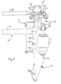
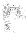
- FIG. 3 shows the cab in the untilted position and the stop feet 97, 98 in such a distance from the associated stops 99 and 100 that the normal deflection of the cab 5 is not hindered while driving.
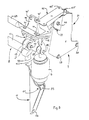
- Fig. 4 shows the cab 5 in the maximum tilted position, in which the stop feet Sit 97 or 98 on the stops 99 or 100 and so on Compression of the spring-damper legs 6, 7 hinder.
- this cab tipping process describe the stop feet 97, 98 a rotational movement about the axis of rotation 27, which is caused by the rear-end bearing screw connections 40 the U-shaped stabilizer rocker 8 with the bearing blocks 9, 10 goes.
- the stop 99, 100 is not on the spring-damper leg holder 11 or 12, but on its own holder 103 or 104 arranged, which in turn on one of the two multi-function end shields 3 or 4 is attached and otherwise other, not of interest here Serves purposes.
- the location, design and type of attachment of the stop plates are same as in the aforementioned case.
- the stop feet 97, 98 are preferably each in one piece with the longitudinal arms 15, 16 of the U-shaped stabilizer rocker 8 and rear - like 12 - through a strut 105 to the respective longitudinal arm 15 or 16 stiffened.
- the respective stop foot 97 or 98 goes down on one longitudinal-arm-front receiving eye 106, 107 from, in the inside blind bore the associated end of the cross bar 17 form and optionally also inserted non-positively and then welded.
- Comfort is achieved through long spring travel. Because the rear bearing of the stabilizer arm arranged on the frame side in a quiet "area of the chassis frame there is also an improvement in cross shaking. The separation of the Comfort bearings from the pivot bearing for tipping ensure optimal design.
- the cost reduction is achieved in that compared to previous cab bearings different parts are omitted.
- the freedom from tension is achieved in that compensation options between Stabilizer arm and chassis frame on the one hand and driver's cab on the other given are.
- crash optimization takes place through energy-consuming design and / or Arrangement of different storage parts. Here are a few comments.
- the rear bearing blocks 9, 10 experience a certain level of stress locally strong deformations in the intended places, whereby a shift of the rear stabilizer arm bearings to the rear and done below. Depending on the size of those acting on the cab from the front Force can then even roll over the stabilizer rocker 8 to the rear. Because of this effect brought about by targeted component design, in the event of a crash, the largest possible displacement of the driver's cab towards the rear achieve the chassis as a combination of the bow movement of the stabilizer swing bearing points around a deep axis of rotation and double Stabilizer arm length from the stabilizer arm rollover movement. A firm connection remains during this entire movement preserved between the cab and the chassis.
- the rear bearing blocks 9, 10 build relatively high, the height of which, for. B. double the length in the lower area Connection zone 28 is. This favors because of that in the area of the upper end each bearing block 9, 10 lying connection point 40 of the stabilizer rocker 8 the deformation of the bearing blocks 9, 10 in the areas specified in the design.
Landscapes
- Engineering & Computer Science (AREA)
- Chemical & Material Sciences (AREA)
- Combustion & Propulsion (AREA)
- Transportation (AREA)
- Mechanical Engineering (AREA)
- Body Structure For Vehicles (AREA)
- Vehicle Body Suspensions (AREA)
Claims (30)
- Suspension avant de la cabine basculante d'un camion sur son châssis et, à ce niveau, sur deux flasques multifonctions (3, 4) fixés chacun à l'extrémité antérieure d'un longeron de cadre (1, 2), comprenant les éléments suivants :lesdits composants étant disposés et reliés entre eux ainsi qu'avec la cabine (5) comme suit :a) deux combinés ressort/amortisseur (6, 7),b) un stabilisateur (8) en forme de U - vu de dessus - constitué de bras longitudinaux droit et gauche (15, 16), d'une barre transversale (17) solidarisant à l'avant ces bras entre eux et deux coussinets (18, 19) disposés à chaque fois au-dessus de la zone de transition entre la traverse (17) et un bras longitudinal (15, 16),c) deux supports d'articulation postérieurs (9, 10),d) deux supports de combiné ressort/amortisseur (11, 12) ete) deux consoles antérieures (13, 14) constituées chacune d'un élément supérieur porteur (62) et d'un élément inférieur d'articulation (63),f) l'élément inférieur d'articulation de chaque console est bridé sur le dessous à celle de l'élément supérieur porteur (62) de manière amovible,g) à chacun des flasques multifonctions (3, 4), sont fixés de manière amovible, à l'avant, sur la face extérieure latérale, un support de combiné ressort/amortisseur (11, 12) et, à l'arrière, en haut, un support d'articulation postérieur (9, 10),h) chacun des deux combinés ressort/amortisseur (6, 7) est articulé sur pivot, en bas, sur un support de combiné ressort/amortisseur (11, 12) et, en haut, sur l'élément d'articulation (63) d'une console (13, 14),i) le stabilisateur (8) est guidé transversalement et longitudinalement ainsi qu'articulé sur pivot, à l'arrière, sur les deux supports d'articulation postérieurs (9, 10), par l'intermédiaire de coussinets (23, 24) à paliers intégrés (25, 26) disposés à ce niveau à l'extrémité de ses bras longitudinaux (15, 16), et d'un axe ou d'une vis de palier (40),j) la cabine (5) est fixée par son plancher (66) aux deux consoles (13, 14), reposant en haut sur leur élément porteur (62) et suspendue par rapport au cadre du châssis (1, 2 ou 3, 4) par l'intermédiaire des consoles (13, 14) ainsi que des combinés ressort/amortisseur (6, 7), etk) la cabine (5) est guidée transversalement par l'intermédiaire des consoles (13, 14), par leurs éléments d'articulation (63), et articulée de manière à pouvoir basculer à l'extrémité antérieure du stabilisateur (8), par l'intermédiaire de paliers (20, 21) montés dans les coussinets (18, 19), à l'aide d'axes d'articulation (94, 95) alignés suivant une ligne horizontale (22) et emprisonnés dans les éléments d'articulation (63) des consoles (13, 14).
- Suspension avant de cabine suivant la revendication 1, caractérisée en ce que l'élément supérieur porteur (62) de chaque console (13, 14) est constitué d'une plaque de grande surface dont la partie postérieure (73) est fixée au plancher de la cabine (66) par l'intermédiaire de plusieurs boulons verticaux (64, 65) et dont la partie antérieure (74) dépasse d'une certaine cote le plancher de la cabine (66) et forme une rampe d'appui inclinée (67), sur la face supérieure libre (68) de laquelle peuvent être fixés au moyen de plusieurs boulons antérieurs et postérieurs (71, 72) une barre transversale (69) stabilisant la position des deux consoles (13, 14) et, à la face inférieure montant en biais vers l'avant (70), un élément d'articulation (63).
- Suspension avant de cabine suivant la revendication 2, caractérisée en ce que la face supérieure de chaque élément porteur (62) des consoles est horizontalement plane à sa partie arrière (73) et relevée en biais vers le haut à sa partie avant (74), la barre transversale (17) reposant et étant fixée sur la partie la plus antérieure (68), et en ce que l'épaisseur de l'élément porteur (62) augmente progressivement de l'arrière jusqu'au milieu environ de son extension longitudinale, où elle atteint son maximum, et qu'elle diminue alors à nouveau jusqu'à une certaine cote de ce point de section la plus épaisse jusqu'à l'extrémité antérieure, cette dernière plage citée constituant la rampe d'appui (67).
- Suspension avant de cabine suivant l'une des revendications précédentes, caractérisée en ce que l'élément porteur (62) de chaque console (13, 14) présente au niveau de la transition entre zone plane (73) de la plaque et zone inclinée de la rampe d'appui (74) une bride de fixation (75) en saillie vers le haut, à laquelle le plancher de la cabine (66) est raccordé en butée par un bord antérieur relevé (76) et fixé au moyen de plusieurs boulons horizontaux (77), tandis que la partie adjacente du plancher de la cabine, vers l'arrière (78), repose sur la face supérieure plane de la partie postérieure (73) de l'élément porteur (62) de la console et y est fixée au moyen de plusieurs boulons verticaux (64) disposés dans la zone de la plus grande épaisseur et de boulons verticaux (65) disposés au niveau de la zone terminale postérieure.
- Suspension avant de cabine suivant l'une des revendications 2 et 3, caractérisée en ce que l'élément d'articulation (63) de chaque console (13, 14) présente en haut une plaque frontale (79) à face supérieure plane (80) par laquelle il est bridé sur la face inférieure plane (70) de la rampe d'appui (67) de l'élément porteur (62) d'une console et où il est fixé au moyen des boulons verticaux (71, 72).
- Suspension avant de cabine suivant la revendication 5, caractérisée en ce que les boulons verticaux antérieurs (71) par lesquels l'élément d'articulation (63) de chaque console (13, 14) est fixé par sa plaque frontale supérieure (79) à la rampe d'appui (67) de l'élément porteur (62) d'une console servent en même temps à la fixation de la barre transversale (69) à l'avant de la partie (68) de la face supérieure de l'élément porteur.
- Suspension avant de cabine suivant l'une des revendications 5 et 6, caractérisée en ce que les boulons verticaux antérieurs (71) par lesquels l'élément d'articulation (63) de chaque console (13, 14) est fixé par sa plaque frontale supérieure (79) à la rampe d'appui (67) de l'élément porteur (62) d'une console sont conçus pour supporter une sollicitation limite telle qu'en cas de collision frontale, différentes zones de déformation prévues dans les organes de suspension de la cabine (8, 9, 10) sont déformées jusqu'aux limites qui leur ont été imposées, mais qu'il subsiste une force horizontale dirigée vers l'arrière, que lesdits boulons verticaux antérieurs (71) sont arrachés, mais que les boulons verticaux postérieurs adjacents (72) ne sont qu'étirés et que l'élément d'articulation (63) de chaque console peut alors se déplacer dans un mouvement de rotation autour de ces boulons verticaux postérieurs (72), ce qui se traduit par un déport axial vers l'arrière des points d'articulation du combiné ressort/amortisseur et du stabilisateur, maintenus écartés vers le bas par la plaque frontale (79).
- Suspension avant de cabine suivant l'une des revendications précédentes, caractérisée en ce que l'élément d'articulation (63) de chaque console (13, 14) présente, outre une plaque frontale supérieure (79) par laquelle il est bridé à la rampe d'appui (67) de l'élément porteur (62) de la console, une première mâchoire extérieure (81) maintenue vers le bas à distance de la plaque frontale (79) et dotée de parois de délimitation latérales (83, 84) et de lumières (85, 86) traversant ces dernières et destinées à recevoir et à supporter avec guidage latéral l'extrémité supérieure (87, 88) d'un combiné ressort/amortisseur (6, 7) au moyen d'un axe d'articulation traversant (89), ainsi qu'une seconde mâchoire intérieure (2) disposée plus haut mais aussi maintenue vers le bas à distance de la plaque frontale (79) et dotée de parois de délimitation latérales (90, 91) et de lumières (92, 93) traversant ces dernières et destinées à recevoir et à supporter avec guidage latéral un coussinet (18, 19) disposé avec son palier (20, 21) à l'extrémité antérieure du stabilisateur (8) au moyen d'un axe d'articulation traversant (94, 95).
- Suspension avant de cabine suivant la revendication 8, caractérisée en ce que la paroi de délimitation intérieure (84) de la mâchoire extérieure (81) et la paroi de délimitation extérieure (90) de la mâchoire intérieure (82) de l'élément d'articulation (63) de chaque console sont constituées d'une seule cloison commune et que toutes les parois limitant les mâchoires sont raccordées en appui à la face inférieure de la plaque frontale supérieure (79).
- Suspension avant de cabine suivant l'une des revendications précédentes, caractérisée en ce que l'élément d'articulation (63) de chaque console (13, 14) est réalisé soit sous forme d'une pièce moulée en acier, soit formé d'un assemblage soudé de plusieurs pièces préformées en tôle d'acier.
- Suspension avant de cabine suivant la revendication 1, caractérisée en ce que le stabilisateur en forme de U (8) est soit réalisé sous forme d'une pièce matricée monobloc, soit composé de trois éléments préfabriqués, les deux bras longitudinaux (15, 16), y compris tous les coussinets et autres pièces, étant dans ce dernier cas constitués d'une pièce monobloc matricée ou moulée en acier, et la barre transversale (17) soit d'un tube soit également d'une pièce matricée pleine, et ces trois éléments étant assemblés par soudage.
- Suspension avant de cabine suivant l'une des revendications 1 et 11, caractérisée en ce que les bras longitudinaux (15, 16) du stabilisateur en forme de U (8) ont une forme telle qu'en cas de collision frontale, ils puissent se déformer dans des conditions bien définies dans la direction horizontale et aient ainsi un effet d'absorption de l'énergie.
- Suspension avant de cabine suivant la revendication 12, caractérisée en ce que les bras longitudinaux (15, 16) du stabilisateur en forme de U (8) sont légèrement recourbés vers le haut entre extrémités antérieure et postérieure - vu de côté - et sont de forme non droite - vu de dessus -, par exemple en S ou en Z, et présentent ainsi en cas de collision frontale des zones de pliage, flexion ou flambage à possibilités de déformation bien définies.
- Suspension avant de cabine suivant l'une des revendications 11 à 13, caractérisée en ce que les deux bras longitudinaux (15, 16) du stabilisateur en forme de U (8) sont disposés en flèche, en ce sens que leurs extrémités postérieures sont moins espacées l'une de l'autre que leurs extrémités antérieures.
- Suspension avant de cabine suivant la revendication 1, caractérisée en ce que chaque support (9, 10) prévu pour le montage du stabilisateur (8) est fixé au flasque multifonction (3, 4) solidaire du châssis, au niveau de sa zone terminale inférieure (28), par deux boulons (29, 30), disposés l'un (29) tout à l'avant et l'autre (30) tout à l'arrière, et présente par ailleurs, au-dessus de cette zone de fixation, mais au-dessous du plan de raccordement du stabilisateur (8), une zone de pliage ou de flambage à possibilités de déformation bien définies en cas de collision frontale, obtenues par mesures prises au niveau du dessin, telles que réductions de section, dépouilles, embrèvements, étranglements, etc.
- Suspension avant de cabine suivant la revendication 15, caractérisée en ce que chaque support d'articulation (9, 10) prévu pour le montage du stabilisateur (8) se compose de deux éléments, un élément principal (31) à possibilités de déformation bien définies et, bridé à l'avant de ce dernier, un élément de raccordement (33) fixé au moyen de boulons (32), sur lequel s'articule sur pivot un bras longitudinal (15, 16) du stabilisateur (8), avec guidage transversal par l'intermédiaire d'un coussinet (23, 24) disposé à son extrémité postérieure et du palier associé (25, 26), et avec guidage longitudinal par l'intermédiaire d'un axe ou d'une vis d'articulation traversante (40).
- Suspension avant de cabine suivant la revendication 16, caractérisée en ce que l'élément principal (31) comme l'élément de raccordement (33) de chaque support d'articulation (9, 10) prévu pour le montage du stabilisateur (8) sont réalisés sous forme de pièces en tôle pliée.
- Suspension avant de cabine suivant la revendication 17, caractérisée en ce que l'élément de raccordement (33) de chaque support d'articulation (9, 10) prévu pour le montage du stabilisateur (8) est, vu de dessus, recourbé en forme de U et présente à l'arrière une plaque de raccordement plane (34) comportant plusieurs trous de passage de vis (35) ainsi que, des deux côtés de la plaque de raccordement (34), des joues latérales (36, 37) verticales et parallèles, dirigées vers l'avant et traversées de trous alignés (38, 39) pour le passage d'un axe ou d'une vis d'articulation (40).
- Suspension avant de cabine suivant la revendication 17, caractérisée en ce que l'élément principal (31) de chaque support d'articulation (9, 10) prévu pour le montage du stabilisateur (8) présente une plaque de raccordement antérieure plane et légèrement inclinée vers l'arrière (41), comportant plusieurs trous de passage de vis (42) pour le bridage et la fixation à l'avant de l'élément de raccordement (33) au moyen d'un nombre correspondant de boulons (43), et que des deux côtés de la plaque de raccordement (41), sont prévues des joues latérales (44, 45) verticales et parallèles, dirigées vers l'arrière et traversées de trous de passage de vis (46, 47) pour la fixation au flasque multifonction (3, 4) au moyen des boulons (29, 30).
- Suspension avant de cabine suivant la revendication 19, caractérisée en ce que les deux joues latérales (44, 45) de l'élément principal (31) de chaque support d'articulation (9, 10) prévu pour le montage du stabilisateur (8) sont reliées par une traverse (48) assurant leur écartement, non disposée dans la zone de déformation.
- Suspension avant de cabine suivant la revendication 20, caractérisée en ce que la traverse (48) est constituée d'une joue transversale (49) coudée à l'extrémité postérieure d'une joue latérale (44 ou 45) en direction de la joue latérale opposée et soudée en appui sur cette dernière.
- Suspension avant de cabine suivant la revendication 19, caractérisée en ce que la zone de déformation située au niveau de chaque support d'articulation (9, 10) prévu pour le montage du stabilisateur (8) est réalisée sous forme d'un embrèvement ou d'une découpe (54, 55) sur ou dans l'arrière des joues latérales (44, 45), ce qui - vu dans la direction longitudinale - se traduit par une réduction de la section des joues latérales (44, 45) au-dessus de leurs zones de raccordement (28) situées à leur extrémité inférieure.
- Suspension avant de cabine suivant la revendication 20, caractérisée en ce que la traverse (48) est disposée dans la partie antérieure de l'élément principal (31) de chaque support d'articulation (9, 10) prévu pour le montage du stabilisateur (8), mais, dans l'espace, derrière le boulon antérieur (29), qu'elle est réalisée, par exemple, sous forme d'un morceau de cornière (50), d'un axe ou d'un morceau de tube et qu'elle est prévue comme butée qui, en cas de collision frontale et de déformation du support d'articulation (9, 10), vient porter, par rotation autour du boulon antérieur (29), sur la face supérieure (51) du flasque multifonction (3, 4) recevant le support d'articulation (9, 10), en limitant le déplacement.
- Suspension avant de cabine suivant l'une des revendications 15 à 23, caractérisée en ce que l'écartement entre les trous de passage de vis antérieurs (46) et la périphérie du support d'articulation (9, 10) est dimensionné de telle manière et/ou le boulon anténeur associé (29) par lequel un support d'articulation (9, 10) prévu pour le montage du stabilisateur (8) est fixé au flasque multifonction (3, 4) est conçu pour supporter une sollicitation limite telle que, lorsqu'en cas de collision frontale, le support d'articulation (9, 10) venu porter durant la déformation par sa traverse formant butée (48, 50) sur la face supérieure (51) du flasque multifonction et déformé au maximum continue d'être soumis à une force horizontale dirigée vers l'arrière, la liaison antérieure se désintègre, le support d'articulation (9, 10) se déchirant alors vers la périphérie et/ou le boulon antérieur (29) étant arraché, le support d'articulation (9, 10) pouvant alors basculer vers l'arrière par rotation autour du boulon postérieur (30), et - suivant l'intensité de la force agissant de l'avant - un basculement du stabilisateur (8) pouvant également avoir lieu, avec déport axial correspondant de la cabine (5) vers l'arrière du double de la longueur des bras du stabilisateur.
- Suspension avant de cabine suivant la revendication 1, caractérisée en ce qu'il est prévu un dispositif limitant le débattement de la cabine (5) lors d'une opération de basculement, de telle manière que le stabilisateur (8) présente deux pieds de butée (97, 98), dont chacun est disposé en saillie vers le bas, à l'extrémité antérieure d'un bras longitudinal (15, 16), et à chacun desquels est associé une butée (99, 100) solidaire du cadre.
- Suspension avant de cabine suivant la revendication 25, caractérisée en ce que les butées (99, 100) du dispositif de limitation du débattement se trouvent systématiquement à une distance suffisante du bord inférieur des pieds de butée (97, 98) pour ne pas entraver le débattement de la cabine non basculée dans les limites imposées durant la marche.
- Suspension avant de cabine suivant la revendication 25, caractérisée en ce que chaque butée (99, 100) constituant une partie du dispositif de limitation du débattement est constituée d'une plaque de butée interchangeable, fixée, le cas échéant en flexion élastique ou avec suspension, à un support de combiné ressort/amortisseur (11, 12) solidaire du châssis et de préférence à un flasque multifonction (3, 4) et, à ce niveau, à une extrémité supérieure relevée constituée par une nervure transversale.
- Suspension avant de cabine suivant la revendication 25, caractérisée en ce que chaque butée (99, 100) constituant une partie du dispositif de limitation du débattement est constituée d'une plaqùe de butée interchangeable, fixée, le cas échéant en flexion élastique ou avec suspension, à une nervure transversale d'un support (103, 104), lui-même solidaire du châssis et fixé de préférence à un flasque multifonction (3, 4).
- Suspension avant de cabine suivant la revendication 25, caractérisée en ce que chacun des deux pieds de butée (97, 98) est en saillie en bas d'un oeil récepteur (106, 107) ménagé à l'extrémité antérieure d'un bras longitudinal (15, 16), dans le trou borgne intérieur duquel est insérée et fixée l'extrémité associée de la barre transversale (17) du stabilisateur (8).
- Suspension avant de cabine suivant la revendication 25, caractérisée en ce que chacun des deux pieds de butée (97, 98) est raidi à l'arrière par une jambe de force (105) en direction du bras longitudinal considéré (15, 16) et constitue une seule pièce avec les bras longitudinaux (15, 16) du stabilisateur en forme de U (8).
Applications Claiming Priority (2)
| Application Number | Priority Date | Filing Date | Title |
|---|---|---|---|
| DE19831367 | 1998-07-13 | ||
| DE19831367A DE19831367A1 (de) | 1998-07-13 | 1998-07-13 | Vordere Lagerung des kippbaren Fahrerhauses eines Lastkraftwagens |
Publications (3)
| Publication Number | Publication Date |
|---|---|
| EP0972696A2 EP0972696A2 (fr) | 2000-01-19 |
| EP0972696A3 EP0972696A3 (fr) | 2002-11-20 |
| EP0972696B1 true EP0972696B1 (fr) | 2004-08-04 |
Family
ID=7873901
Family Applications (1)
| Application Number | Title | Priority Date | Filing Date |
|---|---|---|---|
| EP99111004A Expired - Lifetime EP0972696B1 (fr) | 1998-07-13 | 1999-06-10 | Palier avant pour la cabine basculante d'un camion |
Country Status (2)
| Country | Link |
|---|---|
| EP (1) | EP0972696B1 (fr) |
| DE (2) | DE19831367A1 (fr) |
Families Citing this family (2)
| Publication number | Priority date | Publication date | Assignee | Title |
|---|---|---|---|---|
| WO2009057013A2 (fr) * | 2007-10-31 | 2009-05-07 | Ford Otomotiv Sanayi Anonim Sirketi | Bloc arrêtoir |
| CN111845966B (zh) * | 2020-06-22 | 2022-06-28 | 东风柳州汽车有限公司 | 一种升降式驾驶室悬置机构 |
Family Cites Families (9)
| Publication number | Priority date | Publication date | Assignee | Title |
|---|---|---|---|---|
| DE3730338A1 (de) * | 1987-09-10 | 1989-03-23 | Daimler Benz Ag | Stabilisator fuer kraftfahrzeuge |
| SE468315B (sv) * | 1991-05-03 | 1992-12-14 | Volvo Ab | Anslagsstopp foer saavael oevre som nedre aendlaege hos en fordonshytt |
| AT403365B (de) * | 1993-04-19 | 1998-01-26 | Steyr Nutzfahrzeuge | Vordere lageranordnung für das fahrerhaus eines lastkraftwagens |
| DE4413414A1 (de) * | 1994-04-18 | 1995-10-19 | Daimler Benz Ag | Anordnung zur Befestigung von Schwenklagern für Fahrerhäuser von Lastkraftwagen |
| SE9503271L (sv) * | 1995-09-21 | 1997-03-22 | Scania Cv Ab | Chassidel |
| DE19537722A1 (de) * | 1995-10-10 | 1997-04-17 | Man Nutzfahrzeuge Ag | Vordere Lagerung für das kippbare Fahrerhaus eines Frontlenker-Lastkraftwagen |
| DE19612502A1 (de) * | 1996-03-29 | 1997-10-02 | Man Nutzfahrzeuge Ag | Vordere Lagerung des kippbaren Fahrerhauses eines Lastkraftwagen |
| JPH10316013A (ja) * | 1997-05-21 | 1998-12-02 | Hino Motors Ltd | トラックのシャシフレーム構造 |
| GB9719577D0 (en) * | 1997-09-16 | 1997-11-19 | Hendrickson Europ Limited | Suspension systems |
-
1998
- 1998-07-13 DE DE19831367A patent/DE19831367A1/de not_active Withdrawn
-
1999
- 1999-06-10 DE DE59910111T patent/DE59910111D1/de not_active Expired - Lifetime
- 1999-06-10 EP EP99111004A patent/EP0972696B1/fr not_active Expired - Lifetime
Also Published As
| Publication number | Publication date |
|---|---|
| DE19831367A1 (de) | 2000-01-20 |
| EP0972696A2 (fr) | 2000-01-19 |
| EP0972696A3 (fr) | 2002-11-20 |
| DE59910111D1 (de) | 2004-09-09 |
Similar Documents
| Publication | Publication Date | Title |
|---|---|---|
| EP0972700B1 (fr) | Palier avant pour la cabine basculante d'un camion | |
| EP0940272B1 (fr) | Chassis pour un camion à cabine avancée | |
| DE19536460B4 (de) | Teilrahmen für ein Fahrzeug | |
| DE69825711T2 (de) | Fahrerhaus für eine Baumaschine | |
| DE602004000516T2 (de) | Vorbaustruktur für ein Kraftfahrzeug | |
| EP0798198B1 (fr) | Palier avant pour la cabine basculante d'un camion | |
| DE112012004693T5 (de) | Kraftfahrzeug-Heckkarosseriestruktur | |
| EP0968904B1 (fr) | Structure de plancher d'une carrosserie auto-porteuse d'un véhicule | |
| DE4200482A1 (de) | Aufhaengungstragestruktur fuer ein selbstfahrendes fahrzeug | |
| DE602004013204T2 (de) | Anordnung für fahrzeugkabinen | |
| DE19812679B4 (de) | Versteifungsanordnung für eine Unterbaugruppe eines Kraftfahrzeugs | |
| EP0972698B1 (fr) | Palier avant pour la cabine basculante d'un camion | |
| EP1306290B1 (fr) | Structure avant de véhicule | |
| EP0972699B1 (fr) | Palier avant pour la cabine basculante d'un camion | |
| DE102004041165A1 (de) | Fahrzeugkarosseriestruktur | |
| DE19961670C2 (de) | Hintere Lagerung des kippbaren Fahrerhauses eines Frontlenker-Lastkraftwagens | |
| DE60113932T2 (de) | Stossenergieabsorbierende Struktur für ein Kraftfahrzeug | |
| EP0940319A2 (fr) | Chassis d'un véhicule utilitaire lourd | |
| EP3608213B1 (fr) | Machine de travail agricole | |
| EP0972697B1 (fr) | Palier avant pour la cabine basculante d'un camion | |
| DE102005014401B4 (de) | Lagerung eines kippbaren Fahrerhauses | |
| EP0972696A2 (fr) | Palier avant pour la cabine basculante d'un camion | |
| EP0940322B1 (fr) | Chassis pour véhicule utilitaire lourd | |
| EP0621170A1 (fr) | Aménagement d'un support avant pour une cabine de conducteur d'un camion | |
| EP0940324A1 (fr) | Chassis pour véhicule utilitaire lourd |
Legal Events
| Date | Code | Title | Description |
|---|---|---|---|
| PUAI | Public reference made under article 153(3) epc to a published international application that has entered the european phase |
Free format text: ORIGINAL CODE: 0009012 |
|
| AK | Designated contracting states |
Kind code of ref document: A2 Designated state(s): AT BE CH CY DE DK ES FI FR GB GR IE IT LI LU MC NL PT SE |
|
| AX | Request for extension of the european patent |
Free format text: AL;LT;LV;MK;RO;SI |
|
| PUAL | Search report despatched |
Free format text: ORIGINAL CODE: 0009013 |
|
| AK | Designated contracting states |
Kind code of ref document: A3 Designated state(s): AT BE CH CY DE DK ES FI FR GB GR IE IT LI LU MC NL PT SE |
|
| AX | Request for extension of the european patent |
Free format text: AL;LT;LV;MK;RO;SI |
|
| 17P | Request for examination filed |
Effective date: 20021030 |
|
| GRAH | Despatch of communication of intention to grant a patent |
Free format text: ORIGINAL CODE: EPIDOS IGRA |
|
| GRAH | Despatch of communication of intention to grant a patent |
Free format text: ORIGINAL CODE: EPIDOS IGRA |
|
| AKX | Designation fees paid |
Designated state(s): DE FR IT NL SE |
|
| 17Q | First examination report despatched |
Effective date: 20040224 |
|
| GRAA | (expected) grant |
Free format text: ORIGINAL CODE: 0009210 |
|
| AK | Designated contracting states |
Kind code of ref document: B1 Designated state(s): DE FR IT NL SE |
|
| REG | Reference to a national code |
Ref country code: IE Ref legal event code: FG4D Free format text: GERMAN |
|
| REF | Corresponds to: |
Ref document number: 59910111 Country of ref document: DE Date of ref document: 20040909 Kind code of ref document: P |
|
| REG | Reference to a national code |
Ref country code: SE Ref legal event code: TRGR |
|
| REG | Reference to a national code |
Ref country code: IE Ref legal event code: FD4D |
|
| PLBE | No opposition filed within time limit |
Free format text: ORIGINAL CODE: 0009261 |
|
| STAA | Information on the status of an ep patent application or granted ep patent |
Free format text: STATUS: NO OPPOSITION FILED WITHIN TIME LIMIT |
|
| ET | Fr: translation filed | ||
| 26N | No opposition filed |
Effective date: 20050506 |
|
| REG | Reference to a national code |
Ref country code: NL Ref legal event code: TD Effective date: 20110420 |
|
| REG | Reference to a national code |
Ref country code: FR Ref legal event code: CD |
|
| REG | Reference to a national code |
Ref country code: DE Ref legal event code: R081 Ref document number: 59910111 Country of ref document: DE Owner name: MAN TRUCK BUS AG, DE Free format text: FORMER OWNER: MAN NUTZFAHRZEUGE AG, 80995 MUENCHEN, DE Effective date: 20110518 Ref country code: DE Ref legal event code: R081 Ref document number: 59910111 Country of ref document: DE Owner name: MAN TRUCK & BUS AG, DE Free format text: FORMER OWNER: MAN NUTZFAHRZEUGE AG, 80995 MUENCHEN, DE Effective date: 20110518 |
|
| REG | Reference to a national code |
Ref country code: FR Ref legal event code: PLFP Year of fee payment: 18 |
|
| REG | Reference to a national code |
Ref country code: FR Ref legal event code: PLFP Year of fee payment: 19 |
|
| REG | Reference to a national code |
Ref country code: FR Ref legal event code: PLFP Year of fee payment: 20 |
|
| PGFP | Annual fee paid to national office [announced via postgrant information from national office to epo] |
Ref country code: NL Payment date: 20180625 Year of fee payment: 20 |
|
| PGFP | Annual fee paid to national office [announced via postgrant information from national office to epo] |
Ref country code: FR Payment date: 20180629 Year of fee payment: 20 |
|
| PGFP | Annual fee paid to national office [announced via postgrant information from national office to epo] |
Ref country code: SE Payment date: 20180627 Year of fee payment: 20 |
|
| PGFP | Annual fee paid to national office [announced via postgrant information from national office to epo] |
Ref country code: IT Payment date: 20180622 Year of fee payment: 20 Ref country code: DE Payment date: 20180831 Year of fee payment: 20 |
|
| REG | Reference to a national code |
Ref country code: DE Ref legal event code: R071 Ref document number: 59910111 Country of ref document: DE |
|
| REG | Reference to a national code |
Ref country code: NL Ref legal event code: MK Effective date: 20190609 |
|
| REG | Reference to a national code |
Ref country code: SE Ref legal event code: EUG |